Data Compression and Encoding Using Color

Data Compression and Encoding Using Color project is about developing coding for bar codes using color sensor technology. As security for products like books, dresses…Etc are increasing, Enhancements in development of coding system for bar codes are also increasing. Color sensor technology is a new technology which will increase bar codes compactness, security, and efficiency. This technology is based on color combinations of RGB which is explained in this document. Data-Compression-and-Encoding-Using-Color-project
Introduction:

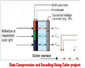
Color is formed when there is collision between light, object and observer. And the other form of light source is reflection, when light falls on the reflected object based on observing density of object color will form. For example consider a Red paper has the capacity to observe green and blue part of light this will reflect red part making it appear red to the observer. Colors are the mixer of three basic colors like Red, Green and Blue in fixed ratio. These colors are stored in the form of three numbers which are called digital color format. In Short these colors are called as RGB, there are different types of color formats like JPEG, BMP,BITMAP..ETC. 

Data Compression and Encoding Using Color document explains about

  1. Color sensor circuit and operation.
  2. Color sensing.
  3. Compactness, security, and efficiency.
  4. Color fading.
  5. Bar code Reader.
  6. Color code versus Bar code.
Download CSE Data Compression and Encoding Using Color project.

Adaptive Reliable Multipath Provisioning In Survivable WDM Mesh Networks

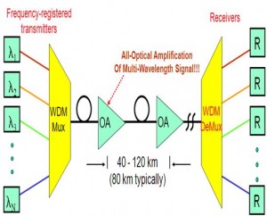
Wavelength Division multiplexing shortened to WDM means placing large number of optical carrier signals which possess a unique wavelength on a single fiber cable. The project “Adaptive Reliable Multipath Provisioning In Survivable WDM Mesh Networks” implements this WDM principle and provides an adaptive and flexible multipath provisioning.

adaptive-reliable-multipath-provisioning-in-survivable-wdm-mesh-networksThere are lots of advantages as to why WDM is used. Firstly it offers a high bandwidth which allows a wide range of signals to pass. Errors are minimal as there is an extremely low error rate. Also, another advantage is its low rate of signal attenuation. It is also a very secure way in mesh networks.

Project Description:

The project “Adaptive reliable multipath provisioning in survivable WDM mesh networks” requires two basic parameters for its connection in a typical fashion. The first parameter is a protection mechanism for network failures. And secondly, resourceful utilization of bandwidth of the system. It should also be capable of surviving in the existing network.

To meet these requirements, the VCAT (virtual concatenation) is used to break the bandwidth into individual payload at source end while providing concatenated payload at destination mode. The LCAS (Link Capacity Adjustment scheme) is defined as a protocol for dynamic addition or removal of VCAT members. It also provides the capability of temporary removal of member links which have experienced failure.

Conclusion:

This project is thus successful providing an efficient availability of connections for multipath provisioning. The provision in the network is dynamic in nature and assures guarantee for a host of differentiated services in the mesh network. There is also backup re-provisioning used to correct the effect of multiple link failures in Wavelength Division multiplexing networks. It also provides survivable virtual mode of concatenation for data transmission over SONET/SDH in optical transport networks. For reducing the differential delay caused in Ethernet-over-SONET, it provides an optimal path selection.

Download Adaptive Reliable Multipath Provisioning In Survivable WDM Mesh Networks ECE & EEE B Tech/ BE Final Project Report and Document.

VB project on Data management system for a Pharmacy shop

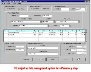
VB project on Data management system for a Pharmacy shop project mainly deals with database management for a pharmaceutical shop. Medicines that are available in the shop are initially stored in the database. Data stored in the tables are connected to the main program using Visual Basic program. VB-project-on-Data-management-system-for-a-Pharmacy-shop.

Front end GUI is created using Visual Basic which is the better programming atmosphere for business applications. Microsoft Access is the database running in the back end.GUI is provided for database management. 

There is lot of scope for future development for  Data management system for a Pharmacy shop project. With few modifications to the code, BAR CODE facility can be included. This project will be best choice for students looking for database project for a first time. 

This document provides entire information of the project with block diagrams, Data flow diagrams and GUI features.

System Requirements for developing VB project on Data management system for a Pharmacy shop project 

The system services and goals are established by consultation with system user. They are then defined in details and serve as a system specification. System requirement are those on which the system runs.

Hardware Requirements:

  • Computer with either Intel Pentium processor or AMD processor.
  • 128MB DDR RAM
  • 40GB hard disk drive

Software Requirements:

  • Windows 98/2000/XP operating system.
  • Microsoft Office package.
  • Microsoft Visual Studio 6.0

Prepaid Water Control Circuit System for Water Metering

A water meter is a device that is used for measuring the volume of water used. This Prepaid Water Control Circuit System for Water Metering Project Report for water metering is basically a control mechanism that only allows usage of water only when there is water i.e. certain required amount of prepaid units in the control circuit system and stops the flow of water once the units are finished.

prepaid-water-control-circuit-system-for-water-meteringThis project offers a lot of advantages. It reduces the metering costs to a great extent. The municipal corporation will be able to compute its income as the prepaid units are employed. Furthermore there will be no complaints from the consumers concerning overcharge and over dues.

Description:

To design this project- A prepaid water control circuit system for water metering, a valve is designed which is electrically operated. This is used to regulate the water flow for the consumer. A sensing system is also made that generates an equivalent voltage corresponding to the amount of water used by the consumer.

For implementing this project, the consumer has to buy a separate prepaid card and the value of credit units encoded into it. These units are then loaded into the control unit of the metering circuit. This controlling circuit is responsible for regulating the water flow i.e. it will allow access of water only when recharge units are present and stops in the absence of recharge units.

Conclusion:

The project discussed here shows successful implementation of designing prepaid control circuit system for water metering. In the future, the design can be further modified to incorporate security information such as an exclusive but similar serial control circuit which can be used for a specific control circuit. While implementing this project, it must be ensured the control circuit must be installed at least one meter from the ground.

Download Prepaid Water Control Circuit System for Water Metering ECE & EEE B Tech/ BE Final Project Report and Document.

Electronics Project Automatic Bike Controller Using Infrared Rays

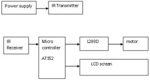
The project “Electronics Project Automatic Bike Controller Using Infrared Rays” is implemented by using an electronic circuit, a microcontroller. The reason for using a microcontroller is that is a very advanced circuit. The microcontroller forms the processing part which receives data from receiver via a remote controller. It then compares the lock and unlocks logic for programming the microcontroller. The LCD display containing data and pulses is fed to the driver circuit of the bike and desired output is obtained.

      electronics-project-automatic-bike-controller-using-infrared-rays The transmitter used is infrared transmitter which is remote controlled. It is used to transfer information to the carrier and to launch a cycle modulation by changing the serial code. They use modulated square wave for their communication. The output is low when there is carrier but it is high when carrier is absent.

          The Automatic bike controller using infrared rays project is fabricated around the microcontroller. It is high power device consuming low power and has a programmable memory. The signal generated by the microcontroller is weak in nature and is passed through the amplifier for amplification. This amplified signal drives the output i.e. motor in this case.

               The display unit is LCD which displays required information like Starting set point. It is very important as lock of Automatic bike controller. This project utilizes 5 V and 12 V voltage supply. 5 V is given to the microcontroller and IR receiver. This voltage is stepped down from the mains with the aid of a transformer.

Conclusion: 

         This project is implemented for a bike controller here but it can be expanded to apply at home devices. Another way to implement this project is to use it as a TV remote. Furthermore this project can be expanded  in the future and create remote control electronic devices formulated for security

Download Electronics Project on Automatic Bike Controller Using Infrared Rays.

ECE Project Automatic Night Lamp with Morning Alarm

ECE Project Automatic Night Lamp with Morning Alarm employs the principle of using transistor as a switch. This system eliminates the need of manual work totally. It switches ON automatically once the sun reaches below visible region. This is initiated by LDR which senses the light similar to eyes. This system reduces energy consumption unlike street lamps which don’t switch OFF even in daylight.

       automatic nigt lamp with morning alarm summaryThe main components of this project are LDR and a transistor. The resistance of transistor changes according to the light received by it. LDR serves as the biasing resistor of this circuit. The power supply required is 12 V, 750 mA supply. A step down transformer is used to get the required voltage from the mains.  

Project Description:

               The project Automatic Night Lamp with Morning Alarm System makes use of a super bright LED as the night lamp. It is powered by a standard 0-9 V transformer. In case of power failure, battery backup is also provided which keeps the circuit in active mode. Light-dependant resistors or LDR’s are used for sensing the darkness in the room.

         Once the bedroom light is switched off, the LDR’s resistance becomes minimum and the LED glows. This LED provides a bright yet cool light. In the morning, the sensor detects the sunlight and switches off along with an alarm that goes ON. The circuit in the project can be easily assembled on a PCB. Also, he speaker should be a small one to make the circuit compact.

Conclusion:

              The project described here has got high sensitivity and depend on light intensity for its working. Its other advantages are its low cost and reliability. No manual operation is required and loads up to 7 A can be handled. However it also has manual mode of operation too. This project can be applied at a variety of places like bedrooms, hostels hotels. Also to save electricity it can be applied to street lamps and gardens.

Download ECE Final Year Project Report on Automatic Night Lamp with Morning Alarm.

Final Year Electronics Project Automation of Network Protocol Analysis System

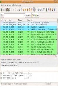
This project “Final Year Electronics Project Automation of Network Protocol Analysis System” which provides open source tools for developing software products into the networking domain. Wireshark, an example of an open source tool is used to analyze the packets and analyze its contents when such packets are broadcasted out of a system. Thus in a nutcase it is a measuring device and is used for examination of traffic of a network cable.

       This project automates the entire process beginning from sniffing of the packets till the validation. The logging part is automated through a C program. The network packets are stored in pcap format. Success or failure of the project is determined by the parsing logic. This logic can be further extended as per project requirements.

Project description:               

                   final-year-electronics-project-automation-of-network-protocol-analysis-systemThe main objective of the project Automation of network protocol analysis is to eradicate human effort and replace it with an efficient system that is automated to analyze network packets. The designed system comprises of a client as well as a server module. Client communicates with the server via an option. This option entered by the client calls an equivalent function. These functions are based on 3 types of logics.

              The logic corresponds to UDP, SIP and QOS parameters respectively. Another component is performed which serves to transform raw packets of data to pcap format by means of appending pcap header. The parsing logic is implemented by UDP and SIP modules. The result be it success or failure is given back to the client. QOS module is used to display the speed and delay which are classified as network performance parameters.

Conclusion:

    This project is used by network administrators to troubleshoot network problems and by network engineers to analyze security issues. The project gives a detailed list of software requirements that indicate functional as well as non-functional requirements.

Download Final Year Electronics Project Report on Automation of Network Protocol Analysis System

Customer Complaint Management System Project

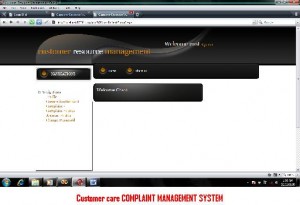
Computer science students who are interested in developing customer care related project, Customer Complaint management system project can be one of the options for selecting a project.Customer-Complaint-management-system-project

The main idea for developing this project is to replace existing manual customer service with a computerized customer service system in a telecommunication company. 

In order to provide better customer support for any telecom company customer support system should be effective. This system will increase company reputation by providing better services and request feedback from customers. As we know customers are key for identifying problems. 

Introducing Customer Complaint management system in to any organization can improve their services like.

  • Handling complaints from customer in a better way.
  • No chance of duplicate complaints.
  • Can provide standard services for a community.
  • Decision making at administrative level will be of higher standards. 

In present market scope for using this project is high. This application provides WAP services for customers through these service customers can use this system on mobiles, this feature can save time. As the information technology is growing widely, developing and maintain this application can be done with a minimum cost. This application can reduce 4 times the cost compare to the existing manual system. 

For more information on complaint management system you can download project report from this site for a free of cost. 

Customer Complaint management system document contains. 

System Analysis

Software Requirement Specification

Feasibility Study

Architectural Design

System Implementation

Screen Shots and Coding.

Automatic Railway Signaling System Final Year ECE Project

Railway security is a very important aspect for a safe and secure transport system and ease for the passengers in travelling. However many challenges have to be overcome before this goal is reached. The project at hand titled “Automatic Railway Signaling System Final Year ECE Projectpaves the way for safety and security.

                 automatic-railway-signalling-system-final-year-ece-projectThe security is ensured in four steps. First is the automatic opening/closing of the gates with the help of sensors placed at a few meters from the crossing roads. A controller is placed to coordinate the signals received by sensors. Then there are red and green signals for the train driver to proceed or halt. These signals are managed from the central control room.

Project description:

       In the project Automatic railway signaling system, the opening and closing is coordinated by reflection sensors. These reflection sensors are placed at a few kilometers from the crossing roads. The sensors transmit this information to the embedded controller which is connected to the gate. On the basis of signals received by the sensors, the controller operates the gates. 

         The protection of the track is ensured by providing a closed loop. If any crack exists then the loop is open and control room sends a sign to stop the trains from moving. The status is given by a LCD which shows the status of the gate. If there is problem with the track, buzzer will activated or else not.

Conclusion:

      This project has been successfully designed and tested. All the working parts of the project have passed scrutiny and after careful selection have been integrated then the project assembled. There is a lot of future scope and developments where add-on features can be included. Highly advanced ICs have been incorporated in the project for best performance.

Download Automatic Railway Signaling System Final Year ECE & EIE Project.

Automatic Foot Dust Vacuum Cleaning Machine ECE Project

The goal of this project “Automatic Foot Dust Vacuum Cleaning Machine ECE Project” is to create a modernized and automatic process for cleaning the foot dust accumulated. This project is useful for use in hospitals, malls, and theatres etc where a lot of people are present. By putting the foot in the machine the dust is cleared automatically.

      automatic-foot-dust-vacuum-cleaning-machine-ece-projectThis project elucidates a simple mechanism which can be easily operated by people. The size of the device is small and compact and hence can be transferred from one place to the other easily. It provides brushes for cleaning and is designed safely so that even children can use it.

Project description:

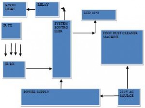
             The ECE & EEE B Tech/ BE Final Project Report and Document makes use of an automatic sensor. Supply of 230 V ac is provided to the single induction phase motor which runs at its usual speed. The pulley of this motor is connected to the pulley of the main shaft via a belt drive. The main shaft’s rotation depends upon speed of motor and dimension of the pulley.

            Two brushes are mounted on the main shaft and they rotate because of the rotation of the main shaft. These brushes actually clean dust from shoes or foot.  The monitoring and controlling action of the entire system is coordinated by microcontroller. If there is any sort of obstacle, IR sensor gives a signal to the microcontroller which increases its count by one and this gets displayed on the LCD.

Conclusion:

               The main advantages of this project are that it eliminates manpower and decreases the operating time. Polishing can also be done t the same time. The design is simple and can be fabricated with ease. The expenditure incurred is also less. As specified above, it can be used in places where large numbers of people move i.e. at hospitals, museums, auditoriums, schools, etc.

Download Automatic Foot Dust Vacuum Cleaning Machine ECE Project.