Automatic Video Surveillance System AI & IOT Project

Surveillance is an integral part of security. The main objective of the Video Surveillance system IoT project is to build an effective system that can be used across different domains and technologies. The system is used to Detect Human intervention and breach in personal or commercial property of the user in real-time using AI and IoT.

It helps users to secure their property with the help of advanced artificial intelligence. The resulting system is fast and accurate, thus helping users with more secure surveillance systems.

For the most part, the job entails looking out for something undesirable to happen. The application is to have a system that provides real-time monitoring and alert security when a human is detected in a user’s property in their absence.

OBJECTIVES:

The main objective is to build an effective Video Surveillance System that can be used across different domains and technologies. The system is used to detect people trying to breach security in the personal or commercial property of the user in real time and send a message along with a short video clip to the user. 

PURPOSE OF EXISTING SYSTEM:

Currently, the existing Rocker Bogie Suspension Systems Project or surveillance robot for defense Surveillance systems can keep video recordings of homes, offices, banks, and so on. But that is useful only after an incident or robbery happens. No Real-time Updates are provided when there is a breach in real-time. 

Just imagine, You’re at your home and someone breaks security and stole money or goods from your office or property. Or consider you’re out of town for some days and there is a robbery at your home. So after you come back home or someone identifies it after some time and they will update you about the breach at your place.

You can take any action after a breach has been done, not at the time it is being done. That issue will be resolved in our system with real-time monitoring and updates.

SCOPE OF SYSTEM:

The Video Surveillance System can be implemented in any residential, Industrial, or commercial property. The system recommends detecting any human intervention on the user’s property and sends a notification along with a threshold of a 10-second video clip immediately as soon as it detects humans.

PROBLEM DEFINITION:

This Video Surveillance System project aims to develop an advanced Surveillance system that can keep on monitoring homes, offices, banks, and so on. With the help of this, you can find out if anyone breaches your security in your absence. We have to simply integrate our system into users existing surveillance systems. 

Module specification: 

  1. Raspberry pi
  2. Camera
  3. Server
  4. SNS
  5. S3  

Need Of Modules:

  • Raspberry pi as a Client to send frames to the server.
  • Camera to capture live video streams.
  • Server for processing frames and detecting humans.
  • SNS sends a multimedia message to a user when someone tries to breach security.
  • S3 to store a short video clip of the breach and send it to the user.

Non-Functional requirement.

EFFICIENCY REQUIREMENT :

When AI is taking care of your property then customers can relax and not have to worry about their security.

RELIABILITY REQUIREMENT :

 The system should provide a reliable environment for both the client and the server.

USABILITY REQUIREMENT :

The system is designed for a secure environment and ease of use.

IMPLEMENTATION REQUIREMENT :

Implementation of the system with pi, night vision camera, python, machine learning, and AI.

DELIVERY REQUIREMENT

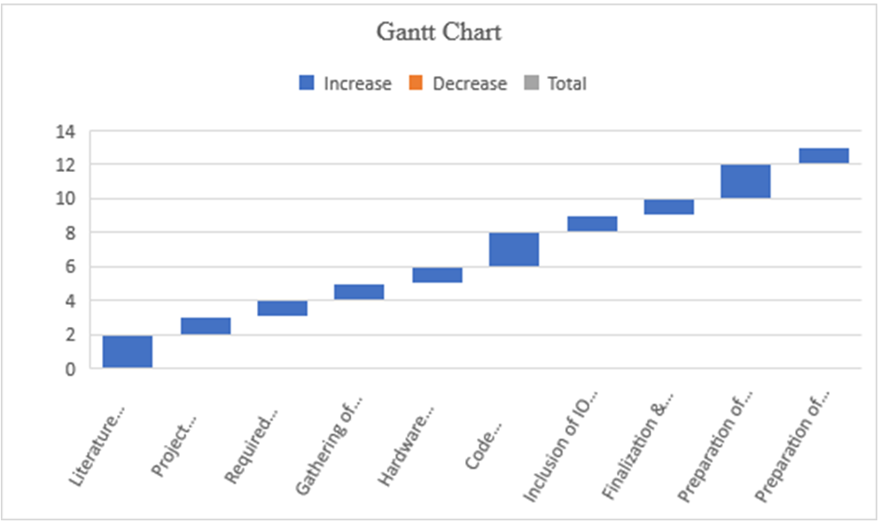
The whole system is expected to be delivered in four months of time with a weekly evaluation by the project guide.

Limitations of the System:-

False Positives

Due to different light variant conditions and camera resolutions, sometimes the system detects humans as false when there is none but that can be neglected if there is a human and the system doesn’t detect it then there should be a problem.

Limited Processing Power

As we are using a microcontroller to send feeds to the server, it cannot handle multiple feeds at once and will be slower as the device increases.

Download Automatic Video Surveillance Management System Project Python Code, Documentation & report, Paper Presentation PPT

IOT Solution for Vehicle Maintenance and Report Generation System

INTRODUCTION

  • Many automotive manufacturers are now moving towards an IoT platform for manufacturing and for service purposes.
  • The main advantages of using IoT in cars are Optimized maintenance and logistics.
  • Our idea is to monitor vehicle status (fuel, efficiency/Km, battery, oil levels, etc..,.) to the customer as well as the manufacturer.

CONCEPT

  • The main aim of every car manufacturer is to increase the life of the car and it’s crucial to maintain the car in a good condition to achieve it.
  • Many problems in vehicles arise due to improper maintenance. Many lose track of their service status and it’s a tiring process to keep in touch with every customer in a large automotive industry.
  • If we maintain a system, that automatically updates the vehicle’s conditions periodically to a specified server, and the system will generate a report, that will be forwarded to the customer and the service team, a lot of manual work will be removed.
  • We as a team provide an IoT solution for vehicle maintenance and report generation system.

FLOW DIAGRAM-FUNCTIONAL DECOMPOSITION

  • Our Vehicle Maintenance and Report Generation system collects data from the sensors available in the car itself and reports it to a transceiver module(ESP8266) which is connected to a database in the cloud.
  • when new data is updated/inserted into the table an event is triggered. This event updates the information in the dashboard, which will be displayed to the customer and manufacturer.
  • Then a weekly/monthly/yearly report generation event is triggered, which will mail the report to the specified recipient.

FUNCTIONAL DECOMPOSITION

Data collection:

The data is collected from the sensor stream of the car. This data is redirected to the ESP8266 module. The ESP8266 is connected to the server, that is allotted to the car. The ESP8266, when all data is collected, converts it into a JSON file. Then the server sends a post request to the server.

Event trigger:

Many database servers provide pl/SQL-based triggers. Here an Update and Insert trigger is created for the table. Oracle server provides a wide range of PL/SQL functions. The IP of ESP8266 is connected to the oracle server, which on periodic updates in the table triggers an event.

Dashboard:

The dashboard is created using HTML and CSS and deployed in the cloud using the NODE JS framework.

FUNCTIONAL SPECIFICATION

Hardware:

ESP8266 CP2101 module(CAR)
ESP8266 CP2101 module(HOME)

Programming Language:

SQL
Javascript (Node JS)
C++(Arduino .ino)
HTML CSS

Dashboard

The Vehicle Maintenance and Report Generation System dashboard are developed using Adafruit.io. This website provides dashboard development for MQTT-based devices

Cloud and IoT Based Health Monitoring System Project

Objective

Our system is useful for monitoring the health system of every person by easily attaching the device and recording it.

We can analyze patients’ conditions through their past data, IoT sensors are being utilized to consistently record and monitor health conditions and transmit alerts in the event that any uncommon signs are found.

If there should be an occurrence of a minor issue, the IoT application additionally has the arrangement to recommend a medicine to the patients.

Introduction

This project is the solution to be able to make use of IoT sensors and actuators to be able to detect issues with subscribed patients remotely to be to monitor health, emergencies, statistics, etc, This makes use of Cloud, Machine learning, IoT platforms, and devices.

The results can be recorded using Arduino.

The doctors can see those results on an application. The system will also generate an alert notification which will be sent to the doctor.

Literature Survey

  • Smart Health Monitoring Systems: An Overview of Design and Modeling
  • Cloud-Based Privacy-Preserving Remote Monitoring and Surveillance
  • A Review of Machine Learning and IoT

Architecture Design

The Flow diagram for Cloud and IoT based Emergency response system follows Sensing, Processing Unit, Cloud Server and Analysis.

Hardware  and Software Requirements:

Arduino: 

IoT Sensors: The main purpose of sensors is to collect data from the patient’s body and from the surrounding environment. 

Cloud: These cloud computing platforms are used to store the data and perform some analysis on the data which is stored on the cloud.

Product Perspective

User Classes and Characteristics

The main objective is to design this System with two-way communication i.e. not only the patient’s data will be sent to the doctor through SMS and email in emergencies, but also the doctor can send required suggestions to the patient or guardians through SMS or Call or Emails.

The user base for this application involves patients and old age people.

Assumptions and Dependencies

Appreciable accuracy in IoT sensors to fetch accurate data. 

Reliable internet connections. 

User Interfaces

Front-end:

  • Web application
  • IoT sensors

Back-End:

  • Open Source IoT platform

Functional requirements

  • Sensors frequently detect data from patients.
  • Collected information is updated in the cloud.

Performance Requirement

The data analysis and communication (response) between the user device and subscribed user must be quick.

Conclusion

The primary purpose of a  health monitoring system is to allow people to lead independent and active lives in their familiar home environment while ensuring continuous, non-invasive, non-intrusive, and seamless surveillance of their health and physical well-being. Continuous monitoring of health status can provide comprehensive information about individuals’ health status over a period of time.

Download the complete project Code & paper Presentation of Cloud and IoT Based Health Monitoring System Project.


Implementation of E-voting Machine Project using Python and Arduino

INTRODUCTION

Our E-voting Machine project is very useful, This Project was implemented using Python and Arduino. The user is no longer required to check his register in search of records, after the voting procedure gets over, the admin will be able to calculate the total number of votes in just one click since the entire work is done using computers. The user just needs to enter his/her unique voter ID.

In today’s world, no one likes to manually analyze the result after the voting procedure gets over because the process is time-consuming and of which results get usually delayed. Everyone wants his/her work to be done by computer automatically and displaying the result for further manipulations. So this E-voting Machine project is about providing convenience regarding voting.

OBJECTIVE

  • Our objective for the E-voting Machine project is to make a user-friendly Electronic Voting Machine that makes the current voting process faster, easier, and error-free.
  • We have used Arduino in our project for the implementation of push buttons and Python as a programming language.

PROBLEM STATEMENT 

The problem statement was to design a module:

  • Which is a user-friendly E-voting Machine
  • Which will restrict the user from accessing other users’ data.
  • Which will ease the calculations and storage of data.
  • Which will help the jury to declare the result without any biasing.

FUNCTIONS TO BE PROVIDED:

The E-voting Machine system will be user-friendly and completely secured so that the users shall have no problem using all options.

  • The system will be efficient and fast in response.
  • The system will be customized according to needs.

FOR e-VOTING SYSTEM

  • (Check
  • Store
  • )

SYSTEM REQUIREMENTS

  • Programming Language Used: Python, C
  • Hardware Used: Arduino UNO
  • Components Used: Push buttons, Connecting Wires, Resistances(100k ohm), Breadboard
  • Software Used: Anaconda 2.7.x, Python 2.7.x, Arduino IDE
  • Modules Used: Serial, SQLite, Tkinter, tkMessageBox

WORKING

  • The user has to enter his/her ID in the system.
  • After verifying the user ID, the system will show a message that whether a user is eligible to vote or not after checking his/her details stored in the system.
  • A message will be displayed accordingly. The user will then have to press the button against which the name of the candidate is written and whom he/she wants to vote.
  • The votes hence are stored in the database and the results will be announced accordingly.

FUTURE SCOPE OF THE PROJECT

My project “e-VOTING SYSTEM” will be a great help in conducting voting at various organizations. So the modifications that can be done in our project is to add one major change which can be done in this project is to add the data of the voters. This will result in the total identification of the voter.

CONCLUSION

From this E-voting Machine project, we can conclude that this program is very useful in conducting the voting procedures smoothly. It provides easy methods to analyze the voting result. It helps in conducting faster, more secure, and more efficient voting. The program can be used per the norms of the voting requirements.

Download the complete project code, report, and PPT on E-voting Machine using Python and Arduino.

Two Wheeled Self Balancing Robot Minor Project Synopsis

Introduction

The basic working principle behind a self-balancing robot is an inverted pendulum concept model in control theory, according to which the robot drives the wheels in the direction in which it tilts. Examples of the inverted pendulum in certain real applications include rockets like MAXUS, Segway the personnel transporter, and a self-balancing vehicle.

It has great advantages like small size, flexibility, and low cost because of these advantages, it can be used in various applications in the field of control engineering. The inherent complexity associated with the control of this platform finds its application in the design and development of control systems for automobiles, spacecraft, and transportation facilities including military transport.

The developed hardware is used to develop an object-carrying vehicle that can be used to reduce human efforts in working places, offices, and household applications.

This is a cost-effective solution using the PID algorithm for these two-wheeled vehicles.

Rationale

Because of the previously stated advantages that come with a two-wheeled self-balancing design, a number of consumer products have recently gone mainstream that utilize a similar idea for purpose of convenient human transportation, i.e. – Hover-boards, Segway, and self-balancing two-wheelers. Our goal with this project was to demonstrate the balancing mechanism used in these products in a compact, cost-effective prototype of a self-balancing robot.

Objectives

1. To balance the whole body on two wheels automatically by designing the best possible structure for the body and obtaining the filtered values from the gyro and accelerometer sensor i.e. – mpu6050.
2. To use inbuilt Wi-Fi or Bluetooth capabilities of ESP32 microcontroller to communicate with the robot in order to de- liver the commands to follow.
3. To fine-tune custom PID values for the robot to ensure its smooth maneuverability.
4. To generate the ability to balance and maneuver with objects placed on its head

Feasibility Study

1) Feasibility of the project

The project is intended to explain the design along with the construction and control mechanism of a two-wheel self-balancing robot. To deal with the problem of sudden horizontal movements and gyro drifts in sensors, a complementary filter is implemented[1]. PID (proportional integral derivative), is the feedback mechanism used for this project.

2) Need of the project –

1. Its ability to turn on the spot and sustainable architecture increases its applications in industries.
2. It is essential for the robot to not only balance but also maintain its position, withstanding external forces or unexpected disturbances if any

3. Active research on two-wheeled robots has been widely increased since the early versions of the studies on self-balancing robots by JOE and n-BOT.

3) Significance of the project –

These robots can be used for

1. Smart gardening purposes.
2. Autonomous trolleys in malls, hospitals, and airports.
3. An intelligent robot for various industrial-military purposes.

4. Currently popularized as “Segways,” these machines are mostly used for travel and tourism purposes and by private security services. It has been put to use by a range of private and military organizations since its invention.

Methodology/ Planning of work

The main objectives of a system for Online voting system are:

1. The objective of the Online voting system is to help the organization in automating the whole manual processing of the existing system.
2. Test the working and compatibility of all electronic components (mpu6050 and motors and its driver) with ESP32 separately and ensure the proper working of each component. a rudimentary prototype using all components with temporary wiring on the breadboard in order to test the integrated working of the components with each other (without tuning PID values).
3. Fabricate the basic frame of the robot using acrylic sheets, spacers, screws, and angle brackets.
4. Mount all electronic components onto the frame.
5. Make wired connections according to the planned circuit.
6. Upload code to ESP32 from Arduino IDE.
7. Update PID values.
8. Test the performance, balance, and maneuverability of the machine, if not satisfied with its performance, go to the 7th step in order to fine-tune PID values else the required development of the robot is completed.

Facilities required for proposed work

Software Requirements:-

1. Arduino IDE

Hardware Requirements:-

1. Arduino IDE
2. ESP32 microcontroller – 1
3. MPU6050 sensor – 1
4. Bo geared motors – 2
5. L298N Motor driver -1
6. 3.7v 18650 Li-ion battery – 2
7. Assorted Jumper Wires
8. 3mm Acrylic Sheet
9. 65mm Nylon Tyres – 2
10. Angle Brackets – 2, Spacers and Screws

Smart Agriculture System Project on IBM IOT platform using NodeRed framework

Project Scope

We need to follow these steps to complete our Smart Agriculture System Project:

  • Project Planning and Kickoff
  • Explore the IBM Cloud Platform
  • Connect the IoT Simulator To the Watson IOT Platform
  • Configure the Node-red to Get the Data From the IBM IoT Platform And Open Weather API
  • Building A Web App
  • Configure Your Device to Receive The Data From The Web Application And Control Your Motors

Our Project’s main aim is to help farmers to control their motors from home. He/ She can On and Off his motor by using his mobile phone.
By using Weather API he can know the weather conditions like temperature, humidity, and soil moisture.

Project Background:

  • This Smart Agriculture System Project mainly aims to help the farmers to ease their work.
  • Farmers can get real-time weather conditions by using smart agriculture.
  • Instead of physical devices we create devices in the IBM IoT platform and use them in our project.
  • We connect our device to the IBM node in the NodeRed framework.
  • We need to create a Weather API account to configure the weather API Platform.
  • We then Configure our Node-red to get the weather forecasting data using HTTP requests.

Project Schedule:

  • Project Planning and Kickoff
  • Explore IBM Cloud Platform
  • Connect The IoT Simulator To the Watson IOT Platform
  • Configure The Node-red To Get The Data From IBM IOT Platform And Open Weather API
  • Building A Web App
  • Configure Your Device To Receive The Data From The Web Application And Control Your Motors

Project Requirements:

  • IBM Cloud Account and IBM Watson IOT Platform to create device and sensor
  • Python IDE
  • Node-Red
  • Open weather API Platform

Functional Requirements:

  • Measure Temperature.
  • Gauge Temperature.
  • Gauge Humidity.
  • Gauge Pressure.
  • Weather API.
  • Display the sensor readings using the Watson IOT sensor.
  • Respond to sensor readings and send alerts to the user.

Technical Requirements:

IoT Simulator

Software Requirements:

  • Python
  • Node-Red
  • IBM Watson IOT Platform
  • Open Weather API

Project Deliverables:

A Smart Agriculture System web App for farmers where he can:

• Monitor temperature, humidity, and Soil moisture along with weather forecasting details.
• Control motor for watering the crop through the web app from where he was.

THEORETICAL ANALYSIS

  • Required Software Installation
  • Node-Red

Installation:

  • First, install the Node
  • open command prompt
  • Type ->npm install node-red

To Run the application:

  • open command prompt
  • And then type “node-red”
  • Now open http://localhost:1880/ in the browser

Installation of IBM IOT nodes and Dashboard nodes for Node-Red

  • In order to connect to the IBM Watson IOT platform and create the web UI, these nodes are required
  1. IBM IoT Node
  2. Dash Board Node

IBM Watson IOT Platform

  • Steps To Configure:
  • Create an account in the IBM cloud using your email ID
  • Create IBM Watson Platform in services in your IBM cloud account
  • Launch the IBM Watson lot Platform
  • Create a new device
  • Give credentials like device type, device ID, Token
  • Create API key and store API key and token elsewhere

Python IDE

  • Install python 3 Compiler
  • I Installed PyCharm Community Edition 2020

IoT Simulator

 In our project in the place of sensors, we are going to use a lot sensor simulator which gives random readings to the connected

OpenWeather API

Building Project

Connecting IoT Simulator to IBM Watson IOT Platform

  • Open link Provided in section 4
  • Give the credentials of your device in IBM Watson IoT
  • Click on Connect
  • My credentials given to the simulator are:
  • Organization ID:ka1gns
  • Device Type:nodemcu
  • Device ID:1234five6789
  • Authentication Method:use-token-auth
  • Authentication Token:*********
  • You, Will, receive the simulator data in the cloud
  • You can see the received data in Recent events
  • Data is received in this format (JSON)
  • You can see the received data in cards by creating cards on Boards Tab

4.2    Configuration of Node-Red to collect IBM Cloud Data

  • The Node-Red IBM IoT App is added in Node-Red Work The appropriate device credentials obtained earlier are entered into the node to connect and fetch the device to Node-Red
  • Once it is connected Node-Red receives data from the device
  • Display the data using debug node for

Configuration of Node-Red to collect data from Open weather API

  • The Node-Red also receives data from the OpenWeather API by HTTP GET request. An inject trigger is added to perform HTTP requests for every certain
  • The data we receive from OpenWeather after the request is in JSON format

Configuration of Node-Red to send commands to IBM Cloud

  • By using IBM IoT out Node I used to send data from Node-Red to IBM Watson So, after adding it to flow we need to configure it with the credentials of our Watson device.

Adjusting UserInterface

  • By connecting all the flows shown above
  • We can display our UI by clicking on the dashboard tab in Node-red
  • On the above page, we can display the sensor data and motor
  • On this page, we open weather API data is displayed

Energy Management System Python Project

ENERGY MANAGEMENT

  • This is a project on energy management.
  • The project helps to save energy.

Description

  • First, create an IBM cloud account with an e-mail address and password.
  • Then create an IoT platform and node-red platform.
  • We need to write a python code for it because it is a real-time example.
  • Create an MIT app.

First, create an IBM cloud account with an e-mail address and password

Go to google and search for IBM and create an account using your email address and log in to the page. we will get the interface as an IBM dashboard.

CREATING IBM PLATFORM

After creating an IBM account there will be a search option then we can able to see it. Type Internet of things there will be a platform called the internet of thing in that u can able connect the so many services in that internet of things and create a service in that it will ask u to launch it and for creating an internet of things u need some keys as API keys, Device connects and so many things will fill and u can able to see an option as the add device click on new device u can see the device has been created for that u need to keep the API keys, Device information safely in the note pad because it will help u at the need for connecting it.

WRITE PYTHON CODE

we are writing python code because we are going to deal with a real-time example so we need to use python. actually, our project is about how much electricity is causing monthly and its estimated cost
In this, we are writing about fan, light, washing machine, tv, and ac let s take some random values in that because we can’t able take the exact values, and then we need to add all of the to know the charge and then we need to find out the estimation money for it. after completion of this code, u can able to know the code is running.
we need to send it to the IoT platform so we need to install pip by command prompt and then write the code separately so u can able to run and send information to the IoT platform. For sending to the IoT platform we need to give information in a notepad.

python code:

python running code

Information on IoT platform

Creating node-red platform

For creating a node-red platform we need to search in IBM as a node-red app then u can able to see the node app then create it as the local u can create node-red is nothing but we will get the information in the form of a flow chart.
we need to install IoT in, IOT out will be in the node-red app itself and then u can able to use it for better ability and experience we will use the gauge tool and for doing it on the web we will use the HTTP in, HTTP response and then we will use the payload option to print in and I will show u the flow chat I had created and when we run the program u can see the outputs are coming in the debug option.

Create an MIT app.

Search for the MIT app and click on create apps.

First, we should design the app page with alignments given on the left side of MIT. with horizontal alignments drag them to the screen and edit those with suitable markings.
And next insert a text box into the screen. As we have taken energy management the as a fan, ac, light, tv, etc.
Now insert 5 text boxes to the screen and assign the markings. Take two buttons one as checked and another as not checked.

And the two text boxes with one as charge gives the charge of every applicant and another as cost, which gives the summation of all applicants.

This is done and next tap to blocks button. In that create the blocks with URL.

Paste the URL which we have I IBM as:

Now tap on the build option and get the QR code and scan the code you will receive an apk file and install the file and app.

Now the click on the checked button now the values, cost, and charges will be displayed on the screen in their respective blocks.

Intelligent Access Control for Safety Critical Areas Project using IoT Analytics and IBM Cloud Services

Purpose of the Project

  • Access control is done by using a smart Analytic device. It verifies the entry of the person.
  • The Smart device verifies the persons entering into the industry.
  • The details of the person are being taken and uploaded into the cloud.
  • We can Restrict the entry of unknown persons and we can restrict the persons who are not following the safety measures by using this IoT device.

Existing Problem

The Intelligent Access Control problem with the present existing device is it cannot able to identifies the safety measures of the persons it just identifies the entry of the persons.

Proposed Solution

We can make use of IoT Analytics in Access Control, such that during working hours in the industry we can identify the persons who are following the safety measures and who are not following.

 Also, with the usage of IoT, automatically, the details of the person are taken and we can restrict them.

Hardware/Software Designing

The Intelligent Access Control Software design involves general We used IBM Cloud Services to create the Internet of Things platform. In the IoT platform, we create a virtual Raspberry Pi device. After creating the design we get the device credentials. We use these credentials in the Python program then we integrated the Node-Red platform with IoT. With the help of MIT APP Inverter, we designed the app & integrated it with the Node-Red to observe the values.

Experiment Investigation

To complete our Intelligent Access Control project work we collected the required data from Google & research papers. After getting complete knowledge we work according to our roles in the project. At first, we create the IBM Cloud account then we created the Internet of Things Platform after we wrote a python code in IDLE to connect IBM IoT Platform. Next, we created the Node-Red Services. This service helps us to show virtual flow graphs. We connect Node-Red to IBM IoT to get the current, and voltage, and calculate bills. From Node-Red we send values to the MIT APP. From the app, we can view the details of the person.

FLOWCHART

Flow Chart

MIT APP:

MIT App

ADVANTAGES & DISADVANTAGES

Advantages:

1) Increase ease of access for employers

2) Keep track of who comes and goes

3) Protect against unwanted visitors

4) create a safe work Environment

5) Reduce Theft and Accidents

6) Easy Monitoring

Disadvantages:

1) Access control systems can be hacked.

 APPLICATIONS

1) Large Industries

2) In Airports

3) Government Sectors.

IoT based Attendance System Project Using Blockchain and JAVA MySQL

The success of this IoT-based Attendance System app will ensure that many more parents and organizations will be motivated to use this common platform. It becomes complicated when strength is more. With the increase in technology, attendance monitoring is designed with android or web-based applications. However, the intention of this design is to provide a Blockchain-based app that can be downloaded and used by the organization with no third-party control to meddle with the data.

There is an update option to modify attendance when it’s needed. However, the modifications are recorded and tracked, just in case, it’s a fraudulent activity. Attendance is captured using IOT automatically and is entered into the blockchain which makes the data tamper-proof, secure and robust. The privacy of its users is preserved because the user ids are generated by a trusted third party. This data is available for the government for Scholarships and other related decision-making.

IOT-based Attendance System using Blockchain is an application that is made for students and faculty of a particular college to maintain students’ attendance which is captured through an IOT device(biometric) and then the attendance is stored in the Blockchain. Blockchain is used in this application to ensure safety and a tamper-free environment as the data cannot be manipulated and is used for government purposes.

Objectives

Generally, in many institutions attendance is monitored and marked using conventional systems like android or other similar web applications. Few conventional databases do not have features like checking whether any information has experienced unauthorized changes or not. In this system when the data is entered into the blockchain, no one is allowed to edit or delete the data.

This makes the application transparent and different from other web-based attendance systems as IoT is used to capture attendance through biometrics of the students in the class. Students’ poor attendance rate is one of the most challenging problems tackled by college management today. With the help of this application, student attendance rates can be improved which is also helpful for the government to take precise decisions regarding scholarship-like schemes for students with transparent data. Using blockchain and some encryption techniques, this application is made secure from any manipulations.

Student Login Page

Methodology

The fingerprint module will collect fingerprint data from multiple users and sends it over the internet to the website. The IoT-based Attendance System website is coded in HTML, and CSS, JSP has a MySQL database, and records of attendance are stored in Blockchain. By logging into the website, the student can view all their attendance records. The timestamp of students’ attendance is encrypted and stored in the blockchain.

CONCLUSION AND FUTURE SCOPE

This IoT-based Attendance System application helps to automize the attendance system and makes it easy to manage all the data. Encryption, decryption, and blockchain make the application very secure. The application has a very user-friendly UI and is made to keep UI and UX in consideration.

The future enhancement of this IoT based Attendance System application is

  • To use Ethereum to make the application up to date with the technologies
  • To generate automatic weekly and monthly reports

DATABASE TABLES SCREENSHOTS

Tables in the project.
Test case showing the home page after pasting the URL in the browser
Test case showing navbar functionalities working.
Test case showing login is done and navigated to the home page
Test case showing student registration is working.
Test case showing faculty registration
Test case showing faculty registration is working.
Test case showing attendance stored in blockchain

IoT based Attendance System Using Blockchain
Test case showing student’s attendance records.
Test case to get student report
Test case showing Student’s attendance report.
Test case showing download report is working
Test case showing all student details.
Test case showing all student’s attendance records.

Flow Chart Diagram:

Flow Chart

Architecture Diagram

Architecture Diagram

Usecase Diagram:

usecase diagram

Software Requirements

Programming Language: Java
Graphical User Interface: HTML, CSS with Bootstrap, JSP
Libraries: MYSQL connector jar file, Apache Tomcat jar file
Encryption Algorithm: SHA-256
API: JDBC
Framework: Java EE
Tool: Eclipse, MYSQL

Hardware Requirements:

IOT Fingerprint Scanner

Design and Implement a Healthcare Monitoring and Management System IoT Project

Nowadays Internet of Things is bringing a revolution in the infrastructure of technologies. The IoT-based health monitoring system is essentially a patient monitoring system in which he can be supervised 24*7. Remote Patient Monitoring arrangement enables observation of patients outside of customary clinical settings (e.g. at home), which expands access to human services thus bringing down costs. Healthcare is given extreme importance by each country with the advent of the novel coronavirus.

Recently there has been a spike in the use of smartphones and along with that, wearable sensor remote health monitoring has evolved quickly. IoT not only helps in preventing the spread of disease but also in getting a proper diagnosis, even if the doctor is present at a remote distance By facilitating effortless interaction among various modules, IoT has enabled us to implement various complex systems such as smart home appliances, smart traffic control systems, etc.

PROPOSED SYSTEM:

The main objective of this Healthcare Monitoring and Management System is to develop, design, and implement a smart patient healthcare monitoring system. The sensors used here are embedded in the body of the patient to sense the parameters like the heartbeat and temperature. These sensors are connected to a master unit, which calculates all of their values. These values are then transmitted by leveraging IoT cloud technology, to the base. From the base station, these can be easily accessed by the doctor present at some other location. Thus based on the temperature and heartbeat values, the doctor can decide the state of the patient and appropriate measures can be taken.

OBJECTIVE:

Monitor patient parameters remotely to increase the efficacy of healthcare management systems

IDEATION:

We need to monitor the patient parameters from remote distances using various sensors. The data given out by the sensors are then sent over to the cloud for further access via a Wi-Fi module (inbuilt or externally connected). This is being done to reduce the critical time of testing patient parameters before any major operation.

Here we are measuring the temperature and pulse parameters of a patient remotely.

Components required:-

MLX 90614 Temperature
MAX 30102 Pulse Rate
Jumper wires.
Nodemcu ESP8266 board

The Gantt Chart is shown below:-

smart patient healthcare monitoring system

Summary:-

 Health care is given extreme importance nowadays by each country with the advent of the novel coronavirus. Thus in this regard, an IoT-controlled healthcare monitoring system is most probably the best solution for such an epidemic. Internet of Things (IoT) is the new revolution of the internet which is a growing research field, especially in health-related services.

“Healthcare Monitoring and Management System” is the project where we have mainly focused on two objectives first one was a smart health monitoring system, to collect the health history of patients with a unique ID and store it in a database so that doctors need not spend much of their time in search of the report and give analysis right from the dashboard. Any health care that is being done will be updated and reflected in the dashboard itself. And the other one is the Wearable-Sensor-Based Fall Detection System for aged people, to monitor their movements of them, recognize a fall from normal daily activities by using sensors, and automatically send a request or an alert for help to the caregivers so that they can pick up the patient.

However, there are a few shortcomings to this too. Basic knowledge of the operation is to be learned by the caregivers. Also, both the caregiver and the wearer should know how to protect the sensors from water damage or any physical damage. 

  • Planning and project management 

S.No.

Activity

Starting Week

Number of Weeks

1.

Literature Review

1st week of January

 2

2.

 Project Finalization

3rd week of January

 1

3.

Required software setup

4th week of January

 1

4.

Gathering of Hardware & Formation of codes

1st week of February

1

5.

Hardware assembly calibration

2nd week of February

 1

6.

Code Integration & Debugging

3rd week of February

 2

7.

Inclusion of IoT and Blynk

1st week of March

 1

8.

Finalization & modification of Website and mobile application

1st week of March

 1

9.

 Preparation of project report

2nd-3rd week of March

 2

10.

Preparation of Project presentation

4th week of March

1