Develop a Multiple Interface Based Fire Fighting ECE Robotics Project

Introduction to Develop a Multiple Interface Based Fire Fighting Robotics Project:

A monitoring system that is based on the real time is presented in a multiple interface that is usually used in the automation of home. The home and building security system includes security modular, appliance controller module, fire fighting robot, television security device, GSM modem, remote supervise computer and appliance control module.

Industry personal computer is the main controller of the fire fighting robot. In order to control the mobile robot we order the command that acquire sensor data and programmed the supervised remote system with the visual basic. Security information can be received by the robot from the interface of the wireless RS232 and a generate user interface is designed for the computer control of the fire fighting robot.

In the results of the experiments the users will control the mobile robot with the help of the RF controller, remotely supervise computer and supervised control. Obstacle can be avoided by the robot using IR sensors as well as ultrasonic sensors as per the fusion method of the multi-sense. Two flame sensors can be used to know the source of the fire and fight it with the help of the extinguisher. We are also planning to design an obstacle detector in the future modular using the IR sensor and ultrasonic sensor along with the fusion of the algorithm.

For getting more quick and easy environment map in the outdoor and indoor we need to combine the laser finder . Usually a home provides safety of the security of factory, office building and laboratory is necessary to the life of human and we have also created a multi-sensor security based system that includes a robot for fire fighting in the intelligent building we design a fire fighting robot that comes with an extinguishers. 50cm, 80kg and 130 cm are the respective shapes.

Robotic Lanmover Final year Project Based on Robotics with Report

Introduction to Robotic Lanmover Final year Project:

The implementation and design of a robotic lawnmower, yardbot is represented in this paper and the main objective is to craft a lawn mover that can mow the grasses in a specific area automatically within less than 20 minutes. It should also able to avoid collisions with the obstacles that may locate in that area. Usually the obstacles that are present in a lawn and therefore must take into consideration are flower pot, fenced area, table and so on. In case the lawnmower comes in contact with any moving objects then it will engage the mover for 30 seconds and then move off from the field area.

The main motto is to achieve a create a frame and to implement perfect algorithms for the the creation of such a motor. It is also followed by the designing of an efficient, navigational and functional algorithm that can process data from a completely different GPS, ultrasonic sensors, digital IMU , laser range finder and a touch screen. The use of coders and output of algorithms will control the direction and speed of the movement.

It is a tedious job to mow a field using a lawn mower and usually a person tends to avoid it. There are two ways in which you can avoid doing this job firstly by engaging someone else to do the job for you in return of some money and secondly to use a robot to accomplish the task.

Here we are focusing on a complex robotic lawn-mower as the existing simple mower has not been accomplished to create a successful mover that can perform exactly even in complex design fields.  The robotic lawn mower proposed in this project is based on the GPS navigation system and is a sophisticated device that is capable of mowing complex and large size fields. 

ECE Project Report on Autonomous Robots

Introduction to Autonomous Robots ECE Project:

Autonomous is the word which clearly tells that it works on its own without any guidance. Autonomous Robots are those which work independently without any particular tasks or any kind of human guidance. Most of the robots works with some extent of autonomy and these are of various kinds some robots can be of autonomy to some extent and some completely.

The strength and the extent of autonomy is based on the work or task that the robot has to be done for example if a robot has to clean a floor or lawn it some one kind of autonomy and the robots which work in space has one kind of autonomy all these are based on the place in which they work. For any kind of robot the exact work and the kind of work and the place in which it has to work must be determined before as this can be unpredictable.

The most important thing in the research of robotics is they have to enable based on the environment it has work as working on the land and in space has many variations. A complete independent robot has a capability of gathering information regarding the environment and also has the capability of working without human intervention for longer period and also can move its parts or some parts without human guidance.

The autonomous robots are designed in a way that they can avoid situations which are harmful to itself or others. The autonomous robots gains novel abilities such as adjusting the strategies based on the surrounding situation and also for completing its tasks. This paper deals with the autonomous foraging which is an apprehension among the social anthropology, human behavioral ecology and also the robotics artificial life and intelligence.     

Download  ECE Project Report on Autonomous Robots .

Various Images of the GPS Navigation Robot Project

Various Images of the GPS Navigation Robot Project: (Designed In Pro-E) 

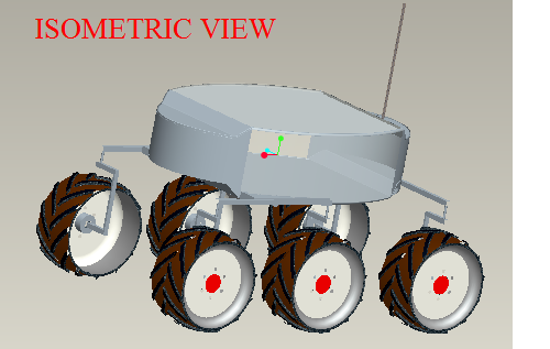
 ISOMETRIC VIEW

ISOMETRIC VIEW

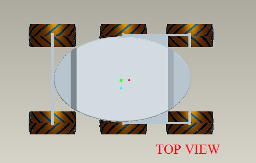
 TOP VIEW

TOP VIEW

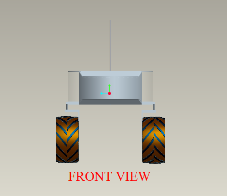
 FRONT VIEW

FRONT VIEW

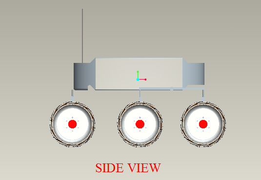
 SIDE VIEW

SIDE VIEW

ADDED FEATURES IN OUR BOT

 Our GPS Navigation Robot Project has its unique code of 16 characters. It is encrypted in the permanenthidden storage memory unit of microprocessor, where it acts as a “black box” of our bot. The entire history is stored in it. It is a separate process which saves only the event history (control signal and direction Total Power Consumption till last update) of 64MB RAM at very high processing speed of 12KB/sec.

 In our Robot the location of memory unit is sent to main processor (ARM 9).when the code is accessed the complete event history is shown to administrator. It enable by performing the separate internet protocol (IP) based server to note the event history.

 The system gets its updation once in two minutes at 12KB/sec .At that time the motor is in OFF state, where the memory management is essential, so it holds nearly 10 to100KB data.

 We are trying to manipulate in most appropriate forms. It is used locate even at remote area.

CONCLUSION:

       Our GPS Navigation Robot Mechanical Project design is cumulative approach of both the electronic and mechanical ideas. It is designed with various references and guidance taken from our faculty, books, sites and journals. We put up our innovative ideas by analyzing serious present day issue, and trying to work out with it.

Mechanical Approach of the GPS Navigation Robot Project

Mechanical Approach:

Kinematics:

The GPS Navigation Robot Project we have designed to traverse on all terrains is on the concept of getting support from all the sides and having the ability to move ahead. The dimensions of the robot are 1600*965*810 mm.                                                     .

Design of Wheels and Motors:

The locomotion of bot is designed with six wheels so that the stability of the vehicle is high and moreover while climbing the steps or moving in rough terrain it will be able to have more support. Wheels of diameter400mm and thickness200mm are used. The wheels with V-THREAD profiles are selected to meet the desired need to move in all terrain. D.C Motors with specification of 40kg torque and 150rpm are designed to meet the desired speed and the load ratings. Similarly in total there are six motors one for each wheel hence each wheel will be having independent drive. The motors are placed in the wheel hubs supported by c-clamps.

Mechanism of Linkage:

          Kinematic of bot has three linkages in total. Each linkage supports two wheels. The front two wheels of each side are connected by one linkage and the rear wheels are connected by another linkage. Each linkage is designed on the concept of Double Rocker Mechanism. According to which there are two cranks connected to the main link. Similarly in this model the two C-clamps which are connected with the main link and the wheel acts like crank. Due to the presence of this type of linkages there is no separate suspension mechanism needed. At all point of times and at all positions always all six wheels will be touching the ground. This is the most advantageous point of having linkages.

 Double Rocker Mechanism

          In the above diagram A and B are the two cranks and c is the main linkage which is shown in the Double Rocker mechanism.  

FIG: shows the linkage in connection with the wheel

Steering Principle:

Apart from six D.C Motors, four servo motors are placed in between the C-clamps and linkage except the two middle wheels. So the wheels can be turned in any direction. The wheels if properly turned to the required angle, the entire vehicle may completely turn in its position up to 360°.The directional gyro which is of electronic model when fixed in the correct axis can find out how much exactly the wheel’s angle is displaced. Hence when the wheel has been turned to the required angle the action from the micro controller can be given to cutoff the voltage to the servo motor there by removing its action.  As each wheel has independent drive hence while turning the differential drive is obtained by giving variable supply to motor.

Material Selection of Chassis and Other Surfaces:

The chassis is the platform for electronic and mechanical tools. The chassis which should be light in weight as well as having high load capacity should be selected. Hence it was designed to use CNC Titanium or EPO resin.

 The two surfaces which are extruded from the chassis are shown transparent in the diagram drawn in the   pro-e modeling. This is due to the fact that both the surfaces are made of a transparent glass fiber made of carbon composite so whatever changes or deformations taking place could also be easily identified and rectified easily. Antenna is placed in the rear end, while the camera setup is placed in the front end. The camera setup has both stereo and C-MOS camera.

Control Architecture of the GPS Navigation Robot Project

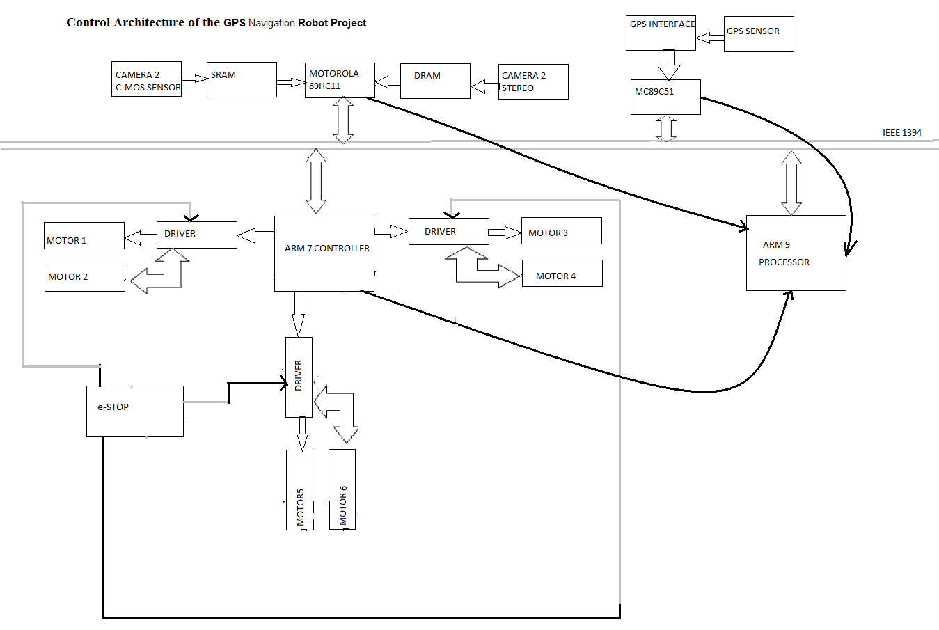
Our GPS Navigation Robot holds a micro processor and three micro controllers for multi task assignment.

The camera action, memory allocation, motor action and GPS way point verification are the synchronous process, where the continuous clock pulse is required.

Here by we use the Control Architecture,

ARM 9 with VME bus based micro processor.

ARM 7, ATMEL 89C51, Motorola 69HC11 are the three micro controllers used for speed and motion control drivers, GPS sensors and E-stop and Image Processing analysis respectively.

All the data has been send through IEEE 1394 fire wire bus controlled at fixed sequence.

Control Architecture of the GPS Navigation Robot Project

GPS Navigation Robot Final Year Mechanical Project

Positioning Sensors Used To Navigate On Rough Terrain:

Global Positioning Sensor:

Constructional Working of GPS:

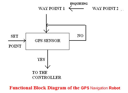
GPS sensor for Navigation Robot is used to navigate the bot reach the fixed destination. Here we use differential gps system, where the carrier frequency is very high even at low signal status certain adaptive methodologies to reach our destination. The functional block shows how the operation is performed by our bot. 

Functional Block Diagram of the GPS Navigation Robot:

 Functional Block Diagram of the GPS Navigation Robot

The block diagram of Final Year Mechanical Project clearly shows the functional working of gps that is here the set point (current position) is compared the first waypoint. Once the destination is reached the program memory enqueue the second way point and so on. If the designated waypoint is not reached again it checks till the destination is reached. 

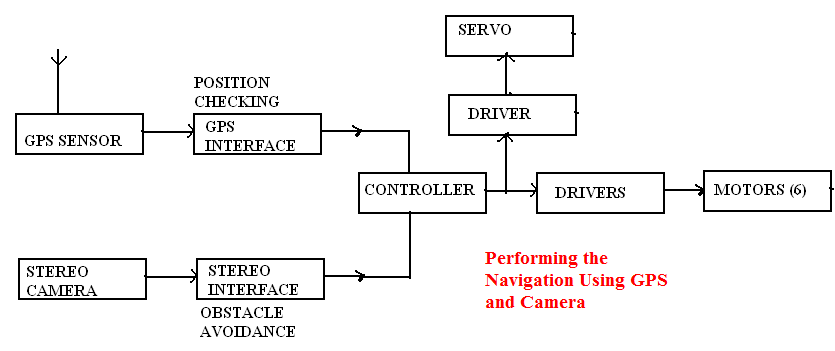
Performing the Navigation Using GPS and Camera:

The effective way of using adaptive robotic technology is performing the complex operation simultaneously to do the desired operation. Similarly we have performed the simultaneous operation by performing both obstacle avoidance and positioning using stereo camera and gps sensor respectively. The main advantage of performing this GPS Navigation Robot operation is maximum nearness error can be avoided that is created during real time positioning. The block diagram clearly shows how the navigation is performed.

 Performing the Navigation Using GPS and Camera

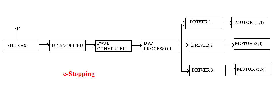
e-Stopping:

we perform the e-stop operation by providing stop signal to the driver .this we attain by converting the availabe frequency (crystal frequency) to PWM signal by using PWM converter .this signal is fed to the motor driver to stop the bot it is be. The block diagam shows the operaton of e-stopping.

e-Stopping

Robotic Project Report and Documentation

The following algorithm for robotic project report & documentation describes the sequence of operation for both lane detection and obstacle avoidance using Image Processing Analysis.

For Lane Detection:

STEP 1: Initialize the camera.

STEP 2: Take the different orientation of the given lane and pre-process the image and store it in the SRAM.

STEP 3: Now allow the camera to traverse the lane.

STEP 4: Take the snap of the lane and check with the data base.

STEP 5: Perform the controller action.

STEP 6: Repeat the process till the destination is reached.

For Obstacle Avoidance:

STEP 1: Initialize the camera.

STEP 2: Observe the environment.

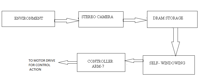
STEP 3: Store that in DRAM.

STEP 4: Do self windowing technique and determine the least pixel rate by using the analysis.

STEP 5: Allow the controller to take the action.

STEP 6: Repeat the process till the destination is reached.

Robotics Final Year Project Ideas and Topics

Constructional Working of Robotics:

Electronic Engineering ECE Approach:

Camera:

In our Robotics Final Year Project we have two cameras

a) C-MOS camera sensor

b) Stereo camera

          The C-MOS sensor camera is placed at the center of the bot and the stereo camera is placed at the center of the bot and the stereo camera is placed at the top of the bot. the camera is tilt to an angle to make the projection perfectly projected to the center of the object.

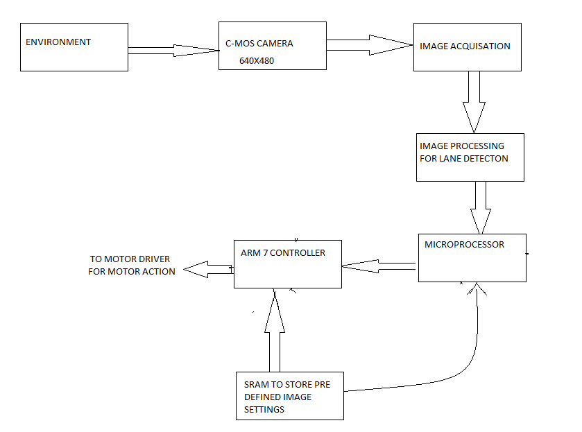
The C-MOS camera is used to perform more specifically for the lane detection. It is used because of its very high sensitivity to light, low power consumption and low cost. The output is digital, so it is directly fed to the controller to take the action. The functional block diagram shows the importance of camera action.

Technical Features of the Robotic Camera:

The Image processing and Image acquisition is performed by the on-board micro processor and the result of stereo and C-MOS camera is stored in SRAM (Static Random Access memory) and DRAM (Dynamic Random Access Memory) respectively.

The lane following is pre processing method, so the sample of images are pre loaded to the SRAM and it’s been cross checked by the controller and necessary action is given to the end effector. 

          The Dynamic image processing is carried out by using stereo camera where the self-windowing algorithm is used for real time variation. It is been stored in DRAM and synchronously signal is given to controller to perform the end- effector action.

Block diagram of the robotic project idea clearly show the importance of two cameras.

For lane detection:

For lane detection

Obstacle avoidance:

Obstacle avoidance

 Stereo camera is used for obstacle avoidance performances, since it has very high resolution.

Mechanical Engineering Projects on Robotics

The computational robotic feature was developed using a mechanical system engineering approach with emphasis placed on the understanding the inter-relationship between system components and on maximizing the overall system performance.

The Mechanical Engineering Project development of fully autonomous is a very complex task which holds the consideration of several factors. First, the appropriate view of providing and utilizing autonomy must be determined for each application. For example, the sensors used in this robotic project for image analysis and global positioning is high a time-variants, so this will directly create impact on any set of tasks designed.

Here we tried to manipulate the entire operation carried out by the Robotics Engineering itself that is it has its own capacity to take any decision under any environment without interference.

The integration is very difficult because it requires the assembly of many complex sub systems into a high degree of interconnection and synchronization.

From a Mechanical and Electronic engineering perspective, a well-defined architect provides the underlay framework for achieving reliable maintainable cost-effective system. N Such architecture does this by enabling methods coherently integrating diverse physical, functional and disciplinary sub-systems.

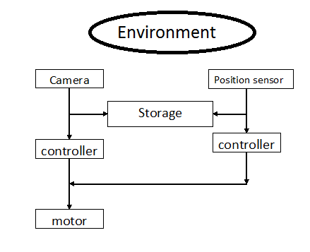
Functional block diagram of our robotic model:

General block representation: 

general

When we analysis these blocks we can acquire the solution for given problem

 environment

The general block diagram of Final year mechanical project clearly shows the importance of sequential operation to perform to attain the targets.

The camera which acts the eye for the bot which captures the environment and dynamically analyze the variation and is stored in temporary storage device and its being compared by the processor and action is given to the motor.