Wireless Petroleum Level Measurement Using Ultrasonic Digital Sensor

Liquid level indicator is a device meant to overcome the stress of opening reservoir or dipping rod into the tank for gauging the level of the liquid. The level indicator can be divided into three stages.

The sensing circuit, wireless transmitter & receiver, control circuitry. The sensing unit is isolated from the measurement & control circuitry.

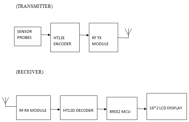
The liquid level information is wirelessly transmitted which is then received at the receiver end. The level is shown on the LCD Interface.

The Petroleum Level Measurement system consists of ultrasonic digital sensors, Encoder IC, RF Transmitter, Decoder IC, RF Receiver, Microcontroller, LCD etc. The percentage of the levels is shown on the LCD Interface.

TRANSMITTER & RECEIVER

Driver Assistant System Using Ultrasonic Sensor

Nowadays, accidents are becoming a common occurrence on the roads due to negligence or excess speed. If we can avoid, it means we can save many lives. The main objective of our Driver Assistant System project is to develop an anti-collision system for vehicles that can be used for real-time application.

The application is based on ultrasonic sensors to detect the main features of the ultrasonic sensor distance projector and the control circuit power supply.

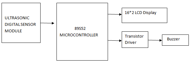
This Driver Assistant System controls the distance between the car and other vehicles or obstacles to come. 89S52 microcontroller performs all operations. The obstacle distance is displayed on the 16 * 2 LCD screen. If the obstacle is in the sensing zone call ring sounds to give a warning.

Measuring the distance of an object in the way a stationary or mobile person, structure or vehicle is used in many applications such as motion control robots, vehicle control, blind stick, medical applications, etc. Measurement with ultrasonic sensors is one of the cheapest among the various options.

In this measurement application of the distance of an obstacle using a digital ultrasonic transmitter, the receiver module and a microcontroller are. The experimental apparatus and the results are described and explained. The ultrasound view shown here is suitable for measuring the distance between 20mm and 4000mm (4m).

SOFTWARE:

1. Keil COMPILER
2. EMBEDDED C CODE
3. ucFlash

HARDWARE:

1. Microcontroller AT89S52.
2. 16*2 LCD DISPLAY
3. Transistor Driver
4. Buzzer
5. Ultrasonic Digital sensor Module

BLOCK DIAGRAM:

Bus Tracking System using GSM Module Project

Bus Tracking System:

Using  GSM Module and Microcontroller we are designing and implementing a time saving system for daily BUS commuters, which will give the information about the present position of BUS whenever subscribed by the subscriber for a particular BUS, which will have its unique code.

Scope of the Project:

  • Bus Tracking System can be implemented in government, company, college & private buses.
  • Can also be implemented using GPS system.
  • Ring can be developed for blind people to get the status of bus.

Brief Description:

In the Bus Tracking System project, an IR transmitter is placed in bus & IR RECEIVER unit is placed at bus stop. Whenever bus reaches bus stop our unit comes to know which bus has been arrived. The transmitter present in the bus transmits a certain code using RC5 protocol. Carrier frequency for RC5 protocol is 36 kHz.

IR receiver which is present on bus-stop detects the IR signals and gives the coded data to the microcontroller for decoding purpose.  Microcontroller is controlling block of the system. After decoding this code, which bus has arrived is decided.   The acknowledgement is given to the system user through SMS. This SMS is send whenever bus is arrived.  The subscriber numbers to whom the message has to be send is stored in the EEPROM, which is the memory element used over here.

The 89s52 microcontroller communicates with EEPROM using I2C protocol. Whenever a message is to send to the subscriber for the subscribed bus controller  fetches those subscribed numbers & then send the message through GSM module. Microcontroller and GSM module are interfaced through MAX 232. . MAX232 is a device which converts TTL voltage logic levels to RS232 & vice versa.

The GSM module sends SMS to the subscriber which is mentioned in EEPROM through AT commands.  AT commands are used to send SMS from GSM module. LCD is used to display which bus has arrived.

The block diagram:

HARDWARE REQUIREMENTS:

Sr. No. Components Specifications Quantity
1 Microcontroller 89s52 1
2 MAX 232 IC DIP 16 PIN 1
3 GSM Module SIM 300 1
4 EEPROM CAT 24WC 08 8KKBit Serial CMOS 1
5 IR Transmitter Phillips RC-5 (Carrier Freq 36 KHz) 1
6 IR Receiver TSOP 1840(fo-40khz) 1

Motion Sensor for Security Light

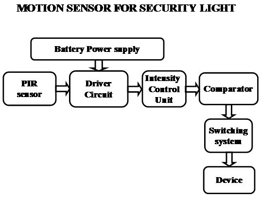
The Motion Sensor for Security Light system uses Passive infrared sensor. These sensors are capable of sensing the presence of human being and post the same to the comparator IC. Now the micro comparator takes the responsibility of processing and judges the status of individual appliances and there by controls them using switches like relay, TRIAC.

The most important thing to be noticed here is the system is aimed for industrial, home, firm needs. So, there may be very high voltage devices like ACs and very low voltage devices like High intensity LEDS. Due to the presence of different appliances of different power ratings the design of the interfacing circuit should be done with utmost care.

Features:

1. Controlling the status of different electrical appliances
2. Live detection of human presence.
3. Low power consumption.
4. Reliable for industrial and domestic needs
5. High sensitivity.

The project focuses on the following areas:

1. Characteristics of PIR sensor.
2. High voltage device controlling.
3. Intensity controlling technique.
4. Embedded C program.
5. PCB design.

The major building blocks of this project are:

1. Regulated power supply with voltage regulator.
2. Micro controller.
3. Passive Infra Red Sensor (PIR).
4. Industrial appliances.
5. TRAIC boards.

Regulated power supply:

Block diagram:

Laser Torch Based Communication System

In  Laser Torch Based Communication System project we implemented a new generation “laser torch-based voice Transmitter and receiver” which is a good replacement for the present day communication systems.

Starting from the optical fiber communication wireless communication had taken several modifications recently laser based communication is gaining much attention in the field of space research and satellite communications.

Laser based voice transmitter and receiver:

Key points:

  • Laser torch acts as a carrier for the voice signal to be transmitted.
  • It is a wireless open channel system
  • Ability to transmit voice signals up to 500 meters.

Figure: block diagram representation of Laser Torch Based Communication System.

Condenser MIC:

Capacitor based electrostatic microphone, is a most sensitive for the low amplitude signals also. Its main function is to convert the audio signal into electrical signal. These are ideal for high volume work.

Youtube video link to view circuit diagram, block diagram.

http://www.youtube.com/watch?v=PFE7Yz_sAp8&feature=youtu.be

Transmitter section:

The transmitter section is comprised of pre amplifier, operational amplifier, and heat sink for absorption of noise in the signal, VR, and laser diode.

Laser torch:

The laser torch acts as a medium for the laser. And it can transmit wavelength of range 780nm – 920nm.

Download Laser Torch Based Communication System Project Report 

Receiving section:

The receiver section of the laser communication system has photo detector for sensing the laser light, Audio amplifier for better audibility, common emitter amplifier and a loud speaker i.e. transducer.

Non Volatile Memory Technology Symposium

In our project non volatile memory technology symposium (OUM); we presented solution for the limitations facing by the modern day digital memory devices. Ovonics Unified Memory (OUM) is the most advanced technology which had unique abilities in proving High endurance, low power, nonvolatile RAM with high speed facilities.

Non Volatile Memory Technology Symposium

OUM is a non-volatile memory which stores memory by using chalcogenide materials. This material comes under VI elements of the modern periodic elements. It is an alloy consists of germanium, antimony, and tellurium used for the storage of data in memory devices.

Next generation memory devices:

Apart from many more memory technologies the semi conductor technologies are gaining enormous attention in providing reduced cost/bit storage devices. The mechanism in these OUM devices is a reversible structural phase-change mechanism from the amorphous phase to a crystalline phase in a thin-film chalcogenide alloy material. OUM technology implements the conventional CMOS process to form the thin-film memory element.

Data writing mechanism:

Primarily the alloy is heated up to its melting point and rapidly cooled for getting amorphous substance and to get crystalline substrate it get heated below the melting point and make to settle down the crystalline particles for 50ns, And then programmed the programming is done in OUM devices by electrically Altering the structure i.e. amorphous or crystalline, of a small volume of chalcogenide alloy. The memory state of the cell is determined by reading the resistance.

Download Non Volatile Memory Technology Symposium Report

TV Remote Controlled PC and Devices with Password protection

The main aim of this project is to control the computer system using TV remote in a secure way (password enabled). This system also controls the electrical devices connected to the same system. Instead of using mouse, one can use the TV remote from certain distance. This remote can perform all the functions that mouse carries like, Left-click, Right-click and movement of the cursor etc. This facilitates user to open or close any documents, control music system, Google application control etc. User can also use Internet service using on-screen keyboard application which is default with windows.

This system makes use of electromechanical switch called Relay to which the appliance to be controlled is connected. This switch is interfaced to the Microcontroller. The Microcontroller controls this switch according to the input it gets from the IR receiver.

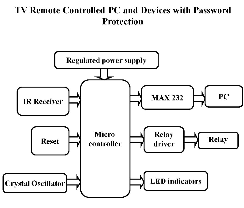
This system consists of an IR receiver that receives the Infrared signals from the TV remote. These signals are fed as input to Microcontroller which processes them and the commands specific to PC operation are sent to the application running inside the computer. The communication between the microcontroller and PC is done by the use of Serial RS232 communication. By using this we can operate any software in computer system like windows media player, browser and etc… To achieve this task, the Microcontroller is programmed with intelligent software written using Embedded C language.

The objectives of the project include: 

  1. Wireless PC control.
  2. Control electrical appliances with TV remote.
  3. Secure way of PC control.
  4. Password enabled control.

This project focuses on the following advancements: 

  1. IR technology.
  2. Mouse control using software.
  3. Conversion of AC supply to DC supply.
  4. Microcontroller and serial port interface.
  5. Embedded C programming.
  6. PCB design.
  7. High voltage devices operation using microcontroller.

The major building blocks of this project are: 

  1. Regulated Power Supply.
  2. IR Receiver.
  3. Micro Controller
  4. Crystal oscillator.
  5. Reset.
  6. MAX 232.
  7. LED Indicators
  8. Electromagnetic Relay with driver. 

Software’s used: 

  1. PIC-C compiler for Embedded C programming.
  2. PIC kit 2 programmer for dumping code into Micro controller.
  3.  Express SCH for Circuit design.
  4. Proteus for hardware simulation.
  5. PC with application 

Regulated Power Supply:

 TV Remote Controlled PC and Devices Regulated Power Supply

Block diagram:


TV Remote Controlled PC and Devices with Block Diagram

Automatic Room Lamp Abstract

Automatic Room Lamp

DESCRIPTION :

First, let us understand why to use Automatic room Lamp? Now-a-days we are going through lots of advertisments of saving electric energy. With the help of Automatic room Lamp we can save and reuse energy. Find the simple block diagram of Automatic room Lamp.

BLOCK DIAGRAM of Lamp

The above block diagram of Automatic room Lamp used to disables the room lamp at day time and enables at night night time. Light Dependant resister(LDR) is the key element of Automatic room Lamp.

Operation:

We need to fix LDR Circuit near to the window/door of home where it can receive maximum sunlight.At day time if we open the door, the resistance of LDR Circuit reduces and leads the transister to remain in cut-off state. So the relay doesnot energize enough,and lamp remains off.
At night time, the resistance of LDR Circuit becomes high and its makes the transistor from cut off state to conducting state. The relay becomes energize and makes lamp to switch on.

We need power supply too operate the following operation.


BLOCK DIAGRAM OF Power Supply

This is block diagram of basic power supply circuit. Transformer is used to step up or step down the input voltage. The bridge circuit is used to convert the alernating current to a pulsating direct current. Since pulsating dc is not desirable, we used filter to convert it to more desirable dc. Regulator is used to maaintain the output of the power supply at a constant level.

Benefits :

Operated only at +5V(d.c)

No use of man power

Used in:

  • Houses
  • Educational Institutions
  • Medical halls
  • Shopping Malls

Recycling Technology Innovation Paper Presentation Seminar Topic

Introduction to Recycling Technology Innovation:

When we feel a certain thing of no use we throw it has a waste. The natural wastes can be dumped in the soil and they get decomposed after some years and they do not pollute the soil or the environment. Here We have implemented Recycling Technology Innovation for reducing electronic wastage’s in present business world.

Now a day the usage of electronic devices has increased a lot and do not have a long life so they are thrown off as a waste and they do not get decomposes in the soil and due to the silicon and other chemicals present in these devices they pollute the environment to a larger extent. The only way to reduce this is to recycle them. In this paper we will the recycle methods on electronic wastes.

Recycling Technology Innovation

Measurements to reduce and Recycling e wastes:

The companies should manufacture the devices with a recyclable material and the usage of silicon should be reduced and an alternative should be found for that. Recycling industries should be encouraged so that the waste material can be reduced and the pollution can be under control.

The usage of ferromagnetic materials and phosphorous and chemical material should be completely controlled because they form poisonous gases when they are burnt and spoils the soil when buried in soil.

Recyclable plastic should be used in the electronic devices so that the wastage can decrease a lot and the companies a reuse the same material which greatly cut downs their manufacturing costs.

Waste Management & Recycling Products Screen Shot:

Waste Management & Recycling Products

Future Recycling Technology App Development:

The electronic wastage should be reduced otherwise it becomes a serious threat for the nature and they cannot be decomposed. The government should take necessary actions and the people should be made aware regarding the effects caused by electronic wastes.

Download Recycling Technology Innovation Engineering Technical White Paper Presentation. Also See all Final ECE Seminar Reports and Project Paper Presentations.

GSM Based Home Security System Project B.tech ECE Idea

Project Title:

GSM Based Home Security System Project

Introduction to GSM Based Home Security System Project:

When we talk about the security the one thing come in mind that whether our home is secure or not. It is must to secure our home first then look at other things. Our home has always important documents, money and other precious things, that need to be protected from the intruders or thieves.  We also need to protect the home from fire and gas leak as they can also destroy our home.  We can use security device at our home that will warn us from any harm by alarm or sending SMS to cell. We can use 8051 micro controller or 89s52.

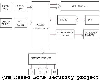
GSM Based Home Security System Project Block Diagram:

GSM Based Home Security System Project B.tech ECE Idea

They are low power chips. They are high performance chips with 8 bit and they is flash memory for storing data.This flash memory allows them reprogram when required. Flash are made up of monolithic chips as they are highly flexible and loss cost. They consist of 32 I/O lines, timers, pointers, oscillators, and clocks etc.

For this microprocessor we use the software called Kiel u- version. This provides tools for the development of the software of the 8051. With the help of this we can generate embedded applications. They use the protocol command named as AT command. They receive the message comes from the phone, then decode the SMS, authenticate the number. Then use their ports to control the specific appliances and after the operation send the feedback to the users for the confirmation.AT command sets are used for the GSM service to connect the device with the mobile phones.

Functions: they have internal RAM and ROM.  Input output ports for programming, timers and counters, 8 bit status words. They contain two 16 bit timers with 4 banks of registers. The RAM used has the memory of 128 bytes. 80 bits are assigned for the general purpose of data memory.