Control Of Reduced Rating Dynamic Voltage Restorer with a Battery Energy Storage System

Description : This Control Of Reduced Rating Dynamic Voltage Restorer with a Battery Energy Storage System project deals with the Dynamic Voltage Restorer (DVR) using reduced rating of voltage source Converter. Voltage sag is crucial power quality problem faced by the utility industry which has resulted in increased attention.

The DVR is a series power quality conditioning device used to eliminate the voltage disturbance. The DVR compensates the voltage disturbance by injecting the voltage of suitable magnitude and phase in series with the line.

DVR is transmission line using the actual line model. This EEE Control Of Reduced Rating DVR with a Battery Energy Storage System project describes the problem of voltage sag and swells and its severe impact on nonlinear loads or sensitive loads.

The DVR has becomes popular as a cost effective solutions. For the protection of sensitive loads from voltage sag and swell.

Solar Inverter using Super Capacitor

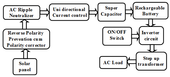
The project aims at developing a solar inverter, which helps farmers to control devices like irrigation water pump, fencing etc. Solar energy is used to power up the battery. The system has a provision for ON/OFF the solar battery charging according to farmers wish.

The project makes use of a solar plate. The solar energy obtained is stored to a battery. This AC is fed to loads like water pump, devices. The system also uses super capacitor to increase the battery life.

Future Scope: This project can be extended in a way such that the output from the solar plate is increased. This can be done by increasing the dimensions of the solar plate.

Conclusion: The project concludes a design of “Solar based inverter” such that the inverter was designed and from solar plate generates solar energy and utilizing this energy for load.

The objectives of the project:

1. Storing solar energy.
2. Design of inverter.
3. ON/ OFF control for loads.

The project focuses on the following areas:

1. Pulse generation techniques.
2. Solar cell working principle.
3. MOSFET working principle.

The major building blocks of this project are:

1. Solar panel.
2. Pulse generator.
3. MOSFET.
4. Step up transformer.
5. ON/ OFF switch.
6. Super capacitor
7. Rechargeable battery

Block Diagram:

Automatic Solar Panel

In our project Automatic Solar Panel we implemented an automatic sun tracking system by utilizing the services of light dependent resistor, the LDR’s position is monitored by the micro controller based on this the angular movements of the DC motor is controlled. It is an intelligent solar power generation system because it generates the energy by itself it doesn’t require any manual operation.

Renewable energy resources are rapidly gaining importance in the field of electrical power generation. We know that solar energy is the most available and popular renewable energy resource, so we need to utilize the solar energy so we implemented a system which tracks the solar energy in its semi circular cycle.

Video link to view circuit diagram, block diagram

http://www.youtube.com/watch?v=QqktCHoWGPg&feature=youtu.be

Proposed system:

The Automatic Solar Panel system is an closed loop system designed to align the solar panel toward the sun rays. Here in this project the angular position of the solar panel is controlled by the dc motor which is interfaced with the control system circuitry having micro controller setup. The LDR detects the maximum intensity of the sun light and send the signals to the micro controller then the micro controller manipulates the dc motor for rotating the solar panel towards the maximum intensity regions.

Light Depended Resistor:

The name itself depicts that the resistance value is dependent on the intensity of the light i.e. such that the resistance is low whenever the sun light intensity is high and vice versa.

Fabrication:

The PCB fabrication is done to provide the electrical inter connections to various components in the circuit. This process involves drilling, cutting, cleaning, wiring, soldering and testing.

 Download Automatic Solar Panel Project Report

Observation:

We observed the working of Automatic Solar Panel project practically here we placed a black cloth on the four LDR’s to provide uniform light intensity then we removed the cloth on LDR1 panel moved forward, and we removed the LDR2 the panel moved backward like that we conducted serial verification and we found that the system is successful in detecting the variations in the sun light.

Power Generation Using Speed Breaker

In this project Power Generation Using Speed Breaker is designed with intent to make every speed breaker as a source of power. In order to meet the increasing demand of electricity we need to utilize every means of energy waste for the production of electricity.

Speed breaker generator mechanisms:

The basic principle involved in Power Generation Using Speed Breaker system is conversion of mechanical energy into electrical energy. The vehicle weight is taken as potential energy input for the generation of electricity. The three mechanisms are Crank-shaft mechanism,Roller mechanism and Rack- Pinion mechanism and the phenomenons and abilities with their advantages are clearly discussed in the coming sections. Rack- Pinion mechanism find to more beneficial than the other two by providing greater efficiency, with less gear loss.

Youtube video link to view presentation on same topic

http://www.youtube.com/watch?v=_HEz84lRcb0&feature=youtu.be

With a steady flow of traffic over this electro-kinetic road ramp system will generate electricity and the generated can be stored in batteries to power all the street lights, traffic lights.

Download Power Generation Using Speed Breaker Project Report

Experimental verification:

As far considering the practical implementation results this system is low cost equipment with less maintenance, and highly efficient, reliable in densely populated areas. In case we design the speed bumps for heavier vehicles which can inject high torques on the speed bumps their by we can extend the range of electricity production.

Download full project report, project documentation and paper presentation PPT from below download links.

Control Techniques To Amend The Performance Of Dc-Dc Converters Project

Control Techniques To Amend The Performance Of Dc-Dc Converters Project Conclusion:

We know that a DC-DC Converters has various applications like in dc drives, subway cars, trolley trucks, battery driven vehicle etc. DC-DC Converters are used to obtain a regulated power supply from an unregulated power supply. But due to controlling of switch and some other factors the performance of these converters is not good there are some drawbacks as bandwidth limitation, high settling time, discontinuous outputs, poor dynamic performance, bad transient performance, and Existence of right-half-plane-zero (RHP) in CCM Operation of boost, flyback and cuk Converter etc. so from many decades there are various effort is done to improve the performance of DC-DC Converters.

Performance can be improved by proper selection of values of L, RL, C, RC and the duty ratio for switch. Various techniques are used to control the switch as pulse width modulation, pulse skipping modulation, pulse frequency modulation, Current control techniques, Voltage control techniques, current injected control, feedback compensation, capacitive energy transfer principle, New Energy transfer principle (coupling of inductor), Dual mode control, sliding mode control, Tri-state Boost Converter etc. 

In the literature it has shown that in general, voltage across the capacitor (output voltage) and current through the inductor (inductor current) are two variables usually considered in the closed feedback loop of a dc-dc converter. However, because of the regulatory purpose, the former one is indispensable irrespective of the control schemes, while the latter one is considered for further improving the dynamic performance.

The voltage mode control (VMC) uses the output voltage as the only feedback variable; while in addition, the current mode control (CMC) uses the inductor current. In recent past, apart from these, other variables, like current through the load (load current), derivative of the output voltage etc., have been considered. Nevertheless, the objects (performance and efficiency) in all the cases are more or less the same.

Currently a current controlled Tri-state boost converter are used to improve the performance of boost converter and it reduces the settling time of reference voltage transient and load transient upto 0.45ms and 0.09ms respectively which was for voltage mode control 7ms and 3ms respectively. It also increases the band of current loop upto 28 kHz which was 5 kHz for current mode control. Hence this technique is better than any other technique.

Elimination of RHP Zero for the Improvement of Performance of Boost Converter

Introduction to  Elimination of RHP Zero for the Improvement of Performance of Boost Converter Project:

We first revisit the small signal modeling of a CCM boost converter, and confirm the presence of a RHP zero in its control-to-output transfer function. We then explain the operation of a tri-state boost converter. We carry out the formulation of the open-loop small signal model of the same. We discuss the choice of control variables for possible elimination of the RHP zero. Finally, we propose a current control scheme for the tri-state boost converter circuit configuration.

The proposed scheme (a) completely eliminates the RHP zero, (b) Gives a superior dynamic performance in comparison with the schemes proposed earlier, (c) Achieves a step up ratio greater than 3 with stable periodic behavior without the use of a compensation ramp. We discuss the need of feed-forward control in enlarging the operating region, improving dynamic performance and efficiency. We carry out fast scale stability analysis and slow scale transient analysis. We validate the theoretically predicted behavior experimentally. Finally, we briefly discuss about the elimination of the RHP zero in a buck-boost converter. 

A Conventional Boost Converter 

The schematic of a conventional boost converter is shown in Fig. 1. For a dc-dc boost converter, if the MOSFET on-time (related to the duty ratio) is increased, the capacitor discharge time increases which implies a reduction in the output voltage. The output voltage continues to dip further until the inductor gets sufficient energy to build it up again, which results in an initial undershoot of the output voltage.

Future Plan 

  • We improve the performance of boost converter by the improving of this technology by designing the values of parameter k1, k2, k3, kp, & ki. 
  • Use other techniques for tri-state boost converter control like the constant charging interval and dual mode control, recently proposed in the literature. 
  • Implement this topology for Buck- Boost Converter.