Cloud and IoT Based Health Monitoring System Project

Objective

Our system is useful for monitoring the health system of every person by easily attaching the device and recording it.

We can analyze patients’ conditions through their past data, IoT sensors are being utilized to consistently record and monitor health conditions and transmit alerts in the event that any uncommon signs are found.

If there should be an occurrence of a minor issue, the IoT application additionally has the arrangement to recommend a medicine to the patients.

Introduction

This project is the solution to be able to make use of IoT sensors and actuators to be able to detect issues with subscribed patients remotely to be to monitor health, emergencies, statistics, etc, This makes use of Cloud, Machine learning, IoT platforms, and devices.

The results can be recorded using Arduino.

The doctors can see those results on an application. The system will also generate an alert notification which will be sent to the doctor.

Literature Survey

  • Smart Health Monitoring Systems: An Overview of Design and Modeling
  • Cloud-Based Privacy-Preserving Remote Monitoring and Surveillance
  • A Review of Machine Learning and IoT
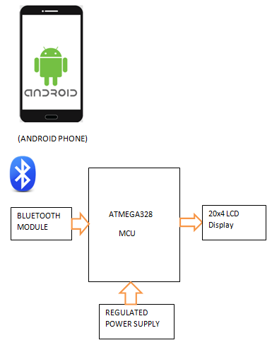
Architecture Design

The Flow diagram for Cloud and IoT based Emergency response system follows Sensing, Processing Unit, Cloud Server and Analysis.

Hardware  and Software Requirements:
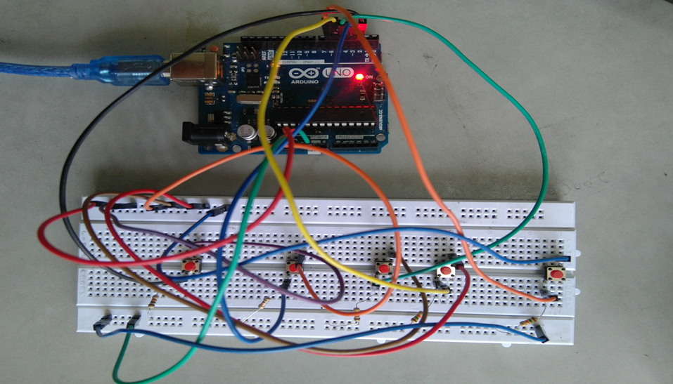
Arduino: 

IoT Sensors: The main purpose of sensors is to collect data from the patient’s body and from the surrounding environment. 

Cloud: These cloud computing platforms are used to store the data and perform some analysis on the data which is stored on the cloud.

Product Perspective

User Classes and Characteristics

The main objective is to design this System with two-way communication i.e. not only the patient’s data will be sent to the doctor through SMS and email in emergencies, but also the doctor can send required suggestions to the patient or guardians through SMS or Call or Emails.

The user base for this application involves patients and old age people.

Assumptions and Dependencies

Appreciable accuracy in IoT sensors to fetch accurate data. 

Reliable internet connections. 

User Interfaces

Front-end:

  • Web application
  • IoT sensors

Back-End:

  • Open Source IoT platform

Functional requirements

  • Sensors frequently detect data from patients.
  • Collected information is updated in the cloud.

Performance Requirement

The data analysis and communication (response) between the user device and subscribed user must be quick.

Conclusion

The primary purpose of a  health monitoring system is to allow people to lead independent and active lives in their familiar home environment while ensuring continuous, non-invasive, non-intrusive, and seamless surveillance of their health and physical well-being. Continuous monitoring of health status can provide comprehensive information about individuals’ health status over a period of time.

Download the complete project Code & paper Presentation of Cloud and IoT Based Health Monitoring System Project.


Implementation of E-voting Machine Project using Python and Arduino

INTRODUCTION

Our E-voting Machine project is very useful, This Project was implemented using Python and Arduino. The user is no longer required to check his register in search of records, after the voting procedure gets over, the admin will be able to calculate the total number of votes in just one click since the entire work is done using computers. The user just needs to enter his/her unique voter ID.

In today’s world, no one likes to manually analyze the result after the voting procedure gets over because the process is time-consuming and of which results get usually delayed. Everyone wants his/her work to be done by computer automatically and displaying the result for further manipulations. So this E-voting Machine project is about providing convenience regarding voting.

OBJECTIVE

  • Our objective for the E-voting Machine project is to make a user-friendly Electronic Voting Machine that makes the current voting process faster, easier, and error-free.
  • We have used Arduino in our project for the implementation of push buttons and Python as a programming language.

PROBLEM STATEMENT 

The problem statement was to design a module:

  • Which is a user-friendly E-voting Machine
  • Which will restrict the user from accessing other users’ data.
  • Which will ease the calculations and storage of data.
  • Which will help the jury to declare the result without any biasing.

FUNCTIONS TO BE PROVIDED:

The E-voting Machine system will be user-friendly and completely secured so that the users shall have no problem using all options.

  • The system will be efficient and fast in response.
  • The system will be customized according to needs.

FOR e-VOTING SYSTEM

  • (Check
  • Store
  • )

SYSTEM REQUIREMENTS

  • Programming Language Used: Python, C
  • Hardware Used: Arduino UNO
  • Components Used: Push buttons, Connecting Wires, Resistances(100k ohm), Breadboard
  • Software Used: Anaconda 2.7.x, Python 2.7.x, Arduino IDE
  • Modules Used: Serial, SQLite, Tkinter, tkMessageBox

WORKING

  • The user has to enter his/her ID in the system.
  • After verifying the user ID, the system will show a message that whether a user is eligible to vote or not after checking his/her details stored in the system.
  • A message will be displayed accordingly. The user will then have to press the button against which the name of the candidate is written and whom he/she wants to vote.
  • The votes hence are stored in the database and the results will be announced accordingly.

FUTURE SCOPE OF THE PROJECT

My project “e-VOTING SYSTEM” will be a great help in conducting voting at various organizations. So the modifications that can be done in our project is to add one major change which can be done in this project is to add the data of the voters. This will result in the total identification of the voter.

CONCLUSION

From this E-voting Machine project, we can conclude that this program is very useful in conducting the voting procedures smoothly. It provides easy methods to analyze the voting result. It helps in conducting faster, more secure, and more efficient voting. The program can be used per the norms of the voting requirements.

Download the complete project code, report, and PPT on E-voting Machine using Python and Arduino.

Two Wheeled Self Balancing Robot Minor Project Synopsis

Introduction

The basic working principle behind a self-balancing robot is an inverted pendulum concept model in control theory, according to which the robot drives the wheels in the direction in which it tilts. Examples of the inverted pendulum in certain real applications include rockets like MAXUS, Segway the personnel transporter, and a self-balancing vehicle.

It has great advantages like small size, flexibility, and low cost because of these advantages, it can be used in various applications in the field of control engineering. The inherent complexity associated with the control of this platform finds its application in the design and development of control systems for automobiles, spacecraft, and transportation facilities including military transport.

The developed hardware is used to develop an object-carrying vehicle that can be used to reduce human efforts in working places, offices, and household applications.

This is a cost-effective solution using the PID algorithm for these two-wheeled vehicles.

Rationale

Because of the previously stated advantages that come with a two-wheeled self-balancing design, a number of consumer products have recently gone mainstream that utilize a similar idea for purpose of convenient human transportation, i.e. – Hover-boards, Segway, and self-balancing two-wheelers. Our goal with this project was to demonstrate the balancing mechanism used in these products in a compact, cost-effective prototype of a self-balancing robot.

Objectives

1. To balance the whole body on two wheels automatically by designing the best possible structure for the body and obtaining the filtered values from the gyro and accelerometer sensor i.e. – mpu6050.
2. To use inbuilt Wi-Fi or Bluetooth capabilities of ESP32 microcontroller to communicate with the robot in order to de- liver the commands to follow.
3. To fine-tune custom PID values for the robot to ensure its smooth maneuverability.
4. To generate the ability to balance and maneuver with objects placed on its head

Feasibility Study

1) Feasibility of the project

The project is intended to explain the design along with the construction and control mechanism of a two-wheel self-balancing robot. To deal with the problem of sudden horizontal movements and gyro drifts in sensors, a complementary filter is implemented[1]. PID (proportional integral derivative), is the feedback mechanism used for this project.

2) Need of the project –

1. Its ability to turn on the spot and sustainable architecture increases its applications in industries.
2. It is essential for the robot to not only balance but also maintain its position, withstanding external forces or unexpected disturbances if any

3. Active research on two-wheeled robots has been widely increased since the early versions of the studies on self-balancing robots by JOE and n-BOT.

3) Significance of the project –

These robots can be used for

1. Smart gardening purposes.
2. Autonomous trolleys in malls, hospitals, and airports.
3. An intelligent robot for various industrial-military purposes.

4. Currently popularized as “Segways,” these machines are mostly used for travel and tourism purposes and by private security services. It has been put to use by a range of private and military organizations since its invention.

Methodology/ Planning of work

The main objectives of a system for Online voting system are:

1. The objective of the Online voting system is to help the organization in automating the whole manual processing of the existing system.
2. Test the working and compatibility of all electronic components (mpu6050 and motors and its driver) with ESP32 separately and ensure the proper working of each component. a rudimentary prototype using all components with temporary wiring on the breadboard in order to test the integrated working of the components with each other (without tuning PID values).
3. Fabricate the basic frame of the robot using acrylic sheets, spacers, screws, and angle brackets.
4. Mount all electronic components onto the frame.
5. Make wired connections according to the planned circuit.
6. Upload code to ESP32 from Arduino IDE.
7. Update PID values.
8. Test the performance, balance, and maneuverability of the machine, if not satisfied with its performance, go to the 7th step in order to fine-tune PID values else the required development of the robot is completed.

Facilities required for proposed work

Software Requirements:-

1. Arduino IDE

Hardware Requirements:-

1. Arduino IDE
2. ESP32 microcontroller – 1
3. MPU6050 sensor – 1
4. Bo geared motors – 2
5. L298N Motor driver -1
6. 3.7v 18650 Li-ion battery – 2
7. Assorted Jumper Wires
8. 3mm Acrylic Sheet
9. 65mm Nylon Tyres – 2
10. Angle Brackets – 2, Spacers and Screws

Design and Implement a Healthcare Monitoring and Management System IoT Project

Nowadays Internet of Things is bringing a revolution in the infrastructure of technologies. The IoT-based health monitoring system is essentially a patient monitoring system in which he can be supervised 24*7. Remote Patient Monitoring arrangement enables observation of patients outside of customary clinical settings (e.g. at home), which expands access to human services thus bringing down costs. Healthcare is given extreme importance by each country with the advent of the novel coronavirus.

Recently there has been a spike in the use of smartphones and along with that, wearable sensor remote health monitoring has evolved quickly. IoT not only helps in preventing the spread of disease but also in getting a proper diagnosis, even if the doctor is present at a remote distance By facilitating effortless interaction among various modules, IoT has enabled us to implement various complex systems such as smart home appliances, smart traffic control systems, etc.

PROPOSED SYSTEM:

The main objective of this Healthcare Monitoring and Management System is to develop, design, and implement a smart patient healthcare monitoring system. The sensors used here are embedded in the body of the patient to sense the parameters like the heartbeat and temperature. These sensors are connected to a master unit, which calculates all of their values. These values are then transmitted by leveraging IoT cloud technology, to the base. From the base station, these can be easily accessed by the doctor present at some other location. Thus based on the temperature and heartbeat values, the doctor can decide the state of the patient and appropriate measures can be taken.

OBJECTIVE:

Monitor patient parameters remotely to increase the efficacy of healthcare management systems

IDEATION:

We need to monitor the patient parameters from remote distances using various sensors. The data given out by the sensors are then sent over to the cloud for further access via a Wi-Fi module (inbuilt or externally connected). This is being done to reduce the critical time of testing patient parameters before any major operation.

Here we are measuring the temperature and pulse parameters of a patient remotely.

Components required:-

MLX 90614 Temperature
MAX 30102 Pulse Rate
Jumper wires.
Nodemcu ESP8266 board

The Gantt Chart is shown below:-

smart patient healthcare monitoring system

Summary:-

 Health care is given extreme importance nowadays by each country with the advent of the novel coronavirus. Thus in this regard, an IoT-controlled healthcare monitoring system is most probably the best solution for such an epidemic. Internet of Things (IoT) is the new revolution of the internet which is a growing research field, especially in health-related services.

“Healthcare Monitoring and Management System” is the project where we have mainly focused on two objectives first one was a smart health monitoring system, to collect the health history of patients with a unique ID and store it in a database so that doctors need not spend much of their time in search of the report and give analysis right from the dashboard. Any health care that is being done will be updated and reflected in the dashboard itself. And the other one is the Wearable-Sensor-Based Fall Detection System for aged people, to monitor their movements of them, recognize a fall from normal daily activities by using sensors, and automatically send a request or an alert for help to the caregivers so that they can pick up the patient.

However, there are a few shortcomings to this too. Basic knowledge of the operation is to be learned by the caregivers. Also, both the caregiver and the wearer should know how to protect the sensors from water damage or any physical damage. 

  • Planning and project management 

S.No.

Activity

Starting Week

Number of Weeks

1.

Literature Review

1st week of January

 2

2.

 Project Finalization

3rd week of January

 1

3.

Required software setup

4th week of January

 1

4.

Gathering of Hardware & Formation of codes

1st week of February

1

5.

Hardware assembly calibration

2nd week of February

 1

6.

Code Integration & Debugging

3rd week of February

 2

7.

Inclusion of IoT and Blynk

1st week of March

 1

8.

Finalization & modification of Website and mobile application

1st week of March

 1

9.

 Preparation of project report

2nd-3rd week of March

 2

10.

Preparation of Project presentation

4th week of March

1

Development of IoT Project on Intelligent Cargo Management System

The integration of such sensors in cargo has paved the way for intelligent transportation. These integrated systems are competent in delivering reliable details about the quality of the goods during their depository time.

To reach this goal, we use a variety of sensors suited for monitoring the safety of food products and goods by recording the transition of parameters like temperature, humidity, and air quality, fire detection.

This information is transmitted wirelessly to the IBM cloud providing an interface where the authorized person can observe the product quality over time and also receives alert messages in case of bad air quality and abnormal conditions.

Block Diagram:

Block Diagram of Intelligent Cargo Management System

An Intelligent Cargo Management System app is designed for selecting the type of goods to be stored in the truck, for door automation, and for retrieving the values from the sensor.

Initially, the authorized person of the truck has to select the type of goods stored in the truck through the Cargo Management System app. Based on the selection, the temperature and humidity values at which the goods are supposed to be stored will be known. Using the DHT11 sensor, the actual temperature and humidity inside the truck can be known.

The temperature and humidity values can be obtained from the app. By comparing these values, a message will be sent to the authorized person asking him/her to turn on the AC or the heater in any abnormal conditions.

The air quality inside the truck is constantly monitored using MQ135 sensor. If the quality of the air inside the truck is bad, a message is sent to the authorized person regarding the same.

Through this goods can be maintained in constant conditions and their quality is maintained for a longer time. A fire sensor is also deployed in the truck to detect fire. If the fire is detected, the buzzer rings alerting the driver of the fire. The door of the truck is automated using a servo motor.

The authorized person of the truck can open or close the door of the truck using the Cargo Management System app.

Home Safety and Security System Using IoT Project

The main objective of the Home Safety and Security System Using IoT project is to implement a home safety and security system with the following features:

  • Monitoring and detection of leaks in LPG gas
  • Unauthorized opening of door/window

Hardware Requirements:

The hardware for the project consists of:

GISMO-V board with:

  • ESP32 dual-core 32-bit processor with Wi-Fi and BLE
  • MQ6 sensor module
  • Magnetic switch assembly
  • 0.96” OLED display with 128×64 resolution

Cloud Platform:

In this project, we are going to use Google’s firebase as a cloud database. It is a No-SQL database in which data is stored as Key-Value pairs.

To access the database the following credentials are required

  • Host URL
  • Database authentication key

These credentials are put into the ESP32 firmware to access the Google Firebase.
The keys used to store the parameter values in the project are:

  • IOTLAB/HSSS/Gas_Leak
  • IOTLAB/ HSSS/Window_Open

Mobile App:

  • The Modular rapid mobile app development utility is used for the development of the mobile app. The utility has two modes, a Developer mode, and a Blocks mode. Different functional blocks are available in developer mode, they are – User Interface, Sensors, Connectivity, Firebase, and so on.
  • In the Blocks mode, a timer with timing set to two seconds will fetch the LPG gas concentration and magnetic switch status values from the Firebase database and fill it in the appropriate place in the UI.
  • To access the Firebase dataset its credentials will be placed in the Firebase component of the Modular app.

Mobile App development of Home Safety and Security System Using IoT Project

Results and Conclusions:

With the help of the MQ6 sensor and magnetic switch, we monitored the leakage in LPG gas and also the window/door open status.
We can get notified with the help of the mobile app.

Download the complete Home Safety and Security System Using IoT Project code, report, ppt, design document, and SRS.

A Smart & Secure Helmet IoT Project

Abstract

This Smart & Secure Helmet IoT Project is aimed at using the concept of the Internet of Things (IoT) and chemistry with the rider’s helmet to provide extensive safety, guidance, and health care features. The following features are planned to be implemented in a phase-wise manner in the project :

1. Internet of Things(IoT) based traffic emergency system

2. Internet of Things(IoT) based traffic guidance system

3. Extensive protection from sunstrokes

4. GPS tracking

All these facilities are to be implemented on the helmet with maximum cost efficiency to make the final product within the reach of the Indian common man.

Goal

The goal of this project is :

  • To provide advanced traffic safety mechanisms through IoT to the people at affordable costs.
  • To provide IoT-based traffic guidance system to the people – first target: Tier-1 cities in India
  • To provide extensive protection from sun strokes, especially during the hot summer season in India
  • To make this project an innovative platform for many other applications like Easy GPS tracking, Health sensor, etc.

Motivation

There has been a multiple-fold rise in the number of road accidents in recent days and many times, emergency services have faced difficulty in a timely response to the situation.

In large cities, sometimes the emergency services find it difficult to locate the spot of the accident based on a phone call.

Companies(logistics, customer service) face difficulties in tracking the vehicles of their employees

Even with the heavy risk of not wearing a helmet, People do it as they find it inconvenient to wear a helmet in hot humid sub-Continent conditions. Our new chemical system compartment in the helmet solves it.

All these situations prompted us to look into the possibility of IoT coming up helping people in these cases and we found out that in the initial phases of our project, we can use the helmets used by people while driving. Later the same technology can be used on other vehicles to provide an all-around extensive safety mechanism.

Class Diagram:

ADVANTAGES

The helmet will be mounted with appropriate sensors at appropriate positions on the helmet. They are calibrated to sense high impact due to an accident or crash.

Once they detect the designated input, the rider’s location is immediately sent to a cloud of hospitals, and the nearest hospital is notified about that so that the ambulance can reach the spot immediately.

1. Immediate response to any accident by the emergency services since all of them become a part of the network (of things).

2. The location of the accident is too updated to the emergency services so that finding the location won’t be much trouble.

3. Details of the personnel are also updated to the emergency service center so that formalities of paperwork may be completed beforehand.

4. Continues tracking of employees for Companies like logistics, customer service, etc.

5. Proper Traffic Guidance using Google Services.

6. Humidity reduction inside Helmet.

7. Many inbuilt Bluetooth facilities like automatic call acceptance (while driving) etc.

Conclave on the Internet of Things provided us with exposure to the applications of the concept of the Internet of Things (IoT) and several other creative approaches that solve day-to-day problems by invoking the interconnection and sharing between the day-to-day products.

Apart from the conclave, we would like to appreciate the suggestions and help from the faculties which proved to be a priceless booster to our project.

We are a team dedicated to the research and development of creative solutions to day-to-day problems. We aim at creating smart, simple, innovative ad cost-effective solutions which could be affordable for the common man of India.

Future Work

PROTOTYPE-II: To implement a traffic guidance system using Google services.

PROTOTYPE-III: To implement a fully integrated traffic safety and guidance system

School Bag Security Device Microcontroller Project

Bag Security is a device developed in partial fulfillment of the course of Microcontroller and its applications that gives an indication to the owner whenever the Bag zip is opened when it is carrying. This School Bag Security project also displays the number of books in the bag which is useful for children below 10 years to verify whether they are carrying the same number of books they bought from home or not.

CIRCUIT DIAGRAM:

OUTPUTS IN BOTH PROTEUS AND HARDWARE:
CASE 1: INCREMENT OF BOOKS:

EXPLANATION:

For increment first, the IR sensor1 will be detected and then IR sensor2 will be detected then only the book will be increment. IR sensor1 should be placed near the bag zip and IR sensor2 should be placed below the IR sensor1.

This shows the connections for our project left side two switches are IR sensors and the left side two switches are one switch and another IR sensor

CASE 2: DECREMENT OF BOOKS:

EXPLANATION:

For Decrement first, the IR sensor2 will be detected and then IR sensor1 will be detected then only the book will be decrement. IR sensor1 should be placed near the bag zip and IR sensor2 should be placed below the IR sensor1.

CASE3: WHEN ZIP IS OPEN:

EXPLANATION for case3:

The buzzer should ring only when we are carrying the bag and also when the zip is opened the truth table explains that. So, we kept the switch on the bag Zip and the Ir sensor below the zip inside the bag. When the switch is on and also the Ir sensor detects the light then the buzzer or LED will be ON.

CONCLUSION:

We have designed a device that will ring the buzzer only when we are carrying the bag and also when the zip is opened. And also, we have included an LCD which displays the number of books in the Bag.

COMPONENTS USED:

  • Microprocessor development board
  • AT89C51
  • IR SENSOR
  • LCD

Download School Bag Security Project

This project was developed with an 8051 Microcontroller.

Accident Avoidance Using IBS and AOCS Major Project

Accidents are increasing at a higher pace and are most common if driving is inadequate. Driver drowsiness is considered an important factor in vehicle accidents, Over Speed can also be considered as another important factor for vehicle accidents.

The main objective of this project is to develop a system for automatic speed control and accident avoidance using eye blink and ultrasonic sensors to keep vehicle secure.

It includes an intelligent braking system in which, whenever any obstacle comes in front of a running vehicle the ultrasonic sensor detects the obstacle at a distance of 4m away from it and sends a signal to embedded board or microcontroller.

And if the driver is drowsy or about to sleep, then the eye blink sensor detects the eye blink and if eyes are closed for more than 30 seconds, the vehicle stops automatically.

Apart from these, the safety of the vehicle can also be ensured by introducing A.O.C.S (Automatic Over Speed Control System). It basically controls the speed of the vehicle by continuously checking it through sensors which sends the signal to the microcontroller.

Whenever the speed is increased above the predefined critical speed, the microcontroller through its logical circuits sends the signals to the actuators via its output pins. The actuators apply necessary force on the brakes and reduce the speed to its safe value.

The sensor used in this system is an optical type infrared sensor and the actuators are stepper motors to which the output of the microcontroller is connected.

Android Based Voice Controlled Notice Board

We are using voice recognition Android App for updating message on 20×4 LCD with the help of Bluetooth module HC-05. The android app converts speech into text using google speech to text conversion.

We are sending text data using mobile phone which is received by Bluetooth module and given to microcontroller. The microcontroller used here is from Arduino UNO(Atmega328) which sends the same message on it.

Software:

• ARDUINO IDE
• EMBEDDED CPP CODE
• Proteus Simulator

Hardware :

1. ATMEGA328 Microcontroller
2. Bluetooth Module
3. 20×4 LCD Display
4. Regulated Power Supply

BLOCK DIAGRAM: