Automatic Video Surveillance System AI & IOT Project

Surveillance is an integral part of security. The main objective of the Video Surveillance system IoT project is to build an effective system that can be used across different domains and technologies. The system is used to Detect Human intervention and breach in personal or commercial property of the user in real-time using AI and IoT.

It helps users to secure their property with the help of advanced artificial intelligence. The resulting system is fast and accurate, thus helping users with more secure surveillance systems.

For the most part, the job entails looking out for something undesirable to happen. The application is to have a system that provides real-time monitoring and alert security when a human is detected in a user’s property in their absence.

OBJECTIVES:

The main objective is to build an effective Video Surveillance System that can be used across different domains and technologies. The system is used to detect people trying to breach security in the personal or commercial property of the user in real time and send a message along with a short video clip to the user. 

PURPOSE OF EXISTING SYSTEM:

Currently, the existing Rocker Bogie Suspension Systems Project or surveillance robot for defense Surveillance systems can keep video recordings of homes, offices, banks, and so on. But that is useful only after an incident or robbery happens. No Real-time Updates are provided when there is a breach in real-time. 

Just imagine, You’re at your home and someone breaks security and stole money or goods from your office or property. Or consider you’re out of town for some days and there is a robbery at your home. So after you come back home or someone identifies it after some time and they will update you about the breach at your place.

You can take any action after a breach has been done, not at the time it is being done. That issue will be resolved in our system with real-time monitoring and updates.

SCOPE OF SYSTEM:

The Video Surveillance System can be implemented in any residential, Industrial, or commercial property. The system recommends detecting any human intervention on the user’s property and sends a notification along with a threshold of a 10-second video clip immediately as soon as it detects humans.

PROBLEM DEFINITION:

This Video Surveillance System project aims to develop an advanced Surveillance system that can keep on monitoring homes, offices, banks, and so on. With the help of this, you can find out if anyone breaches your security in your absence. We have to simply integrate our system into users existing surveillance systems. 

Module specification: 

  1. Raspberry pi
  2. Camera
  3. Server
  4. SNS
  5. S3  

Need Of Modules:

  • Raspberry pi as a Client to send frames to the server.
  • Camera to capture live video streams.
  • Server for processing frames and detecting humans.
  • SNS sends a multimedia message to a user when someone tries to breach security.
  • S3 to store a short video clip of the breach and send it to the user.

Non-Functional requirement.

EFFICIENCY REQUIREMENT :

When AI is taking care of your property then customers can relax and not have to worry about their security.

RELIABILITY REQUIREMENT :

 The system should provide a reliable environment for both the client and the server.

USABILITY REQUIREMENT :

The system is designed for a secure environment and ease of use.

IMPLEMENTATION REQUIREMENT :

Implementation of the system with pi, night vision camera, python, machine learning, and AI.

DELIVERY REQUIREMENT

The whole system is expected to be delivered in four months of time with a weekly evaluation by the project guide.

Limitations of the System:-

False Positives

Due to different light variant conditions and camera resolutions, sometimes the system detects humans as false when there is none but that can be neglected if there is a human and the system doesn’t detect it then there should be a problem.

Limited Processing Power

As we are using a microcontroller to send feeds to the server, it cannot handle multiple feeds at once and will be slower as the device increases.

Download Automatic Video Surveillance Management System Project Python Code, Documentation & report, Paper Presentation PPT

Cloud and IoT Based Health Monitoring System Project

Objective

Our system is useful for monitoring the health system of every person by easily attaching the device and recording it.

We can analyze patients’ conditions through their past data, IoT sensors are being utilized to consistently record and monitor health conditions and transmit alerts in the event that any uncommon signs are found.

If there should be an occurrence of a minor issue, the IoT application additionally has the arrangement to recommend a medicine to the patients.

Introduction

This project is the solution to be able to make use of IoT sensors and actuators to be able to detect issues with subscribed patients remotely to be to monitor health, emergencies, statistics, etc, This makes use of Cloud, Machine learning, IoT platforms, and devices.

The results can be recorded using Arduino.

The doctors can see those results on an application. The system will also generate an alert notification which will be sent to the doctor.

Literature Survey

  • Smart Health Monitoring Systems: An Overview of Design and Modeling
  • Cloud-Based Privacy-Preserving Remote Monitoring and Surveillance
  • A Review of Machine Learning and IoT

Architecture Design

The Flow diagram for Cloud and IoT based Emergency response system follows Sensing, Processing Unit, Cloud Server and Analysis.

Hardware  and Software Requirements:

Arduino: 

IoT Sensors: The main purpose of sensors is to collect data from the patient’s body and from the surrounding environment. 

Cloud: These cloud computing platforms are used to store the data and perform some analysis on the data which is stored on the cloud.

Product Perspective

User Classes and Characteristics

The main objective is to design this System with two-way communication i.e. not only the patient’s data will be sent to the doctor through SMS and email in emergencies, but also the doctor can send required suggestions to the patient or guardians through SMS or Call or Emails.

The user base for this application involves patients and old age people.

Assumptions and Dependencies

Appreciable accuracy in IoT sensors to fetch accurate data. 

Reliable internet connections. 

User Interfaces

Front-end:

  • Web application
  • IoT sensors

Back-End:

  • Open Source IoT platform

Functional requirements

  • Sensors frequently detect data from patients.
  • Collected information is updated in the cloud.

Performance Requirement

The data analysis and communication (response) between the user device and subscribed user must be quick.

Conclusion

The primary purpose of a  health monitoring system is to allow people to lead independent and active lives in their familiar home environment while ensuring continuous, non-invasive, non-intrusive, and seamless surveillance of their health and physical well-being. Continuous monitoring of health status can provide comprehensive information about individuals’ health status over a period of time.

Download the complete project Code & paper Presentation of Cloud and IoT Based Health Monitoring System Project.


Implementation of E-voting Machine Project using Python and Arduino

INTRODUCTION

Our E-voting Machine project is very useful, This Project was implemented using Python and Arduino. The user is no longer required to check his register in search of records, after the voting procedure gets over, the admin will be able to calculate the total number of votes in just one click since the entire work is done using computers. The user just needs to enter his/her unique voter ID.

In today’s world, no one likes to manually analyze the result after the voting procedure gets over because the process is time-consuming and of which results get usually delayed. Everyone wants his/her work to be done by computer automatically and displaying the result for further manipulations. So this E-voting Machine project is about providing convenience regarding voting.

OBJECTIVE

  • Our objective for the E-voting Machine project is to make a user-friendly Electronic Voting Machine that makes the current voting process faster, easier, and error-free.
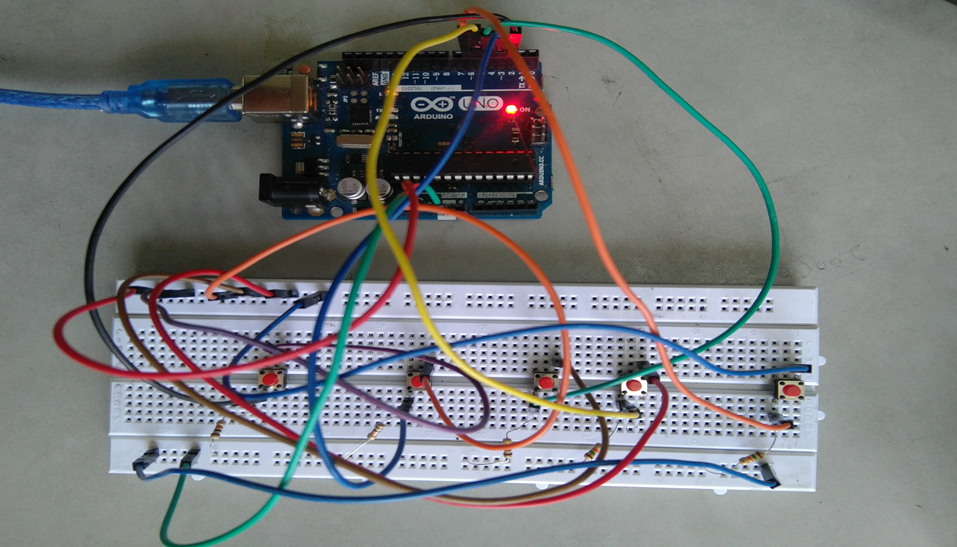
  • We have used Arduino in our project for the implementation of push buttons and Python as a programming language.

PROBLEM STATEMENT 

The problem statement was to design a module:

  • Which is a user-friendly E-voting Machine
  • Which will restrict the user from accessing other users’ data.
  • Which will ease the calculations and storage of data.
  • Which will help the jury to declare the result without any biasing.

FUNCTIONS TO BE PROVIDED:

The E-voting Machine system will be user-friendly and completely secured so that the users shall have no problem using all options.

  • The system will be efficient and fast in response.
  • The system will be customized according to needs.

FOR e-VOTING SYSTEM

  • (Check
  • Store
  • )

SYSTEM REQUIREMENTS

  • Programming Language Used: Python, C
  • Hardware Used: Arduino UNO
  • Components Used: Push buttons, Connecting Wires, Resistances(100k ohm), Breadboard
  • Software Used: Anaconda 2.7.x, Python 2.7.x, Arduino IDE
  • Modules Used: Serial, SQLite, Tkinter, tkMessageBox

WORKING

  • The user has to enter his/her ID in the system.
  • After verifying the user ID, the system will show a message that whether a user is eligible to vote or not after checking his/her details stored in the system.
  • A message will be displayed accordingly. The user will then have to press the button against which the name of the candidate is written and whom he/she wants to vote.
  • The votes hence are stored in the database and the results will be announced accordingly.

FUTURE SCOPE OF THE PROJECT

My project “e-VOTING SYSTEM” will be a great help in conducting voting at various organizations. So the modifications that can be done in our project is to add one major change which can be done in this project is to add the data of the voters. This will result in the total identification of the voter.

CONCLUSION

From this E-voting Machine project, we can conclude that this program is very useful in conducting the voting procedures smoothly. It provides easy methods to analyze the voting result. It helps in conducting faster, more secure, and more efficient voting. The program can be used per the norms of the voting requirements.

Download the complete project code, report, and PPT on E-voting Machine using Python and Arduino.

GPS-based Child Tracker with Emergency Text Alerts IoT Project

The hectic life of parents makes it very difficult to personally look after the kids. To overcome the problem of personal monitoring of children, we have come up with the idea of a GPS-based tracker with text alerts when the child is not present in the specified region.

Problem Statement:

To solve the problem of difficulty in keeping a check on children while they are playing in open areas while letting the children have their freedom to play from constantly being mocked by parents and to monitor the whereabouts of children by working parents. There is a similar project on Women Security System that can be seen here

Project Working Process:

Hardware Components

  • Arduino UNO
  • GPS Module
  • GSM/GPRS Module 

Software’s Used

  • Arduino IDE
  • Android (MIT App Inventor)

In this context, the solution we propose is a GPS-based Child Tracker with Emergency Text Alerts android application that can help parents in tracking the presence of their children. This application works with the help of android mobile-enabled with the ‘SMS’ feature and ‘Global-Positioning System (GPS)’ on the GSM network.

This Child Tracker with Emergency Notifier application works in two ways, the first is GPS-based is related to Location services, and the second is SMS-based which is related to Network services. In case when the Location-based services not working then the application alternatively use Network-based services that can send and receive messages.

Block Diagram:

CHILD TRACKER WITH EMERGENCY NOTIFIER Block Diagram

The GSM and GPS module is connected to Arduino Uno. The GSM module has a sim (data) through which we can receive message alerts and the GPS helps to track the location.

The data is sent to the cloud from GSM using AT commands and HTTP. The cloud is connected to the mobile app and the data is displayed in the app installed on the parent’s mobile.

Useful Projects on Self Security in Emergency Situations:

Self Security through GPS based Protection System

Stay Safe Women Security Android App Project Report

The GPS-based Child Tracker with Emergency Text Alerts app is integrated with maps and geo-fence.

The GPS is connected to Arduino using a VCC pin, GND pin, RX pin, and TX pin. Connections: VCC to 3V3, GND to GND, RX to TX, and TX to RX respectively. GSM is connected to Arduino using VCC, GND, RX, and TX pins. Connections: VCC to 5V, GND to GND, pin 3 to TX, pin 4 to RX respectively.

A tiny GPS++ library is included. Using IBM cloud (node-red flow editor) the data is sent to a mobile app developed using MIT app inventor.

Automatic Vehicle Accident Alert System using IBM Cloud

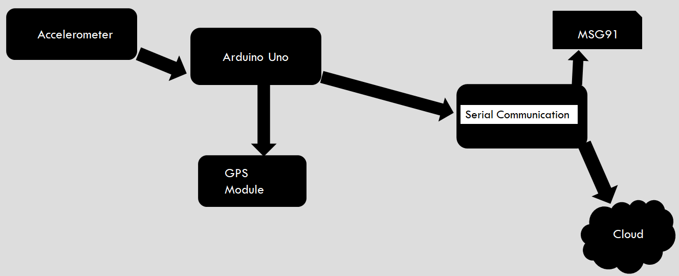
In this Automatic Vehicle Accident Alert System project, we are using Node MCU, Arduino UNO, Accelerometer, and GPS module to store the location of the vehicle and to send an immediate alert message to the nearby hospitals, police stations…etc. Here we use serial communication to send the information from Arduino to Node MCU.

The Arduino receives the latitude and longitude values of the vehicle from the GPS module. The accelerometer reads the XYZ axis values. These values are read by Arduino. The XYZ values are compared with the condition given in the code to check whether the vehicle is met with an accident or not.

If the vehicle is met with an accident, latitude, and longitude values are copied to the NodeMCU, and the message is sent to the nearby police stations, and hospitals using the msg91 application. The GPS location of the vehicle is continuously stored in the IBM cloud.

Block Diagram:

Block Diagram of Vehicle Accident Detection

Hardware components:

  • Arduino
  • Node MCU
  • GPS Module- NEO-6m
  • Accelerometer- ADXL-335

Software Components:

  • Arduino IDE
  • IBM Cloud
  • msg91

Design & Development of Smart Dustbin Project

Objective:

The Smart Dustbin Project comes under the domain of Environment, Health, and Hygiene. Through this Smart Dustbin project, we aimed to build a working prototype of a dustbin whose lid opens automatically, without any contact when a person comes near it (in the range of 2 – 30 centimeters) to throw the trash. Since the process is contactless it maintains public hygiene and sanitation. Moreover, there are many instances in public places where the dustbins overflow because of irregularity in the waste collection from the dustbin (which is usually done by the municipality sanitation workers).

To overcome this issue, our next target was to provide functionality such that when the dustbin is full, it will not open at all if the person comes near it to throw the trash. Now, a sanitation worker will need to open the bin to empty the contents irrespective of whether it is full. Therefore, to unload the bin in case it is full we provided a switch that when pressed will open the lid in any case. And in this case, the lid will continue to remain open until there is an object (hand) in front of the ultrasonic sensor in the predefined range.

This Smart Dustbin product can be useful in all the places where the dustbin is frequently used and minimal or no contact is expected from the user. For example, doctors can use this in an operation theatre, flight attendants can use it while serving food, it can also be used in public toilets, etc. In countries like India, where waste management is a crucial problem, it is important to work further on such products that provide methods to collect the garbage along with maintaining proper hygiene as well as contributing to the environment.

Outcomes:

Using a microcontroller-based system, we achieved the 3 functionalities at the end of this project that we had aimed for.

1. First, we were able to open the dustbin without any contact using the ultrasonic sensor (the side sensor). It is programmed to detect motion in the range of 2 – 30 centimeters in front of it and this will open the lid.

2. The second functionality is that when the dustbin is full (it reaches a level defined in the code), it will not open even if there is movement in front of the side sensor. This functionality is helpful to resolve the issue of the overloaded dustbins which are often seen in public places all around India. The level of the garbage inside the dustbin is sensed using another ultrasonic sensor (the top sensor).

3. Finally, the last functionality is to be able to unload the dustbin when it is full. This functionality is needed because when the garbage in the dustbin reaches a particular level, after that it can not be opened even with the motion in front of the side sensor (because of the second functionality). Therefore, in this case, to unload the dustbin for reusing we added a pushbutton in our circuit.

Components Used:

  • ARDUINO – UNO
  • 2 HC-SR04 Ultrasonic Sensors – One on the cylindrical surface (Side Sensor) and the other on the lid (Top Sensor)
  • Mini/Micro Servo Motor (9 gms)
  • 4-pin push button
  • Resistor
  • 9-volt power supply
  • Jumper wires
  • Breadboard code:

Visit Here to Download the Complete Smart Dustbin project code, report, Output Video Link, and any academic project help from the project developer.

Smart Traffic Light Control System Embedded Systems Project

Abstract

Considering the heavy traffic congestion on daily basis sometimes emergency vehicles like ambulances get stuck in the congestion which complicates the situation. Normal traffic lights are not able to operate according to the requirement of emergency vehicles. So, our project aims to make them operate keeping the track of the emergency.

Design/Algorithm

We are operating the traffic light based on the interruption given by the emergency vehicle. So when it gets interrupted by an ambulance it turns off all the traffic signals apart from the one on which the ambulance is coming.
Proposed- In the Smart Traffic Light Control System project IR transmitter is being used which will transmit the code and the receiver will detect it then the microcontroller(Arduino) will get an interrupt and it will stop the normal functioning of the traffic signal and free the path of the ambulance by making the light green.
CCN components to be applied-
Source encoding and Decoding and error detection like checksum and parity Checker.

Design Schematic/Flow Diagram/Block Diagram

Components Used (S/w, H/w)

Hardware components:

• IR module
• Arduino
• Breadboard
• LEDs, Resistors
• Jumper and connecting wires

Software Used:

• Arduino(IDE)

Cost Estimation:

Around 250 if we use a general microcontroller instead of Arduino.

Work Done

Whenever there is no emergency vehicle like an ambulance, the traffic system will work as usual but when the vehicle comes it will turn on the green light (according to the program) so the ambulance will not have to wait.
For making it foolproof, source encoding and error detection are done by assigning a specific code to the ambulance.

Working Constraints

  • The traffic congestion needs to happen for deploying this technique.
  • Only aiming at VIP/Ambulance vehicles.
  • Works using IR so restricted to a particular radius.
  • Only applicable to Tier-1 cities with traffic lights already installed.

Future Scope of Project

  • In the future, this project can be implemented for every vehicle irrespective of the priority.
  • IR can be replaced by GPS modules to increase the effectiveness and span of the connection.
  • It can be used as a tracking device by the company to seek their employee’s current positions, like pizza delivery or e-kart suppliers, etc.
  • By using the tracking sensor we can implement our traffic cloud system to help users to navigate through the less clumsy path.

Obstacle Avoidance Voice Controlled Robotic Vehicle Project

This Obstacle Avoidance Voice Controlled Robotic Vehicle Project work is mainly based on Arduino, Motor driver, and Bluetooth module. Arduino is an open-source prototyping platform that is based on easy-to-use hardware and software. Arduino makes use of an ATmega328 microcontroller.

Robotics has become a major part of our day-to-day life and also it plays a vital role in the development of new technology in the engineering field. This is a simple type of remote control car, where the ordinary microcontroller has been replaced by Arduino and the IR sensors have been replaced by the Bluetooth module.

The remote device to control this device can be any android or IOS mobile phone. And in this, we have also included the ultrasonic sensor which detects any obstacle present in front if any it stops the car. This project can be made used on a large scale for real-time vehicles.

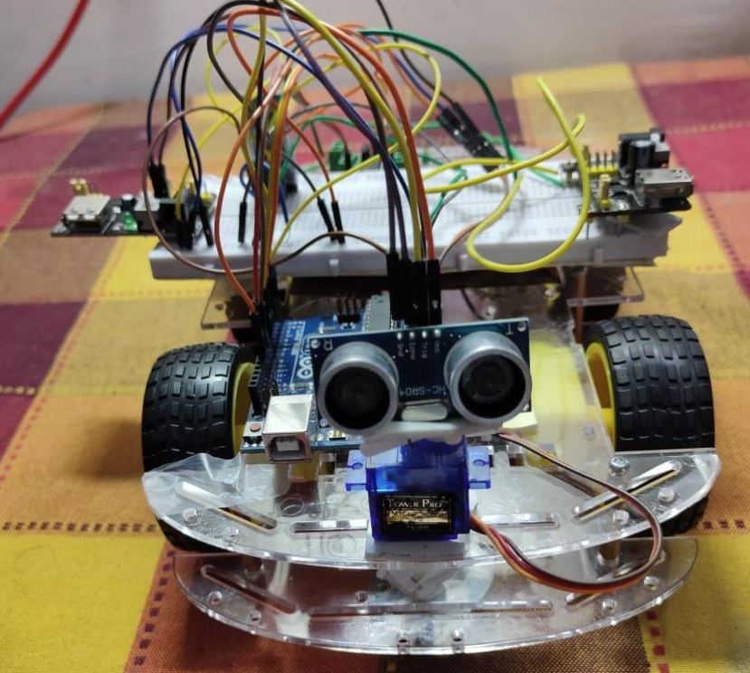
hardware implementation of the circuit diagram including ultrasonic sensor

This project is controlling cars not by using sensors or transmitters but by using Bluetooth which is a very simple medium of communication in the present day. The remote device which controls this project is an android device that has an inbuilt Bluetooth module. Through Bluetooth, we can connect two devices.

Here we have inserted a Bluetooth module that gets connected to the phone‘s Bluetooth, which allows us to communicate and allows to take control over it. The main control of the car is played by the Arduino UNO which is the micro-controller ATMEGA32. Arduino has played a major role in the robotic section and it had made it easier to convert digital and analog signals to physical movements.

This project is Bluetooth-based because it gives us a wider range of control and more efficiency. It also gives us the advantage of changing the remote anytime, so that we can use any android device including phones, tablets, and computers. Physical barriers like walls and doors do not affect controlling the car. We have also included the ultrasonic sensor which helps the bot to stop automatically when an obstacle is present before it. An obstacle detector is added to protect the system from obstacles on the way by using an ultrasonic sensor that is mounted on the servo motor.

The voice-controlling commands are successfully transmitted via Bluetooth technology and on reception; the desired operations successfully take place. This project reduces human efforts in places or situations where human interventions are difficult. Such systems can be brought into use in places such as industries, military, and defense, research purposes, etc.

Hardware components to implement this project:

  • Arduino UNO
  • Motor shield
  • Ultrasonic Sensor
  • Bluetooth Module (HC-05)
  • Servo Motor
  • Jumper Wires
  • Bo Motor 300 rpm
  • Car Kit

Download the complete OBSTACLE AVOIDANCE VOICE CONTROLLED ROBOT Final Year ECE Project code & Report.

Women Security Band – Smart and Handy Security Device for Women Project

Objective :

  • To design and develop a smart and handy security device for Women.
  • To alert people in its vicinity and relatives of the victim about the attack and also get help from emergency services.
  • To track the user using google maps under crucial situations.
  • The module developed should be capable to work automatically under crucial situations.

Introduction :

Women Security device is a device that will help women to walk freely in the streets anywhere and at any time. The goal of the women’s security device is to protect women from getting molested in different ways like rape, sexual harassment, abuse, etc. There are existing apps or devices to provide security to women but there are drawbacks to these existing apps or devices. So to overcome such drawbacks and provide security in an enhanced way we are going to propose the women’s security device.

Technical Details :

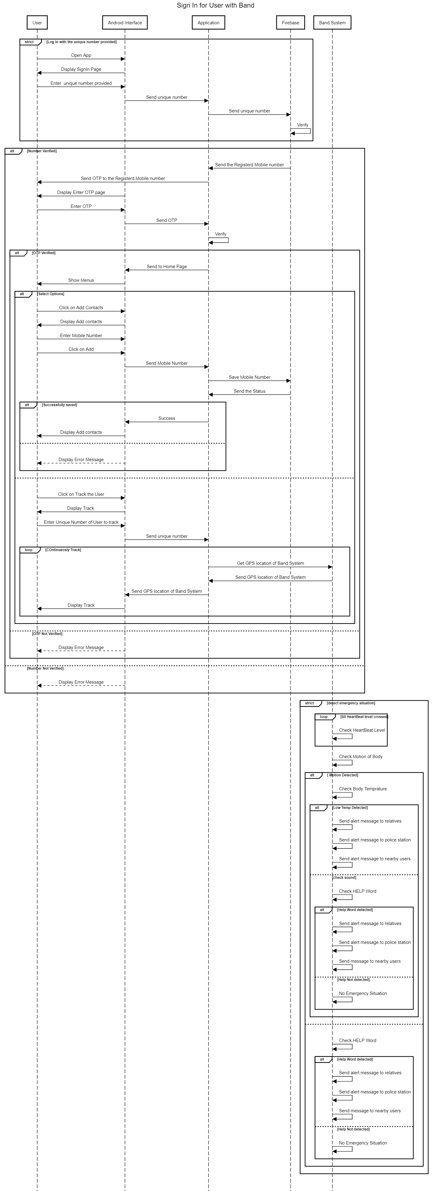
Following modules/sensors to detect the crucial situation:

1. Pulse rate sensor:

Pulse rate will be the major parameter for the security device because
whenever the person is in danger person’s heartbeat gets increased. So using this parameter we can consider that person can be in danger.

2. Temperature sensor:

This is the second parameter that can be considered when the person is in
danger its temperature starts decreasing so this can be considered as one of the parameters to detect that the person is in danger.

3. Motion sensor:

This is the third parameter we can consider as when the person is in danger due to
fear or anxiety person’s body starts shaking or shivering. So this can be considered as another parameter to send alarm message or call to relatives.

4. Voice Recognition.

We will be using this parameter as well to detect dangerous situations. We will be recording the “HELP” word and when the person shouts when is in danger then by detecting and comparing it with the already recorded word and if it crosses a certain limit of intensity range then we can consider it as a dangerous situation to send alarm message or call to the relatives of the person.

Using the above sensors will provide input to our device
Also to track the user and send emergency messages to listed
contacts and to the nearest police station two modules are used

Problem Statement

To develop an easy-to-carry system that will work automatically without any manual inputs to provide security for women.
Importance of the project.

The expected outcome of the project

A wearable security device that will be user-friendly and feature train the device according to different users. Module to add and remove authorized people for sending alerts to them. Location will be considered while sending alerts.

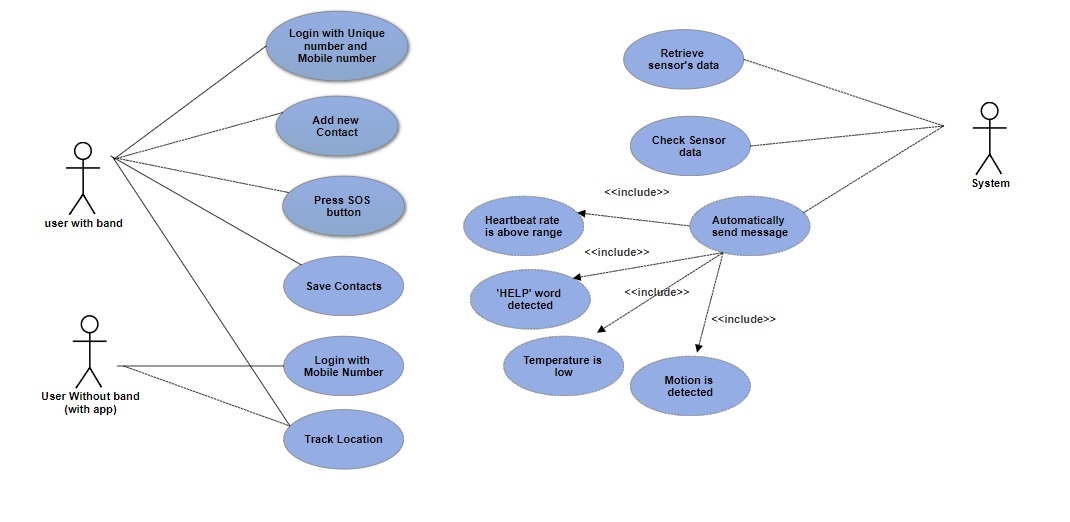
Functional Requirements:

The user of the Bracelet:-

1. System would Identify the critical situation and normal situation automatically.
2. System would get emergency help automatically when the victim is under attack.
3. System would Blink the LED for 10 secs when a critical situation is detected.
4. Track the nearby victim/friend/relative in an emergency using Google Maps.
5. System would alert the vicinity people.
6. System would get emergency help when the SOS button is pressed manually.
7. Add the contact numbers of friends/relatives on the application to ask help for in an emergency.
8. Login with the already provided unique number using the mobile application.
9. Save the button on the System to write those numbers into GSM.
10. Reset button on the System to reset all previously saved numbers into GSM.

Other than the victim/ User of the Bracelet:-

1.Log in with a verified mobile number.

2. Track the nearby victim/friend/relative in an emergency using Google Maps.

External Interface Specifications:

1. User Interface:-

The user of the Band:-

1. Login.
2. Add the contact numbers of friends/relatives.
3. Tracking the victim using Google Maps.

Other than victim/ User of the Band:-

1. Login.
2. Tracking the victim using Google Maps.

2. Database:-

Firebase Cloud will be used for real-time database storage.

3. Google Maps API will be used for tracking the user.

Technical Specification: There will be one android app and a smart band.

Languages & Technologies:

Languages: C, C++, JAVA, Firebase database
IDE: Arduino, Android Studio

Automating the Irrigation Process by Analyzing the Soil & Weather Conditions

This is Automating the Irrigation Process by Analyzing the Soil & Weather Conditions Project.

The main aim of developing this Smart Irrigation System IoT project to provide easy irrigation methods to the farmers as per the Soil & Weather Conditions.

In this project, we are using GSM Module (SIM300 Module), this is used to receive text messages from the Android app and it gives the message to the Arduino UNO board.

The Job of the Arduino board is to read messages from the GSM and it will process the output for the motors and it will also tell us the status of the soil moisture, temperature, and humidity in the agriculture field.

Smart Irrigation System IoT project

This project 2 Modes

In Auto mode, it detects the soil and if it is dry The motor will be on and If it is wet then the motor will be off.

and can swich on/off the pestiside motor also.

In Manual Mode, the farmer can switch on the motor manually with the help of the Android app.

Whatever the messages We send via an Android app, The GSM receives and it sends to the Arduino UNO board over serial communication.

from this Arduino we have 2 Relays, Relays are nothing but electromechanical switch. This Arduino giving a signal to the relay board.

The below is the working procedure of the Smart Irrigation System project.

https://www.youtube.com/watch?v=1xkAC9r6Dqc