IOT Solution for Vehicle Maintenance and Report Generation System

INTRODUCTION

  • Many automotive manufacturers are now moving towards an IoT platform for manufacturing and for service purposes.
  • The main advantages of using IoT in cars are Optimized maintenance and logistics.
  • Our idea is to monitor vehicle status (fuel, efficiency/Km, battery, oil levels, etc..,.) to the customer as well as the manufacturer.

CONCEPT

  • The main aim of every car manufacturer is to increase the life of the car and it’s crucial to maintain the car in a good condition to achieve it.
  • Many problems in vehicles arise due to improper maintenance. Many lose track of their service status and it’s a tiring process to keep in touch with every customer in a large automotive industry.
  • If we maintain a system, that automatically updates the vehicle’s conditions periodically to a specified server, and the system will generate a report, that will be forwarded to the customer and the service team, a lot of manual work will be removed.
  • We as a team provide an IoT solution for vehicle maintenance and report generation system.

FLOW DIAGRAM-FUNCTIONAL DECOMPOSITION

  • Our Vehicle Maintenance and Report Generation system collects data from the sensors available in the car itself and reports it to a transceiver module(ESP8266) which is connected to a database in the cloud.
  • when new data is updated/inserted into the table an event is triggered. This event updates the information in the dashboard, which will be displayed to the customer and manufacturer.
  • Then a weekly/monthly/yearly report generation event is triggered, which will mail the report to the specified recipient.

FUNCTIONAL DECOMPOSITION

Data collection:

The data is collected from the sensor stream of the car. This data is redirected to the ESP8266 module. The ESP8266 is connected to the server, that is allotted to the car. The ESP8266, when all data is collected, converts it into a JSON file. Then the server sends a post request to the server.

Event trigger:

Many database servers provide pl/SQL-based triggers. Here an Update and Insert trigger is created for the table. Oracle server provides a wide range of PL/SQL functions. The IP of ESP8266 is connected to the oracle server, which on periodic updates in the table triggers an event.

Dashboard:

The dashboard is created using HTML and CSS and deployed in the cloud using the NODE JS framework.

FUNCTIONAL SPECIFICATION
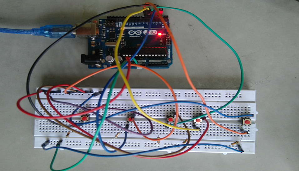
Hardware:

ESP8266 CP2101 module(CAR)
ESP8266 CP2101 module(HOME)

Programming Language:

SQL
Javascript (Node JS)
C++(Arduino .ino)
HTML CSS

Dashboard

The Vehicle Maintenance and Report Generation System dashboard are developed using Adafruit.io. This website provides dashboard development for MQTT-based devices

Cloud and IoT Based Health Monitoring System Project

Objective

Our system is useful for monitoring the health system of every person by easily attaching the device and recording it.

We can analyze patients’ conditions through their past data, IoT sensors are being utilized to consistently record and monitor health conditions and transmit alerts in the event that any uncommon signs are found.

If there should be an occurrence of a minor issue, the IoT application additionally has the arrangement to recommend a medicine to the patients.

Introduction

This project is the solution to be able to make use of IoT sensors and actuators to be able to detect issues with subscribed patients remotely to be to monitor health, emergencies, statistics, etc, This makes use of Cloud, Machine learning, IoT platforms, and devices.

The results can be recorded using Arduino.

The doctors can see those results on an application. The system will also generate an alert notification which will be sent to the doctor.

Literature Survey

  • Smart Health Monitoring Systems: An Overview of Design and Modeling
  • Cloud-Based Privacy-Preserving Remote Monitoring and Surveillance
  • A Review of Machine Learning and IoT

Architecture Design

The Flow diagram for Cloud and IoT based Emergency response system follows Sensing, Processing Unit, Cloud Server and Analysis.

Hardware  and Software Requirements:

Arduino: 

IoT Sensors: The main purpose of sensors is to collect data from the patient’s body and from the surrounding environment. 

Cloud: These cloud computing platforms are used to store the data and perform some analysis on the data which is stored on the cloud.

Product Perspective

User Classes and Characteristics

The main objective is to design this System with two-way communication i.e. not only the patient’s data will be sent to the doctor through SMS and email in emergencies, but also the doctor can send required suggestions to the patient or guardians through SMS or Call or Emails.

The user base for this application involves patients and old age people.

Assumptions and Dependencies

Appreciable accuracy in IoT sensors to fetch accurate data. 

Reliable internet connections. 

User Interfaces

Front-end:

  • Web application
  • IoT sensors

Back-End:

  • Open Source IoT platform

Functional requirements

  • Sensors frequently detect data from patients.
  • Collected information is updated in the cloud.

Performance Requirement

The data analysis and communication (response) between the user device and subscribed user must be quick.

Conclusion

The primary purpose of a  health monitoring system is to allow people to lead independent and active lives in their familiar home environment while ensuring continuous, non-invasive, non-intrusive, and seamless surveillance of their health and physical well-being. Continuous monitoring of health status can provide comprehensive information about individuals’ health status over a period of time.

Download the complete project Code & paper Presentation of Cloud and IoT Based Health Monitoring System Project.


Implementation of E-voting Machine Project using Python and Arduino

INTRODUCTION

Our E-voting Machine project is very useful, This Project was implemented using Python and Arduino. The user is no longer required to check his register in search of records, after the voting procedure gets over, the admin will be able to calculate the total number of votes in just one click since the entire work is done using computers. The user just needs to enter his/her unique voter ID.

In today’s world, no one likes to manually analyze the result after the voting procedure gets over because the process is time-consuming and of which results get usually delayed. Everyone wants his/her work to be done by computer automatically and displaying the result for further manipulations. So this E-voting Machine project is about providing convenience regarding voting.

OBJECTIVE

  • Our objective for the E-voting Machine project is to make a user-friendly Electronic Voting Machine that makes the current voting process faster, easier, and error-free.
  • We have used Arduino in our project for the implementation of push buttons and Python as a programming language.

PROBLEM STATEMENT 

The problem statement was to design a module:

  • Which is a user-friendly E-voting Machine
  • Which will restrict the user from accessing other users’ data.
  • Which will ease the calculations and storage of data.
  • Which will help the jury to declare the result without any biasing.

FUNCTIONS TO BE PROVIDED:

The E-voting Machine system will be user-friendly and completely secured so that the users shall have no problem using all options.

  • The system will be efficient and fast in response.
  • The system will be customized according to needs.

FOR e-VOTING SYSTEM

  • (Check
  • Store
  • )

SYSTEM REQUIREMENTS

  • Programming Language Used: Python, C
  • Hardware Used: Arduino UNO
  • Components Used: Push buttons, Connecting Wires, Resistances(100k ohm), Breadboard
  • Software Used: Anaconda 2.7.x, Python 2.7.x, Arduino IDE
  • Modules Used: Serial, SQLite, Tkinter, tkMessageBox

WORKING

  • The user has to enter his/her ID in the system.
  • After verifying the user ID, the system will show a message that whether a user is eligible to vote or not after checking his/her details stored in the system.
  • A message will be displayed accordingly. The user will then have to press the button against which the name of the candidate is written and whom he/she wants to vote.
  • The votes hence are stored in the database and the results will be announced accordingly.

FUTURE SCOPE OF THE PROJECT

My project “e-VOTING SYSTEM” will be a great help in conducting voting at various organizations. So the modifications that can be done in our project is to add one major change which can be done in this project is to add the data of the voters. This will result in the total identification of the voter.

CONCLUSION

From this E-voting Machine project, we can conclude that this program is very useful in conducting the voting procedures smoothly. It provides easy methods to analyze the voting result. It helps in conducting faster, more secure, and more efficient voting. The program can be used per the norms of the voting requirements.

Download the complete project code, report, and PPT on E-voting Machine using Python and Arduino.

Two Wheeled Self Balancing Robot Minor Project Synopsis

Introduction

The basic working principle behind a self-balancing robot is an inverted pendulum concept model in control theory, according to which the robot drives the wheels in the direction in which it tilts. Examples of the inverted pendulum in certain real applications include rockets like MAXUS, Segway the personnel transporter, and a self-balancing vehicle.

It has great advantages like small size, flexibility, and low cost because of these advantages, it can be used in various applications in the field of control engineering. The inherent complexity associated with the control of this platform finds its application in the design and development of control systems for automobiles, spacecraft, and transportation facilities including military transport.

The developed hardware is used to develop an object-carrying vehicle that can be used to reduce human efforts in working places, offices, and household applications.

This is a cost-effective solution using the PID algorithm for these two-wheeled vehicles.

Rationale

Because of the previously stated advantages that come with a two-wheeled self-balancing design, a number of consumer products have recently gone mainstream that utilize a similar idea for purpose of convenient human transportation, i.e. – Hover-boards, Segway, and self-balancing two-wheelers. Our goal with this project was to demonstrate the balancing mechanism used in these products in a compact, cost-effective prototype of a self-balancing robot.

Objectives

1. To balance the whole body on two wheels automatically by designing the best possible structure for the body and obtaining the filtered values from the gyro and accelerometer sensor i.e. – mpu6050.
2. To use inbuilt Wi-Fi or Bluetooth capabilities of ESP32 microcontroller to communicate with the robot in order to de- liver the commands to follow.
3. To fine-tune custom PID values for the robot to ensure its smooth maneuverability.
4. To generate the ability to balance and maneuver with objects placed on its head

Feasibility Study

1) Feasibility of the project

The project is intended to explain the design along with the construction and control mechanism of a two-wheel self-balancing robot. To deal with the problem of sudden horizontal movements and gyro drifts in sensors, a complementary filter is implemented[1]. PID (proportional integral derivative), is the feedback mechanism used for this project.

2) Need of the project –

1. Its ability to turn on the spot and sustainable architecture increases its applications in industries.
2. It is essential for the robot to not only balance but also maintain its position, withstanding external forces or unexpected disturbances if any

3. Active research on two-wheeled robots has been widely increased since the early versions of the studies on self-balancing robots by JOE and n-BOT.

3) Significance of the project –

These robots can be used for

1. Smart gardening purposes.
2. Autonomous trolleys in malls, hospitals, and airports.
3. An intelligent robot for various industrial-military purposes.

4. Currently popularized as “Segways,” these machines are mostly used for travel and tourism purposes and by private security services. It has been put to use by a range of private and military organizations since its invention.

Methodology/ Planning of work

The main objectives of a system for Online voting system are:

1. The objective of the Online voting system is to help the organization in automating the whole manual processing of the existing system.
2. Test the working and compatibility of all electronic components (mpu6050 and motors and its driver) with ESP32 separately and ensure the proper working of each component. a rudimentary prototype using all components with temporary wiring on the breadboard in order to test the integrated working of the components with each other (without tuning PID values).
3. Fabricate the basic frame of the robot using acrylic sheets, spacers, screws, and angle brackets.
4. Mount all electronic components onto the frame.
5. Make wired connections according to the planned circuit.
6. Upload code to ESP32 from Arduino IDE.
7. Update PID values.
8. Test the performance, balance, and maneuverability of the machine, if not satisfied with its performance, go to the 7th step in order to fine-tune PID values else the required development of the robot is completed.

Facilities required for proposed work

Software Requirements:-

1. Arduino IDE

Hardware Requirements:-

1. Arduino IDE
2. ESP32 microcontroller – 1
3. MPU6050 sensor – 1
4. Bo geared motors – 2
5. L298N Motor driver -1
6. 3.7v 18650 Li-ion battery – 2
7. Assorted Jumper Wires
8. 3mm Acrylic Sheet
9. 65mm Nylon Tyres – 2
10. Angle Brackets – 2, Spacers and Screws

Design and Implement a Healthcare Monitoring and Management System IoT Project

Nowadays Internet of Things is bringing a revolution in the infrastructure of technologies. The IoT-based health monitoring system is essentially a patient monitoring system in which he can be supervised 24*7. Remote Patient Monitoring arrangement enables observation of patients outside of customary clinical settings (e.g. at home), which expands access to human services thus bringing down costs. Healthcare is given extreme importance by each country with the advent of the novel coronavirus.

Recently there has been a spike in the use of smartphones and along with that, wearable sensor remote health monitoring has evolved quickly. IoT not only helps in preventing the spread of disease but also in getting a proper diagnosis, even if the doctor is present at a remote distance By facilitating effortless interaction among various modules, IoT has enabled us to implement various complex systems such as smart home appliances, smart traffic control systems, etc.

PROPOSED SYSTEM:

The main objective of this Healthcare Monitoring and Management System is to develop, design, and implement a smart patient healthcare monitoring system. The sensors used here are embedded in the body of the patient to sense the parameters like the heartbeat and temperature. These sensors are connected to a master unit, which calculates all of their values. These values are then transmitted by leveraging IoT cloud technology, to the base. From the base station, these can be easily accessed by the doctor present at some other location. Thus based on the temperature and heartbeat values, the doctor can decide the state of the patient and appropriate measures can be taken.

OBJECTIVE:

Monitor patient parameters remotely to increase the efficacy of healthcare management systems

IDEATION:

We need to monitor the patient parameters from remote distances using various sensors. The data given out by the sensors are then sent over to the cloud for further access via a Wi-Fi module (inbuilt or externally connected). This is being done to reduce the critical time of testing patient parameters before any major operation.

Here we are measuring the temperature and pulse parameters of a patient remotely.

Components required:-

MLX 90614 Temperature
MAX 30102 Pulse Rate
Jumper wires.
Nodemcu ESP8266 board

The Gantt Chart is shown below:-

smart patient healthcare monitoring system

Summary:-

 Health care is given extreme importance nowadays by each country with the advent of the novel coronavirus. Thus in this regard, an IoT-controlled healthcare monitoring system is most probably the best solution for such an epidemic. Internet of Things (IoT) is the new revolution of the internet which is a growing research field, especially in health-related services.

“Healthcare Monitoring and Management System” is the project where we have mainly focused on two objectives first one was a smart health monitoring system, to collect the health history of patients with a unique ID and store it in a database so that doctors need not spend much of their time in search of the report and give analysis right from the dashboard. Any health care that is being done will be updated and reflected in the dashboard itself. And the other one is the Wearable-Sensor-Based Fall Detection System for aged people, to monitor their movements of them, recognize a fall from normal daily activities by using sensors, and automatically send a request or an alert for help to the caregivers so that they can pick up the patient.

However, there are a few shortcomings to this too. Basic knowledge of the operation is to be learned by the caregivers. Also, both the caregiver and the wearer should know how to protect the sensors from water damage or any physical damage. 

  • Planning and project management 

S.No.

Activity

Starting Week

Number of Weeks

1.

Literature Review

1st week of January

 2

2.

 Project Finalization

3rd week of January

 1

3.

Required software setup

4th week of January

 1

4.

Gathering of Hardware & Formation of codes

1st week of February

1

5.

Hardware assembly calibration

2nd week of February

 1

6.

Code Integration & Debugging

3rd week of February

 2

7.

Inclusion of IoT and Blynk

1st week of March

 1

8.

Finalization & modification of Website and mobile application

1st week of March

 1

9.

 Preparation of project report

2nd-3rd week of March

 2

10.

Preparation of Project presentation

4th week of March

1

Raspberry Pi Project on Intelligent Door Access Management System

Today the world has been far more advanced in technology than in the last 3 decades and with that, there are advances in the technologies that help to keep our homes safe. With the help of IoT now we can track our house even when we are on vacation.

The significance and the purpose of our Door Access Management System are to make the user’s home much safer by increasing security and giving the user full control of the system.

Introduction

Background of Project

When we are at work, we may have an important meeting and may not be in time to receive our guests and they may need to wait outside. The same may happen if we are on a vacation and to safeguard ourselves from Intruders.

The duty of an Engineer is to provide solutions for the problems faced every day with upcoming technologies and we have come up with a model which will help to solve them.

Statement of the problem

This project will create a smart doorbell messaging system so that when a guest clicks on the button, obtains an image of the user via a camera peripheral, uploads the image and event data to a Googles Firebase cloud, and sends a message with some message to notify that a guest has arrived.

Aims and Objectives of the project

The main objective of the project is to make a Smart door system. The other objectives are: –

  • To include an access button to allow the user to open/close the door

Materials

The main components of the Intelligent Door Access Management System are as follows:

  • Raspberry pi 3    
  • Push-button 
  • Logitech Camera                                                     
  • Stepper motor

Working

The first step was to make an interface between the Push button and the Camera using Raspberry Pi so that when the button was pressed the camera would take a picture. The next step is to connect the camera to the Firebase Cloud to upload the images in the Firebase Storage and send the image’s URL to the Firebase Database.

Next using Android Studio, a Mobile application was designed to retrieve the image from the Firebase Database. Using Node JS push messaging is also added along with the mobile app such that when someone is at the door a notification pops out. They can Open or Close the door using the buttons in the app. When pressed the data is sent to Firebase Database and retrieved by the Raspberry Pi which then operates the door.

Flow Diagram

Block Diagram of Door Access System

Bill of Materials:

Materials

Cost (in Rs.)

Logitech camera

1350

Raspberry Pi 3B

3500

Micro-Stepper motor

400

Push Button

50

Contingency

700

Total

6000


Future scope

  • Face recognition can be implemented to allow family members /regular guests
  • It can be integrated with a burglar alarm and inform the police of intruders 

Conclusion

The project “Intelligent Door Access Management System” has been tested real-world scenario and the door is opened or closed by the commands given by the user

Development of IoT Project on Intelligent Cargo Management System

The integration of such sensors in cargo has paved the way for intelligent transportation. These integrated systems are competent in delivering reliable details about the quality of the goods during their depository time.

To reach this goal, we use a variety of sensors suited for monitoring the safety of food products and goods by recording the transition of parameters like temperature, humidity, and air quality, fire detection.

This information is transmitted wirelessly to the IBM cloud providing an interface where the authorized person can observe the product quality over time and also receives alert messages in case of bad air quality and abnormal conditions.

Block Diagram:

Block Diagram of Intelligent Cargo Management System

An Intelligent Cargo Management System app is designed for selecting the type of goods to be stored in the truck, for door automation, and for retrieving the values from the sensor.

Initially, the authorized person of the truck has to select the type of goods stored in the truck through the Cargo Management System app. Based on the selection, the temperature and humidity values at which the goods are supposed to be stored will be known. Using the DHT11 sensor, the actual temperature and humidity inside the truck can be known.

The temperature and humidity values can be obtained from the app. By comparing these values, a message will be sent to the authorized person asking him/her to turn on the AC or the heater in any abnormal conditions.

The air quality inside the truck is constantly monitored using MQ135 sensor. If the quality of the air inside the truck is bad, a message is sent to the authorized person regarding the same.

Through this goods can be maintained in constant conditions and their quality is maintained for a longer time. A fire sensor is also deployed in the truck to detect fire. If the fire is detected, the buzzer rings alerting the driver of the fire. The door of the truck is automated using a servo motor.

The authorized person of the truck can open or close the door of the truck using the Cargo Management System app.

GPS-based Child Tracker with Emergency Text Alerts IoT Project

The hectic life of parents makes it very difficult to personally look after the kids. To overcome the problem of personal monitoring of children, we have come up with the idea of a GPS-based tracker with text alerts when the child is not present in the specified region.

Problem Statement:

To solve the problem of difficulty in keeping a check on children while they are playing in open areas while letting the children have their freedom to play from constantly being mocked by parents and to monitor the whereabouts of children by working parents. There is a similar project on Women Security System that can be seen here

Project Working Process:

Hardware Components

  • Arduino UNO
  • GPS Module
  • GSM/GPRS Module 

Software’s Used

  • Arduino IDE
  • Android (MIT App Inventor)

In this context, the solution we propose is a GPS-based Child Tracker with Emergency Text Alerts android application that can help parents in tracking the presence of their children. This application works with the help of android mobile-enabled with the ‘SMS’ feature and ‘Global-Positioning System (GPS)’ on the GSM network.

This Child Tracker with Emergency Notifier application works in two ways, the first is GPS-based is related to Location services, and the second is SMS-based which is related to Network services. In case when the Location-based services not working then the application alternatively use Network-based services that can send and receive messages.

Block Diagram:

CHILD TRACKER WITH EMERGENCY NOTIFIER Block Diagram

The GSM and GPS module is connected to Arduino Uno. The GSM module has a sim (data) through which we can receive message alerts and the GPS helps to track the location.

The data is sent to the cloud from GSM using AT commands and HTTP. The cloud is connected to the mobile app and the data is displayed in the app installed on the parent’s mobile.

Useful Projects on Self Security in Emergency Situations:

Self Security through GPS based Protection System

Stay Safe Women Security Android App Project Report

The GPS-based Child Tracker with Emergency Text Alerts app is integrated with maps and geo-fence.

The GPS is connected to Arduino using a VCC pin, GND pin, RX pin, and TX pin. Connections: VCC to 3V3, GND to GND, RX to TX, and TX to RX respectively. GSM is connected to Arduino using VCC, GND, RX, and TX pins. Connections: VCC to 5V, GND to GND, pin 3 to TX, pin 4 to RX respectively.

A tiny GPS++ library is included. Using IBM cloud (node-red flow editor) the data is sent to a mobile app developed using MIT app inventor.

Home Safety and Security System Using IoT Project

The main objective of the Home Safety and Security System Using IoT project is to implement a home safety and security system with the following features:

  • Monitoring and detection of leaks in LPG gas
  • Unauthorized opening of door/window

Hardware Requirements:

The hardware for the project consists of:

GISMO-V board with:

  • ESP32 dual-core 32-bit processor with Wi-Fi and BLE
  • MQ6 sensor module
  • Magnetic switch assembly
  • 0.96” OLED display with 128×64 resolution

Cloud Platform:

In this project, we are going to use Google’s firebase as a cloud database. It is a No-SQL database in which data is stored as Key-Value pairs.

To access the database the following credentials are required

  • Host URL
  • Database authentication key

These credentials are put into the ESP32 firmware to access the Google Firebase.
The keys used to store the parameter values in the project are:

  • IOTLAB/HSSS/Gas_Leak
  • IOTLAB/ HSSS/Window_Open

Mobile App:

  • The Modular rapid mobile app development utility is used for the development of the mobile app. The utility has two modes, a Developer mode, and a Blocks mode. Different functional blocks are available in developer mode, they are – User Interface, Sensors, Connectivity, Firebase, and so on.
  • In the Blocks mode, a timer with timing set to two seconds will fetch the LPG gas concentration and magnetic switch status values from the Firebase database and fill it in the appropriate place in the UI.
  • To access the Firebase dataset its credentials will be placed in the Firebase component of the Modular app.

Mobile App development of Home Safety and Security System Using IoT Project

Results and Conclusions:

With the help of the MQ6 sensor and magnetic switch, we monitored the leakage in LPG gas and also the window/door open status.
We can get notified with the help of the mobile app.

Download the complete Home Safety and Security System Using IoT Project code, report, ppt, design document, and SRS.

Design & Development of Smart Dustbin Project

Objective:

The Smart Dustbin Project comes under the domain of Environment, Health, and Hygiene. Through this Smart Dustbin project, we aimed to build a working prototype of a dustbin whose lid opens automatically, without any contact when a person comes near it (in the range of 2 – 30 centimeters) to throw the trash. Since the process is contactless it maintains public hygiene and sanitation. Moreover, there are many instances in public places where the dustbins overflow because of irregularity in the waste collection from the dustbin (which is usually done by the municipality sanitation workers).

To overcome this issue, our next target was to provide functionality such that when the dustbin is full, it will not open at all if the person comes near it to throw the trash. Now, a sanitation worker will need to open the bin to empty the contents irrespective of whether it is full. Therefore, to unload the bin in case it is full we provided a switch that when pressed will open the lid in any case. And in this case, the lid will continue to remain open until there is an object (hand) in front of the ultrasonic sensor in the predefined range.

This Smart Dustbin product can be useful in all the places where the dustbin is frequently used and minimal or no contact is expected from the user. For example, doctors can use this in an operation theatre, flight attendants can use it while serving food, it can also be used in public toilets, etc. In countries like India, where waste management is a crucial problem, it is important to work further on such products that provide methods to collect the garbage along with maintaining proper hygiene as well as contributing to the environment.

Outcomes:

Using a microcontroller-based system, we achieved the 3 functionalities at the end of this project that we had aimed for.

1. First, we were able to open the dustbin without any contact using the ultrasonic sensor (the side sensor). It is programmed to detect motion in the range of 2 – 30 centimeters in front of it and this will open the lid.

2. The second functionality is that when the dustbin is full (it reaches a level defined in the code), it will not open even if there is movement in front of the side sensor. This functionality is helpful to resolve the issue of the overloaded dustbins which are often seen in public places all around India. The level of the garbage inside the dustbin is sensed using another ultrasonic sensor (the top sensor).

3. Finally, the last functionality is to be able to unload the dustbin when it is full. This functionality is needed because when the garbage in the dustbin reaches a particular level, after that it can not be opened even with the motion in front of the side sensor (because of the second functionality). Therefore, in this case, to unload the dustbin for reusing we added a pushbutton in our circuit.

Components Used:

  • ARDUINO – UNO
  • 2 HC-SR04 Ultrasonic Sensors – One on the cylindrical surface (Side Sensor) and the other on the lid (Top Sensor)
  • Mini/Micro Servo Motor (9 gms)
  • 4-pin push button
  • Resistor
  • 9-volt power supply
  • Jumper wires
  • Breadboard code:

Visit Here to Download the Complete Smart Dustbin project code, report, Output Video Link, and any academic project help from the project developer.