Rocker Bogie Suspension System Mechanical Project

Abstract

The aim of this Rocker Bogie Suspension System project is to develop a surveillance robot for defense which is capable of moving in all surfaces and is capable of driving in rock terrains and live video streamlining with help of a camera.

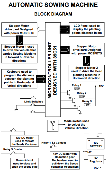
This robot has a special mechanical structure which is capable in driving rock terrains which is only possible with chain robot, but chain robot has some bugs and to overcome those bugs we designed a mechanical structure as following in figure

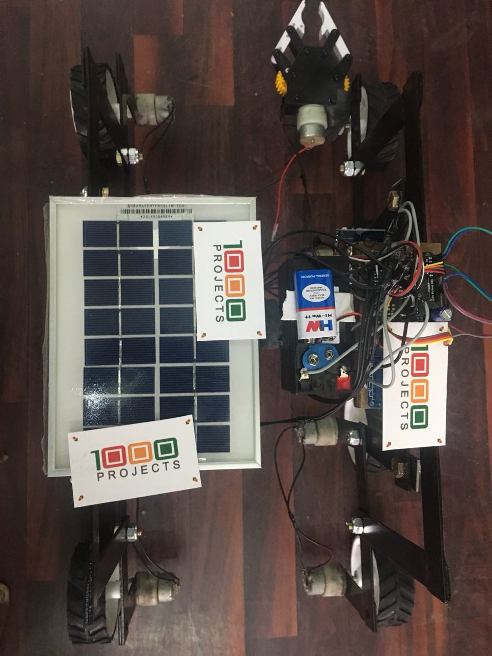
Coming to the mechanical structure of this robot it contains 8 wheels which are derived with DC motor and these motors are fixed to aluminum plates which are 220mm length, 30mm width, and 3mm thickness this has 12mm drill in the center for fixing C shape wing.

The shaft in the center is for balancing the mechanical structure for either side of robot There is push rod mechanism on either side of the robot which is helpful in limiting suspension height when driving terrain rocks which is also adjustable manually as per the requirements.

In this project we used some aluminum material as well as metal steel depending on the mechanical structure where it needs more strength and weight in particular area used metal steel material and remaining place aluminum is being used.

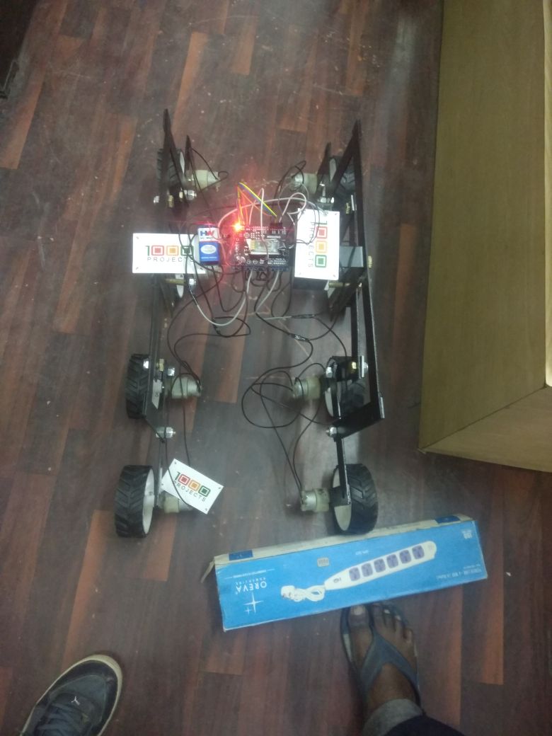
This is the Rocker-Bogie Suspension System with the dual bogies and this has the rocker in between to protect the vehicle from over collapsing

  • Existing model was in 6 Wheels
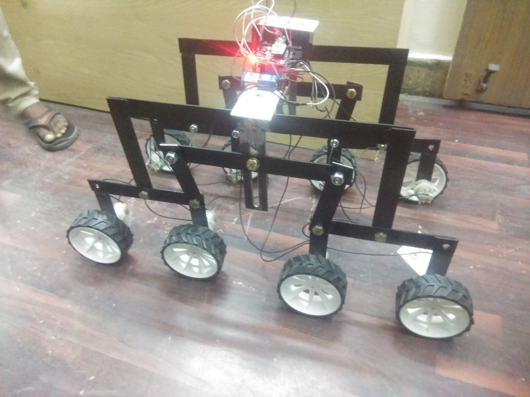
  • Proposed System is with 8 Wheels which can protect itself from over falling
  • This can be controlled via the android app with the help of Bluetooth Network.
  • This can be navigating multiple terrains in uneven surfaces can travel in mud areas
  • We have developed the entire robot in MS Sheet.
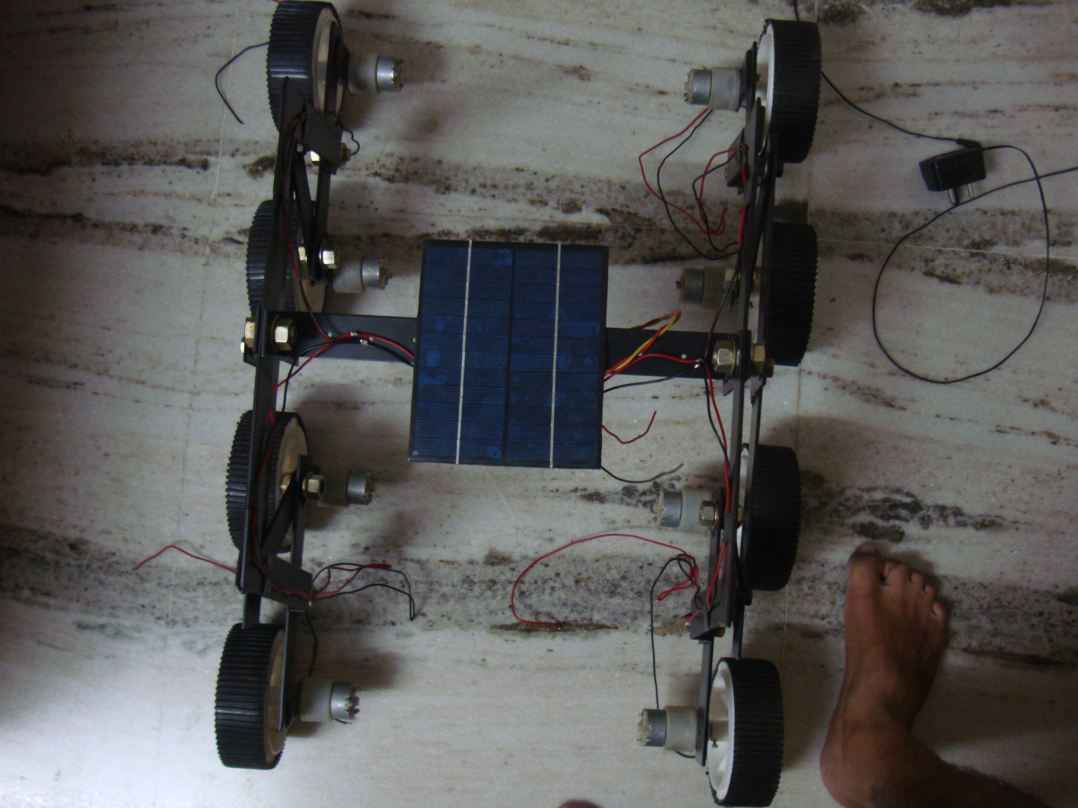
  • The below Project is solar based Rocker-Bogie Suspension System with Gripper attachment.
  • The previous one is for surveillance Purpose and this one for pick and place operations

Air Pollution Monitor Mechanical Project Abstract

OBJECTIVE: The goal of this project is to measure pollution in the air.

BRIEF METHODOLOGY:

This project was designed with an air pollution sensor, a virtual analog converter, an amplifier and a microcontroller with liquid crystal display. In this system, we use the atmospheric pollutant sensor to measure the pollutants that mix in the air.

It is the only type of sensor that acts as a transducer. It will produce a voltage output that corresponds to the degree of contamination, so it measures the pollutants inside the air and depends on the pollutants that generate the voltage pulse.

These pulses are at the millivolts level. therefore, will be given to the amplifier unit. The amplifier unit includes the operational amplifier. the small received voltage pulses are amplified at a certain voltage level, then the amplified voltage alerts are assigned to the ADC. This is the amplification stage of up to five volts Adc is no more than an analog-to-digital converter.

It is far the eight-bit converter. therefore, the corresponding virtual signals and signals are sent to the microcontroller. here the microcontroller can be atmel89c51 or PIC microcontroller, both are a reprogrammable flash type microcontroller in which we must write an embedded application to receive the ADC indicators and the corresponding variety of contaminants can be displayed on the LCD screen.

In the software program, we can write a set of rules to convert small changes of tension in the percentage degree of pollution.

Scope:

This challenge could be very helpful in the current situation due to the fact that so many people nowadays use cars because the variety of carbon in the air is high. This is very dangerous, it can have an effect on the human body, specifically, it causes diseases of the heart and lungs.

Some manufacturing units also deployed carbon nitrate in the air. then this task measures the combined pollution in the air.

BLOCK DIAGRAM:

Demonstration of a Lighting System for a Motor Vehicle

This project has the three main modules

Application of Practical Shop Processing – Applicable Products
Lighting System of an Automobile – Demonstration Model
Parallel Clamp – Applicable Equipment

OBJECTIVE:

The main aim of the project is to have set up experience on demonstration of a lighting system for a Motor vehicle by studying the basic components of the lighting system and the operation of the lighting circuit.

USEFULNESS:

Traffic regulations require every Motor vehicle to be fitted with a correct lighting system. The lighting system is also important for an automobile to drive safely at day or night.

Unless lighting system has been used or insufficient components being applied, it will be very dangerous for the vehicle. By demonstration set of a lighting system for an automobile may support much more knowledge of this system to the students who study the concerning engineering subjects.

APPARATUS:

Types of lamps required are;

Main components

  • Headlamps
  • Tail lamps
  • Side or Parking lamps
  • Stop lamp

Accessories

  • Warning lamps
  • Fog lamps
  • Panel lamps and
  • Interior illumination lamps

Types of switch constituted in the lighting system are:

  • Light switch
  • Dip switch
  • Stoplight switch

CONSTRUCTION: (WORKING PROCEDURE)

Panelboard is made of wood which has a length (3 ½ ′), wide (2 ½ ′) and thickness (¼″).

The circuit diagram is drawn on the panel board.

Complete Circuit Diagram

  • The set of apparatus is set up according to circuit on panel board.
  • The apparatus is connected to wire. After the setting has been established, the circuit is connected to the battery.
  • And then, the lighting system for an automobile which display on the panel board can be started for its demonstration.
  • Some of the other components are not display on the demonstration model board due to cost factor.

The following are the components’ specifications:

Sr.No. Components No. Required Specifications
1 Battery 1 12V
2 Head lamps 2 100 watt
3 Tail lamps 2 5 watt
4 Parking lamps 4 5 watt
5 Dip Switch 1

CHOOSING CABLE SIZE

CIRCUIT CABLE SIZE MAXIMUM CURRENT
SWG (size of wire gage) CARRYING CAPACITY
Battery and generator main feeds 44/0.012

28/0.012

14/0.010

27.5 amps
17.5 amps6 amps
Other main feeds

Remaining circuits

Starter circuits

37/0.036

61/0.036

61/0.044

According to circuit length and vehicle operating conditions

Firstly, it is calculated the current of headlamp and tail lamp. And the size of wire is selected from the table by comparing the result of current.

OPERATION:

THE LIGHTING CIRCUIT SYSTEM CONNECTION

  • The battery is connected to the battery terminal of the light switch. The light switch is connected to the dip switch including full terminal and dip terminal connected to the head lamp’s each terminal respectively.
  • Side terminal is connected to the side lamp or parking lamp.
  • The tail terminal is connected to the tail lamp.
  • The light switch control headlights, park sidelight, and tail lights.
  • The dip switch enables the head light to be changed from dip to full beam, and vice versa, without affecting the park-light or the rear light.
  • It should be noted that the stop lights will operate only when the ignition switch is on. Fuse is common practice to insert a fuse in the circuit of interior lights as on driving hazard is caused by the failure of the use in these circuits.

SWITCH OPERATION

  • Naturally, during the right-driver, and in an emergency in the day-time, the full beam of the headlamp must be used and the number two-step of the light switches on. When faced with another vehicle, the dip beam is used so is not to dazzle the driver of that vehicle. Then the dip switch is used.
  • When the number one step of the light switch is on, the parking lamps, the tail lamps and the number plate lamps all light up at the same time.
  • As soon as the ignition switch is on, the brake lamps become operational and light up when the break is applied.

HEADLAMP ALIGNING AND FOCUSING

Headlamps must be correctly focused and aligned if the driver is to have good road illumination in the right place without dazzling another road user. They are the following.

  • Front of vehicle to be square with screen.
  • Vehicle to be loaded and standing on level ground.
  • Recommended distance for setting at least 25 ft.
  • For ease of setting one headlamp should be covered.

CIRCUIT CONNECTION DIAGRAM

Parking Lamp & Stop and Tail lamps & Number Plate lamp

PROJECT PHOTOGRAPHS

REFERENCES 

1. J.A Dolan, AMSE, AMJED, 1996, Mortor Vehicle Technology and Practical Work Volume-1, lecture note in Mech. Eng: Dept., Ashton under Lyne College of Further Education Landon
2. R.E Owen, 1965, Electricity for Mortor Mechanics, Government Printer, Wellington, Newzeland.

Design & Analysis of IC Engine Components

Abstract:

  • IC engine is the major component in any automobile
  • IC engine is not just a single component, it is an assembly of various components
  • It is very important to know how much pressure, load & stresses are acting on those parts and also the effect caused due to these parameters must be estimated
  • So, we have selected 3 components of IC ENGINE
  • The 3 components are PISTON,CRANK SHAFT & CONNECTING ROD
  • IC Engine Components Designed those components in pro-e
  • And finally we analyzed them in ANSYS so as to estimate the best material

Introduction:

  • The internal combustion engine is an engine in which the combustion of a fuel (normally a fossil fuel) occurs with an oxidizer (usually air) in a combustion chamber
  • In IC Engine chemical energy is converted into mechanical energy
  • Internal combustion engines are most commonly used
  • An IC Engine consists of hundreds of different parts, which are important for its proper working.
  • However, the main components which are important are described below.
    1. Cylinder
    2. Cylinder head
    3. Piston
    4. Piston Ring
    5 . Connecting Rod
    6. Crank shaft
    7. Crank Case
    8. Fly wheel etc.
  • Here we have considered 3 main parts namely,
    1.Piston
    2.Connecting rod
    3.Crank shaft

Result and conclusion :

Through the structural analysis of the parts individually it is clear that structural steel can withstand more stresses, then comes aluminum alloys when compared to normal cast iron parts.

And these results continued with assembly of the 3parts i.e. ; piston, connecting rod, crankshaft

With these results it can be concluded that the parts made with structural steels are better than that of aluminum, cast iron & aluminum is better than cast iron.

Analysis of Assembly:

Cast Iron Assembly:

Aluminum Assembly:

Structural Steel Assembly:

Future scope : 

The 3 components are PISTON,CRANK SHAFT & CONNECTING ROD which are designed in pro-e are finally going to be analyzed in ANSYS so as to estimate the effects caused due to pressure, load but thermal analysis can also be done to analyze temperature & its effects.

As there are some reasons for not completely implementing aluminum & other materials in IC engine parts, they must be overcome by extending the experiments.

Bicycle Driven Low-Head Water Pump Abstract

Many crops especially rice, need stagnant and copious supply of water for a good yield and the river ayacuts in India have been well developed for a perennial flow of water atleast during the crop season. Irrigation plays a vital role in agriculture as a leading input both directly and indirectly because the cost of other inputs like fertilizer etc. largely depend on the availability of ensured water supply in the fields.

In the Indian context, capital intensive technologies like tubewells are usually beyond the purchasing capacity of the poor farmers. Labour intensive technologies such as pedal pumps, hand pumps, rower pumps, treadle pumps, Archimedean screw pump etc. are within the reach of the poor farmer due to their lower initial and operating cost.

A Bicycle Operated Low Head Water Pump designed, fabricated and tested in this project utilizes an improvised gear bicycle with chain and sprocket drive, a scooping mechanism, pipes and related pipelines.

The device is placed near a water source and the bicycle is pedalled. Due to this rotary motion, the scooping mechanism (connected to the wheel which is chain driven) scoops water from the water source and the collected water is sent to the farmlands through pipelines.

The whole device is non-polluting and totally independent of fuel, sunlight, wind etc.. Another attractive feature of this design is that the whole machine can be detached from the common bicycle, transported to the field and erected in situ.

Suitable modifications have been done to the bicycle to facilitate the transmission of motion from the rear wheel of the bicycle to the spiral scooping mechanism attached to a separate rim. A frame has been fabricated and fixed on the hub of the rear wheel so as to lift it off from the ground and thus avoid any hindrance when the bicycle is pedalled.

The whole setup is placed either in a stream or a stagnant water source like the village tank and the bicycle is pedalled. The scooping mechanism scoops the water which is now supplied to the fields with the help of delivery pipes. The designed model has a flow rate of 240 litres/hourand a head between 0.5metres and 1.5 metres. The stresses in the various members have been calculated and the factors of safety have been found to be satisfactory.

This flow rate can be increased with addition of more scoops and spirals and also by redesigning the scoop with an elliptical cross section instead of the present conical funnel. These twin changes will, in addition to increasing the flow rate by a factor of probably ten, will ensure a more uniform load torque and hence ease of operation for the worker.

The next prototype can be designed with a much larger wheel and/or a set of wheels than in the present model. One can also imagine a tandem bicycle operable by two or more workers at a time.

It is hoped that the present Bicycle Driven Low-Head Water Pump project is another step in today’s urgent search for an energy efficient, low cost, easily maintainable, non-polluting and affordable water pump to meet the irrigation needs of the small farmer in the developing world especially since agriculture all over the world is a loss making sector and depends heavily on government subsidy.

Pneumatic Six Axis Material Handling Equipment

The current material handling processes includes complicated designs and the cost of the system is also high. Hence every industry is in need of a suitable material handling equipment which must be of low cost and also it must be flexible enough for the users.

This Pneumatic Six Axis Material Handling Equipment project serves as best for satisfying the above conditions. We used pneumatic application for the automation and it can be moved in six axis such that the entire material handling process can be automated.

WORKING PRINCIPLE

Our Pneumatic Six Axis Material Handling Equipment project consists of six pneumatic cylinders which are actuated with the help of the compressed air from the compressor. One pneumatic cylinder is attached at the bottom of the setup which is coupled with the rack and pinion arrangement and this cylinder is used to rotate the setup in 360°.

Another cylinder is placed vertically which is used to actuate the arm of the machine. The third cylinder is provided just above the vertical cylinder for achieving the raising and lowering action of the arm. The fourth cylinder is used to extend and retard the arm.

The fifth cylinder is used to raise and lower the gripper assembly. The last cylinder is used to actuate the gripper setup which is usually used to hold the work materials. Corresponding pneumatic cylinders are actuated with the help of the compressed air from the separate compressors and the material from one place in transferred to the other place with the help of this six axis material handling equipment.

This machine is highly useful since it can be moved in 360°.

2D DRAWING

ADVANTAGES

  • Simple in construction.
  • Easily available components are used.
  • Can lift heavy objects that cannot be lifted with bare hands.
  • Highly reliable.
  • No need of skilled operators to operate this machine.
  • The life of the machine is high.
  • Maintenance free system.

DISADVANTAGES

  • Semi automated machine.
  • Need separate compressor for the effective operation of the system.
  • If any one of the cylinders gets damaged, the entire operation if affected.

APPLICATIONS

These types of pneumatic six axis material handling equipment have a wide range of applications in the fields like,

  • All industries,
  • Highly suitable for assembly and packing industries.
  • All manufacturing plants.

Design and Finite Element Analysis of Wind Turbine Hub

Abstract 

One of the crucial parts in wind turbine is Hub, which experience the loads from the blades and the loads were transmitted to the main shaft.

In this Design and Finite Element Analysis of Wind Turbine Hub project extreme loads and fatigue loads cases (IEC loads) were taken in to consideration and analysis are done for the two different materials viz cast iron and aluminum alloy.

Existing material is Cast Iron GGG 40.3 which has disadvantages like Very expensive Material for casting ,  Cost of Material is so High, Weight of the Hub is huge. In the Existing Material  we have so many disadvantages, so that to overcome we have chosen the  alternative material as Aluminum Alloy  6061.

Which has Advantages like Strength to weight ratio, Gradual  Reduction in cost,  Reduction in  the weight of the hub.

Finite element analysis is used to compare the above materials with extreme and fatigue load condition as per IEC load are discussed in this Design and Finite Element Analysis of Wind Turbine Hub project.

Automatic Sowing Machine Project

The growth or development of any nation in the world is purely depends up on the agriculture production. Traditional methods of sowing seeds manually consume lot of time and also it may not be accurate because of human errors.

Maintaining uniformity in seed planting can increase the sowing efficiency, there by to over come all these problems, these days former’s are using automatic sowing machines.

In this regard to enhance the technology in the field of sowing machines, mainly to increase the sowing efficiency, this project work is taken up, which is designed as programmable such that distance between the seeds in ‘X’ and ‘Y’ directions (seeds are supposed to be planted) can be programmed independently.

The Automatic Sowing Machine designed here is quite useful for the large cultivated areas, when compared with man power many acres can be planted with seeds within less time, therefore to prove the concept practically, for the demonstration purpose a proto type module with less speed is constructed with microcontroller unit.

The mechanical transmission section is constructed with four different motors, with the help of one higher rating stepper motor, the entire machine along with seeds container is designed to travel in forward and reverse directions.

Using another higher rating stepper motor, the seeds container arranged over the vehicle at front side is designed to travel in horizontal in both the directions.

Using one reduction gear mechanism DC motor, the seeds container is pulled down for planting the seed through pipe. Similarly using another simple DC motor, the seeds container is vibrated for free movement of seeds through pipe.

In addition to these four motors, a solenoid coil is used to control the seeds. The detailed description of entire process is provided in following chapters.

AUTOMATIC SOWING MACHINE BLOCK DIAGRAM

  • Stepper Motor drive card Designed with power MOSFETS
  • Stepper Motor 1 used to drive the vehicle that carries Sowing Machine in forward & Reverse directions
  • Keyboard used to program the distance between the planting points in Horizontal & Vrtical directions
  • LCD Panel used to display the planting points distance in cm
  • Stepper Motor drive card Designed with power MOSFETS
  • Stepper Motor 2 used to drive the Seed planting Machine in Horizontal direction

MICROCONTROLLER UNIT DESIGNED WITH 89C51

  • 12V DC Motor used to Vibrate the Seeds Container
  • Solenoid coil used to close and open the seeds pipe
  • 12V DC Motor with Reduction gear Mechanism, used to pull down the Seeds container Mechanism
    12V BATTERY
    5V Regulator

Automatic Conveyor Belt System with Metal Detector for Carrying the Luggage at Air Ports (mC)

Aim: The system is aimed to detect a particular bag that carries metal objects. If such bag is identified, automatically the conveyor belt system that carries the luggage of passengers will be stopped automatically & raises an alarm.

WORKING: The luggage carrier system designed with electro mechanical components is controlled by the C unit: the output of the metal detector is fed to the controller.

Whenever the controller receives signal from the metal detector, it breaks supply to the motor through relay, which in turn machine will be stopped & at the same time alarm will be energized until that particular bag is removed from the belt.

The belt runs again by activating the reset button.

Presentation on Automatic Walking Machine

Contents

  1. Introduction of Machine
  2. Objective
  3. Methodology
  4. Literature Survey
  5. Material Solution
  6. Schematic Diagram

Introduction Of Machine

  • Different types of Machines are available for traveling Min. distance in city. Like Activa, Yo Bikes.etc.
  • But Mostly they are going to costly because of petrol’s prize and Due to Automobile’s Heavy Parts.
  • We found the Problem of this kind That’s why we are invented the Mechanism which is Known as automatic walking Machine.
  • It is the machine which is Run or Powered By Motor or Drilling Machine, Which is transmitted to Warm Gears which is connected to Mechanism of Links.
  • Mechanism of links looks like Lepord’s Back side legs.
  • All-over machine frame may be made from Steel or wood.
  • üMechanism May be made from wood material.
  • It is electrically powered machine where no need of Fuel.
  • Capacity Of This machine will be 70 To 80 kg.