Implementation of E-voting Machine Project using Python and Arduino

INTRODUCTION

Our E-voting Machine project is very useful, This Project was implemented using Python and Arduino. The user is no longer required to check his register in search of records, after the voting procedure gets over, the admin will be able to calculate the total number of votes in just one click since the entire work is done using computers. The user just needs to enter his/her unique voter ID.

In today’s world, no one likes to manually analyze the result after the voting procedure gets over because the process is time-consuming and of which results get usually delayed. Everyone wants his/her work to be done by computer automatically and displaying the result for further manipulations. So this E-voting Machine project is about providing convenience regarding voting.

OBJECTIVE

  • Our objective for the E-voting Machine project is to make a user-friendly Electronic Voting Machine that makes the current voting process faster, easier, and error-free.
  • We have used Arduino in our project for the implementation of push buttons and Python as a programming language.

PROBLEM STATEMENT 

The problem statement was to design a module:

  • Which is a user-friendly E-voting Machine
  • Which will restrict the user from accessing other users’ data.
  • Which will ease the calculations and storage of data.
  • Which will help the jury to declare the result without any biasing.

FUNCTIONS TO BE PROVIDED:

The E-voting Machine system will be user-friendly and completely secured so that the users shall have no problem using all options.

  • The system will be efficient and fast in response.
  • The system will be customized according to needs.

FOR e-VOTING SYSTEM

  • (Check
  • Store
  • )

SYSTEM REQUIREMENTS

  • Programming Language Used: Python, C
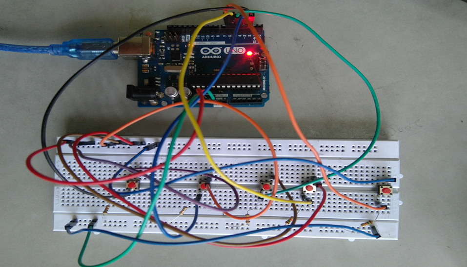
  • Hardware Used: Arduino UNO
  • Components Used: Push buttons, Connecting Wires, Resistances(100k ohm), Breadboard
  • Software Used: Anaconda 2.7.x, Python 2.7.x, Arduino IDE
  • Modules Used: Serial, SQLite, Tkinter, tkMessageBox

WORKING

  • The user has to enter his/her ID in the system.
  • After verifying the user ID, the system will show a message that whether a user is eligible to vote or not after checking his/her details stored in the system.
  • A message will be displayed accordingly. The user will then have to press the button against which the name of the candidate is written and whom he/she wants to vote.
  • The votes hence are stored in the database and the results will be announced accordingly.

FUTURE SCOPE OF THE PROJECT

My project “e-VOTING SYSTEM” will be a great help in conducting voting at various organizations. So the modifications that can be done in our project is to add one major change which can be done in this project is to add the data of the voters. This will result in the total identification of the voter.

CONCLUSION

From this E-voting Machine project, we can conclude that this program is very useful in conducting the voting procedures smoothly. It provides easy methods to analyze the voting result. It helps in conducting faster, more secure, and more efficient voting. The program can be used per the norms of the voting requirements.

Download the complete project code, report, and PPT on E-voting Machine using Python and Arduino.

Accident Avoidance Using IBS and AOCS Major Project

Accidents are increasing at a higher pace and are most common if driving is inadequate. Driver drowsiness is considered an important factor in vehicle accidents, Over Speed can also be considered as another important factor for vehicle accidents.

The main objective of this project is to develop a system for automatic speed control and accident avoidance using eye blink and ultrasonic sensors to keep vehicle secure.

It includes an intelligent braking system in which, whenever any obstacle comes in front of a running vehicle the ultrasonic sensor detects the obstacle at a distance of 4m away from it and sends a signal to embedded board or microcontroller.

And if the driver is drowsy or about to sleep, then the eye blink sensor detects the eye blink and if eyes are closed for more than 30 seconds, the vehicle stops automatically.

Apart from these, the safety of the vehicle can also be ensured by introducing A.O.C.S (Automatic Over Speed Control System). It basically controls the speed of the vehicle by continuously checking it through sensors which sends the signal to the microcontroller.

Whenever the speed is increased above the predefined critical speed, the microcontroller through its logical circuits sends the signals to the actuators via its output pins. The actuators apply necessary force on the brakes and reduce the speed to its safe value.

The sensor used in this system is an optical type infrared sensor and the actuators are stepper motors to which the output of the microcontroller is connected.

Patient Health Monitoring System using Raspberry Pi

PATIENT HEALTH MONITORING SYSTEM

  • This system puts forward a smart patient health tracking system that uses sensors to track patient health. It will be using temperature, blood pressure and heartbeat sensors to keep track of patient health.
  • This system automatically alerts the doctor about the patient’s status through IOT, if it detects any abrupt changes in patient heartbeat or body temperature or BP, it will alert the doctor by sending an emergency message or signal. The information of the patients health is stored on the cloud. The cloud is used for analyzing the patient’s health, to generate weekly and monthly reports and for continuous health monitoring of the patient’s.
  • The system proposes DIET PLAN for the patients according to the readings in the respective parameters which can be viewed by the user/doctor.
  • The doctor can monitor the patient’s health from anywhere.
  • An LCD display will be connected to the raspberry pi for the patients to view their health status live.

The project is Patient health monitoring system using Raspberry Pi.
I need your help to complete this project.

Project Details :
SMART PATIENT HEALTH MONITORING
Our system puts forward a smart patient health tracking system that uses Sensors to track patient health and uses internet to inform their loved ones or concerned doctor in case of any issues. Our system uses temperature, blood pressure and heartbeat sensing to keep track of patient health. The sensors are connected to a microcontroller (raspberry pi) to track the status which is in turn interfaced to an lcd display as well as wifi connection in order to transmit alerts. If system detects any abrupt changes in patient heartbeat or body temperature or BP, the system automatically alerts the Doctor about the patients status over IOT and also shows details of heartbeat, BP and temperature of patient live over the cloud . Thus IOT based patient health tracking system effectively uses internet to monitor patient health stats and save lives on time.

Real Time Hand Gesture Recognition for Computer Interaction

ABSTRACT

The Real Time Hand Gesture Recognition system presented, uses only a webcam and algorithms which are developed using OpenCV computer vision, image and the video processing algorithms.

Existing Work:

The Existing work carried was done a PC based MATLAB software, where it has readily available all the algorithms and such system is not used to full extent in embedded side.

Proposed Work:

Proposed Real Time Hand Gesture Recognition for Computer Interaction work will be carried out on Linux based single board computer with ARM 11 architecture. This board will be ported with Raspbian Operation System and OpenCV Image processing Library. Using which will design an algorithm such that the system will identify the finger tips and count them how many fingers have been displayed.

BLOCK DIAGRAM


Hardware:

ARM11, USB Camera, Power supply.

Software:

OS: Embedded Linux, Language: C/ C++, IDE: Qt Creator, Opencv.

Applications:

Computer Interaction, Gesture recognition based control

Advantages:

• Elimination of external hardware like mouse
• Easy to access and control appliances using gestures.

Low Cost Intelligent Wheelchair Embedded Project

Design and Implementation of Low-Cost Intelligent Wheelchair

The main aim of this project is to design of low-cost intelligent wheelchair. This chair is designed for physically disabled persons.

It designed to control devices and to ask others their minimum basic needs like water, food etc. wheelchair movement is controlled by using MEMS sensor which attached to their hands; based on hand movement the direction wheelchair is changed.

If the hand moves towards right wheelchair move right direction if hand moves towards left it moves towards left. The movement of the wheelchair is done by using motors connected to the controller through driver IC.

To wheel chair two modes (Mode0, Mode1) particular mode can be selected by using push button. Keys are used to control the devices when it is one mode and in same way same keys are used to tell his basic requirements through voice using APR9600 voice IC.

Devices are connected to controller through relays. The communication between wheel chair and devices controlling board is done by using RF technology. If RF communication is used we require RF transmitter connected to wheel chair and RF receiver connected to devices to control.

The system uses a compact circuitry built around AT89S52 microcontroller Programs are developed in Embedded C. Flash magic is used for loading programs into Microcontroller.

BLOCK DIAGRAM:

WHEELCHAIR:

DEVICES CONTROLLING BOARD:

Temperature Monitoring Multi Bedded Hospital

ABSTRACT

This is a PC based temperature monitoring System using Zigbee communication. In this Temperature Monitoring Multi Bedded Hospital project, four temperature sensors in multiplexing mode are connected to the Atmega16 microcontroller which has eight channel in built ADC.

The temperature values of all the sensors are sent serially by the Atmega16 micro controller through Max 232 to the ZigBee trans-receiver module which then transmits this data wirelessly. The control room has another ZigBee module to receive this data which is connected to the communication port of the PC.

A Software “DAQ System” loaded on the PC takes these values and show them on its front panel, and also logs them to the data base “daq.mdb” One can set by the interactive way some parameters like set point i.e. the high limit on the computer screen. High limit and low limits are for alarm. When the temperature goes above high limit the alarm will be turned on.

The Temperature Monitoring application consists of microcontroller Atmega16, the temperature sensor (LM335), Current Driver ULN 2003 and Max232 for the serial interface. The on chip firmware controls reading of the ADC converter, receives commands from PC and sends the reading to PC.

We use the LM335 temperature sensor. The chip produces an output signal that is proportional to the Celsius temperature scale.

SOFTWARE :

• AVR STUDIO
• EMBEDDED C
• UCFLASH

HARDWARE :

• ATMEGA16 Microcontroller
• LM35 Temperature Sensor
• ULN2003 Current Driver
• Buzzer
• Max232 Interface

BLOCK DIAGRAM

Electronic Eye Embedded System Project

With the increase of robberies, people are acting smarter to cheat the concerned security. To avoid this, we need security system and this can be fulfilled by this project “Electronic Eye”.

This project is based on Intel’s 8051 families of the microcontroller. This Embedded system project is based on highly sensitive PIR Sensor. When you are away for your house and if anyone tries to enter the house by any means the device generates an alarm signal, that is enough to chase the thief, Where the thief will run away so your house is protected. So that you understand that something is wrong at your house, you can immediately call up your neighbor to look after your house.

When you are away for your house and if anyone tries to enter the house by any means the Electronic Eye device generates an alarm signal, that is enough to chase the thief, Where the thief will run away so your house is protected. So that you understand that something is wrong at your house, you can immediately call up your neighbor to look after your house.

Technology & Components Used:

1. Embedded C
2. Keil compiler
3. UC-Flash
4. Microcontroller
5. Power supply

Block diagram:

Schematic diagram


Braille language learning kit for visually impaired people

There are large amount blind people in the world today and of them, many are unknown to specially developed language braille. Braille language is made up only 6 dots arranged in 3 rows and 2 columns. So there are total 64 combinations. In which 26 are used for alphabet and numbers.

We are making a mechanical plus embedded system which can represent Braille letters in some form. We can revolutionize the total process of learning braille.

The main motto of this Braille language learning kit system is to replace old fashioned “braille” books having tremendous weight.

Visually impaired people generally use heavy books having text on one side only. They use all their fingers to read. So to introduce them this language, the trainer takes continuous effort. We are planning to make pc software which can be used as personal trainer. Which contains some dedicated module for teaching braille.

We are planning to make pc software which can be used as personal trainer. Which contains some dedicated module for teaching braille.

Braille language learning kit Embedded system is developed using arm processor kit. Also, this system is the combination of electronics and mechanical system. So as to develop the mechanical system we are planning to use the combination of DC motors plus some platform.

Online Handwriting Recognition using Motion Sensor based Pen Device

With the advances in current technology, we see a rapid increase in availability, but also a demand for intuitive interaction between man and computer. While recognizing has been developed graphically based on the vision, it has some limitations, such as running a camera in one place, with the advantage of using motion sensors to develop a portable device.

Combining the rapid development of man-computer technology and the growth of portable devices, a handheld device integrated with motion sensors has been proposed to recognize handwriting by capturing interaction writing paths.

The goal of this Handwriting Recognition project is to develop a portable pen movement base for the online reorganization of letters or handwritten sensor numbers. Users can use this pen to write letters or numbers in the air.

Signs generated by hand movements are generated by in-device and transmitted to the PC for processing and additional signal recognition via a wireless motion sensor module. A handwriting recognition algorithm will be developed for recognition signals using measured by the sensor.

A portable device will be developed base pen with motion sensors (triassic accelerometer, compass and gyroscope), a microcontroller and a wireless transceiver. This pen-based motion sensor can be used to enter numbers or letters in a free space at normal speed.

The sensors are used to detect hand movements. The microcontroller collects the hand motion sensors and wireless transmitters signals in the main PC processor for processing and recognizing the additional signal via a wireless transceiver.

A Handwrite Algorithm (DTW) recognition is implemented to perform handwriting recognition using the signals detected by the integrated sensors in the device.

Block- diagram:

Bus Tracking System using GSM Module Project

Bus Tracking System:

Using  GSM Module and Microcontroller we are designing and implementing a time saving system for daily BUS commuters, which will give the information about the present position of BUS whenever subscribed by the subscriber for a particular BUS, which will have its unique code.

Scope of the Project:

  • Bus Tracking System can be implemented in government, company, college & private buses.
  • Can also be implemented using GPS system.
  • Ring can be developed for blind people to get the status of bus.

Brief Description:

In the Bus Tracking System project, an IR transmitter is placed in bus & IR RECEIVER unit is placed at bus stop. Whenever bus reaches bus stop our unit comes to know which bus has been arrived. The transmitter present in the bus transmits a certain code using RC5 protocol. Carrier frequency for RC5 protocol is 36 kHz.

IR receiver which is present on bus-stop detects the IR signals and gives the coded data to the microcontroller for decoding purpose.  Microcontroller is controlling block of the system. After decoding this code, which bus has arrived is decided.   The acknowledgement is given to the system user through SMS. This SMS is send whenever bus is arrived.  The subscriber numbers to whom the message has to be send is stored in the EEPROM, which is the memory element used over here.

The 89s52 microcontroller communicates with EEPROM using I2C protocol. Whenever a message is to send to the subscriber for the subscribed bus controller  fetches those subscribed numbers & then send the message through GSM module. Microcontroller and GSM module are interfaced through MAX 232. . MAX232 is a device which converts TTL voltage logic levels to RS232 & vice versa.

The GSM module sends SMS to the subscriber which is mentioned in EEPROM through AT commands.  AT commands are used to send SMS from GSM module. LCD is used to display which bus has arrived.

The block diagram:

HARDWARE REQUIREMENTS:

Sr. No. Components Specifications Quantity
1 Microcontroller 89s52 1
2 MAX 232 IC DIP 16 PIN 1
3 GSM Module SIM 300 1
4 EEPROM CAT 24WC 08 8KKBit Serial CMOS 1
5 IR Transmitter Phillips RC-5 (Carrier Freq 36 KHz) 1
6 IR Receiver TSOP 1840(fo-40khz) 1