
This Obstacle Avoidance Voice Controlled Robotic Vehicle Project work is mainly based on Arduino, Motor driver, and Bluetooth module. Arduino is an open-source prototyping platform that is based on easy-to-use hardware and software. Arduino makes use of an ATmega328 microcontroller.
Robotics has become a major part of our day-to-day life and also it plays a vital role in the development of new technology in the engineering field. This is a simple type of remote control car, where the ordinary microcontroller has been replaced by Arduino and the IR sensors have been replaced by the Bluetooth module.
The remote device to control this device can be any android or IOS mobile phone. And in this, we have also included the ultrasonic sensor which detects any obstacle present in front if any it stops the car. This project can be made used on a large scale for real-time vehicles.

This project is controlling cars not by using sensors or transmitters but by using Bluetooth which is a very simple medium of communication in the present day. The remote device which controls this project is an android device that has an inbuilt Bluetooth module. Through Bluetooth, we can connect two devices.
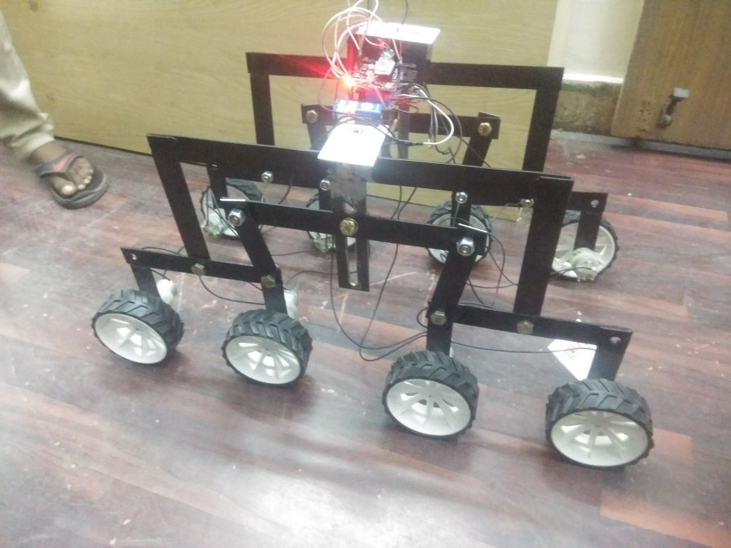
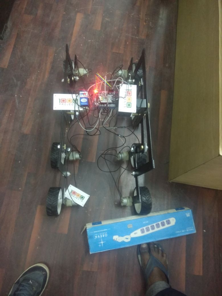
Here we have inserted a Bluetooth module that gets connected to the phone‘s Bluetooth, which allows us to communicate and allows to take control over it. The main control of the car is played by the Arduino UNO which is the micro-controller ATMEGA32. Arduino has played a major role in the robotic section and it had made it easier to convert digital and analog signals to physical movements.
This project is Bluetooth-based because it gives us a wider range of control and more efficiency. It also gives us the advantage of changing the remote anytime, so that we can use any android device including phones, tablets, and computers. Physical barriers like walls and doors do not affect controlling the car. We have also included the ultrasonic sensor which helps the bot to stop automatically when an obstacle is present before it. An obstacle detector is added to protect the system from obstacles on the way by using an ultrasonic sensor that is mounted on the servo motor.
The voice-controlling commands are successfully transmitted via Bluetooth technology and on reception; the desired operations successfully take place. This project reduces human efforts in places or situations where human interventions are difficult. Such systems can be brought into use in places such as industries, military, and defense, research purposes, etc.
Hardware components to implement this project:
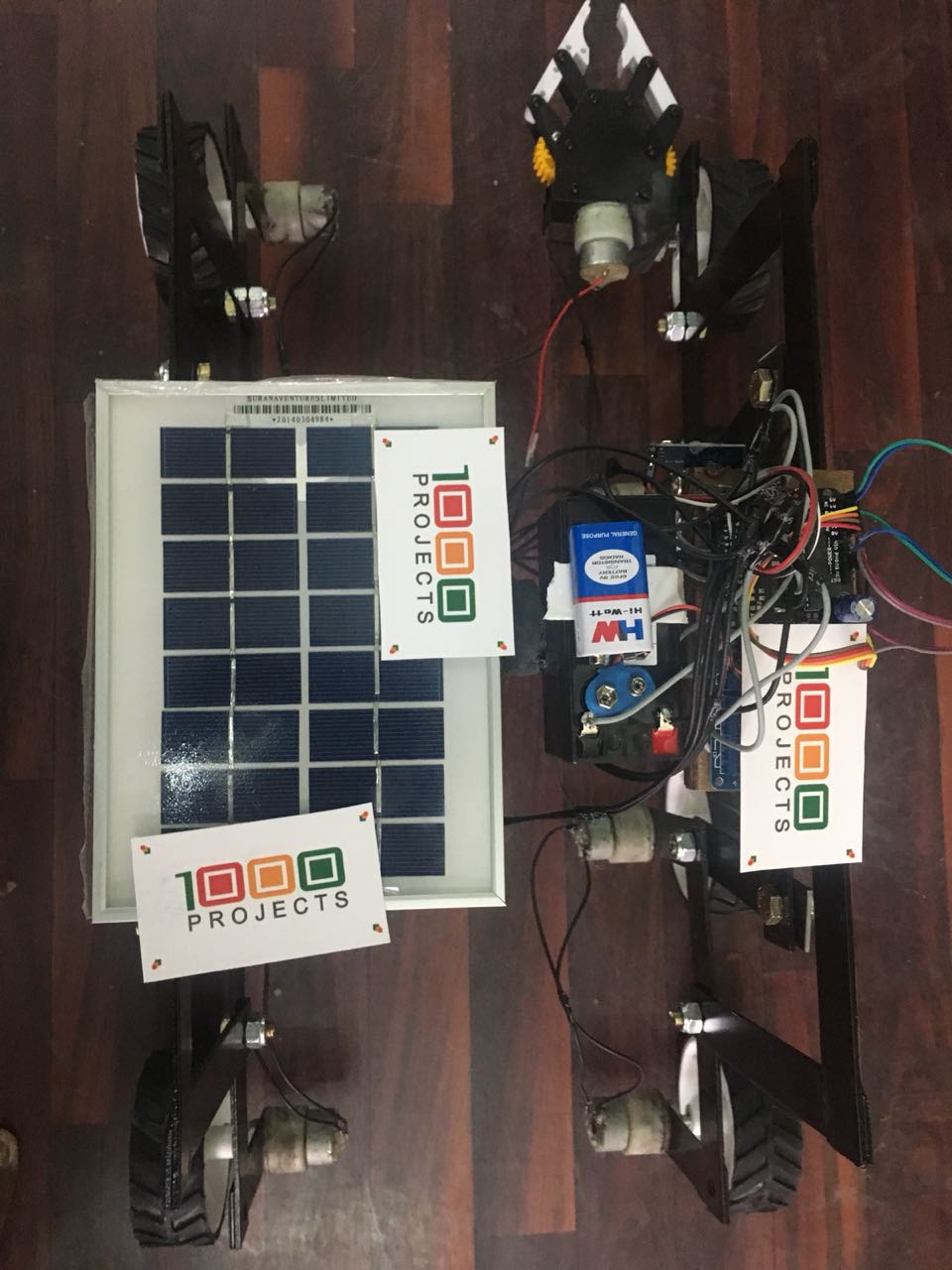
- Arduino UNO
- Motor shield
- Ultrasonic Sensor
- Bluetooth Module (HC-05)
- Servo Motor
- Jumper Wires
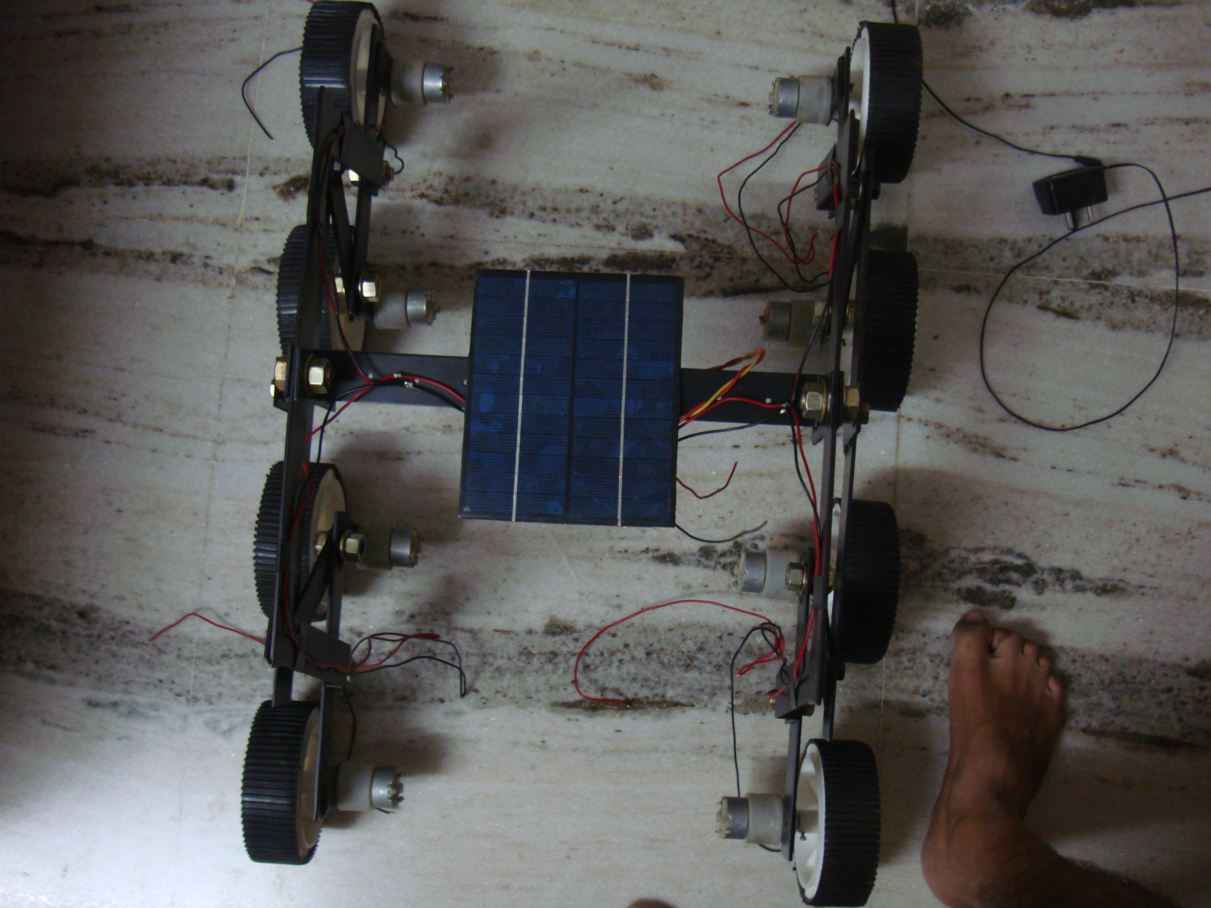
- Bo Motor 300 rpm
- Car Kit
Download the complete OBSTACLE AVOIDANCE VOICE CONTROLLED ROBOT Final Year ECE Project code & Report.


