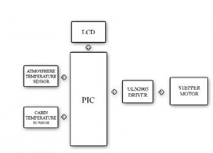
This project entitled “AUTOMATIC WEATHER CONTROL OF CAR AIR-CONDITIONING SYSTEM”, is designed and implemented using PIC microcontroller, an IC manufactured by Microchip Corporation.
In this project, according to the external and cabin temperature, the hot air from the heater and cold air from the Air Conditioner is mixed automatically and hence easy and efficient Air Conditioning is achieved. This mechanism involves the control of the duct mechanism present in the Air Conditioner setup by using a stepper motor.
The advantages of our project are
- Economical
- Easy Installation
- Compact
DISCUSSION OF RESULTS
We have presented a method for making the air-conditioning system in a car, run efficiently and automatically. Our Automatic weather control system has provided a simpler way of air-condition control.
FUTURE WORK
This efficient control mechanism can be further developed to control the Air Conditioner throw by controlling the blower motor.
The vent mechanism in the car Air Conditioner can also be automated by this efficient method.
|
TABLE OF CONTENTS
|
|
TITLE |
| ACKNOWLEDGEMENT |
| ABSTRACT |
| LIST OF FIGURES |
| LIST OF TABLES |
| INTRODUCTION |
| 1.1 Synopsis |
| INTRODUCTION TO EMBEDDED SYSTEM |
| 2.1 Embedded System Tools
2.1.1 Microprocessor 2.1.2 Microcontroller 2.1.3 Advantages Of Using Microcontroller Over Microprocessor |
| 2.2 Design of Embedded Systems |
| MICRO CONTROLLER PIC 16F877A |
| 3.1 General |
| 3.2 Pin Diagram of PIC 16F874A/877A |
| 3.3 Applications |
| 3.4 Ports
3.4.1 PORTB and TRISB 2.1.2 PORTA and TRISA |
| 3.5 Functional Block Diagram of PIC 16F877A
|
| SOFTWARE DESCRIPTION |
| 4.1 Software Tools
4.1.1 MPLAB Integration 4.1.2 Introduction to Embedded ‘C’: 4.1.3 Embedded C Compiler
|
| 4.2 Embedded Development Environment
|
| 4.3 Embedded System Tools
4.3.1 Assembler 4.3.2 Simulator 4.3.3 UMPS 4.3.3.1 UMPS Key Features 4.3.4 Compiler 4.3.4.1 Phases Of Compiler |
| PROJECT DESCRIPTION |
| 5.1 Block Diagram |
| 5.2 Circuit Diagram
5.2.1 Hardware Circuit Diagram Explanation |
| 5.3 Components and its Function:
5.3.1 Resistors 5.3.2 Capacitor |
5.4. Power Supply5.4.1 Power Supply Layout 5.4.2 General 5.4.3 IC Voltage Regulators 5.4.4 Three-Terminal Voltage Regulators 5.4.5 Fixed Positive Voltage Regulators |
| 5.5 Printed Circuit Board
5.5.1 Introduction 5.5.1.1 Advantages of PCB 5.5.1.2 Types of PCB 5.5.1.3 Do’s and Don’ts 5.5.1.4 Tips to Simplify PCB Manufacturing 5.5.2 PCB Layout |
| 5.6 Liquid Crystal Display:
5.6.1 Liquid Crystal and Other Display 5.6.1.1 General 5.6.1.2 Filament Display 5.6.1.3 Gas Discharge Display 5.6.1.4 Fluorescent Vacuum Display 5.6.2 Interfacing withHitachi44780 |
| 5.7 LM35 Precision Centigrade Temperature Sensors
5.7.1 General Description 5.7.2 Features 5.7.3 Absolute Maximum Ratings 5.7.4 Connection Diagrams 5.7.5 Electrical Characteristics 5.7.6 Typical Performance Characteristics 5.7.7 Temperature Rise of LM35 Due to Self-Heating 5.7.8 Applications |
| 5.8 Stepper Motor Description |
| 5.9 High-Voltage, High-CurrentDarlingtonArrays |
| CONCLUSION |
| 3.1 Discussion of Results
3.2 Future Work |
|
APPENDIX-I Sample Coding |
| APPENDIX-II
Abbreviations |
| REFERENCES |

