Network Traffic Routing Over Neural Network

Project Title: NETWORK TRAFFIC ROUTING OVER NURAL NETWORK

Abstract: For routing the information over the network, a number of routing techniques are available. To transfer the data efficiently acroos the network, a rotuing algorithm which is the best should be selected. No discussion was done on the selection of best routing algorithm and for the given subnet configuration, making a choice of best routing algorithm is only defined by the entire problem.

Calculating the efficiency of routing algorithm which the user selects and deciding the best one among them is the main aim of the project.

Efficiency of Subnet:

The folowing formula can be used for calculating the efficiency of any routing algorithm

Efficiency= i / n
where i is the efficiency of router and n is the number of routers in the subnet 

Main aim: The NETWORK TRAFFIC ROUTING OVER NURAL NETWORK has the following objectives:

  1. There should be a proper display of topology of the desired subnet with the designated routers to it and the appropriate links along with proper computer images.
  2. Congestion table should be should be displayed with appropriate congestion links.
  3. Statistics of any router like efficiency, average size of the packet should be displayed as per the requirement.
  4. When ever the congestion table is clicked, statistics like propagation delay of the link, buffers filled are displayed.
  5. When ever the router is crashed, a provision should be provided where the router crash is handled. 
  6.  When ever a link is down, there should be proper handle of that and thus enhancing the routing even if a link is down. 
  7. The statistics for the router and the link are to be calculated for every 500 m sec. 
  8. Congestion table should be re constructed. 
  9. A speed controller should be provided for routing.

Both the quantitative and qualitative methods can be used to measure the performace of the network routing over different topologies. Statistical analysis of the data transfer can be estimated with these methods

Software Requirements:

Two desktop systems with printer with windows xp operating system
– Internet connection
– Java JDK software 

LIST OF CONTENTS

  1. Introduction
  2. Literature Review

2.1 Research problem

2.2 Research methods

2.3 Project purpose

2.4 Project scope

2.5 Project outline

2.6 Project definition

2.7 Existing system and problems

2.8 Proposed system

  1. Analysis

3.1 Network topologies

3.1.1     Bus topology

3.1.2     Ring topology

3.1.3     Star topology

3.1.4     Tree topology

3.1.5     Mesh topology

3.2 Routing

3.2.1     Unicast routing

3.2.2     Broadcast routing

3.2.3     Multicast routing

3.2.4     Anycast routing

3.3 Routing table

3.3.1     Network route

3.3.2     Host route

3.3.3     Default route

3.3.4     Static routing

3.3.5     Dynamic routing

3.4 Router

3.4.1     Control plane

3.4.2     Forwarding plane

3.5 Packet

3.5.1     Packet framing

3.5.2     User data

3.6 Routing protocols

3.7 Factors to decide best path

3.7.1     Path length

3.7.2     Reliability

3.7.3     Delay

3.7.4     Band width

3.7.5     Load

3.7.6     Communication cost

3.8 Choices in routing

3.8.1     Static and dynamic routing

3.8.2     Single path verses multiple path

3.8.3     Flat verses hierarchical

3.8.4     Router intelligent and host intelligent

3.8.5     Inter domain and intra domain

3.8.6     Centralised verses de-centralised

3.9  Routing algorithms

3.9.1     Flooding

3.9.2     Hot potato routing

3.9.3     Source routing

3.9.4     Distance vector

3.10       Routing information protocol

3.11       Link state algorithm

3.12       Subnet efficiency

  1. Design

4.1 Design goals

4.2 Router

4.3 Link

4.4 Routing algorithm

4.5 Names and objectives

4.5.1 Brief

4.6 Client application overview

4.7 Network communication design

4.8 Server application overview

  1. Implementation

5.1 Structure of the server application

5.2  Structure of the client application

5.3 Software requirements

5.4 Java tools

5.5 User guide

5.6 Operating

  1. Testing and evaluation

6.1 Online response

6.2 Stress testing

6.3 Sample outputs

  1. Conclusion
  2. Future scope
  3. References

Chat Server Project Report in Java

Introduction to Chat Server Project:

Chat server is an online system created for the community of people to interact with one another on the Internet. This system provides solution to most of the shortcomings of the traditional system. The teachers, students and the firm are profited evenly by the suggested system. The system preserves a great amount of time and effort too, for both. A new software has been introduced for chatting, which is called Chat Server. This software plays a pivotal role in decreasing the interaction gap among the various people in a college, so it can be termed as very significant for the college.

This system includes four stages of interaction or three modules:

  • Administrator level: Administrator level enables only the administrator to log in to it and  make required alterations in database and other significant fields of the system, by going to this level. He has the authority to accept or decline the request of a newly registered user.
  • Staff level: Staff level is meant for the employees functioning at different divisions and departments. The employees will log in employing the user ID and password.
  • Student level: Student level enables the student to login in to the site from any place. He can get to know the position of other chatters by login and can chat online and offline and also send feedback to his teachers.
  • Parent level: Parent level enables the parent to chat with his ward as well as the teachers.

Hardware Requirements:

An Intel Pentium class, 600 MHz or higher, a RAM of 256 MB, a Free hard disk space of 600 MB, a super VGA monitor and a CD ROM drive of 52X is required.

Software Requirements:

An Operating System of Windows 2000 Advanced Server Windows XP, client side-HTML and server side- JSP, Servlets are required.

Download  Chat Server Project Report in Java .

Online Recruitment Java Project Report

Introduction to Online Recruitment Java Project:

The IRECRUIT is totally automated recruiting system of an organization that reduces the manhandling and tedious procedure of screening of an thousands of applications. The computerizing features allows the recruiter to screen the applications in less processing time, less effort, fast response, flexibility, good performance and measurable. 

The scope of the project is to record the information of the candidate and manage the huge data of all applicants that includes Job postings, applicants, companies, resumes and the people. The web page allows us to retrieve information such as Job details, Resume reports and Applicant details and also to create information such as Use reports, Job reports, Transaction reports, usage reports and skill reports. The candidate can search for the job by logging in. The HR application allows HR personnel to shortlist the applicants and makes selection criteria. 

The IRECRUIT system possesses four major modules.

  1. Candidate or Aspirant module.
  2. Employee module.
  3. Recruiter module.
  4. Administrator module. 
  • Candidate module allows candidate to post resume, search job and manage profile. 
  • Employee module has options for the HR recruiter to find all candidates suitable and can post new job. 
  • The administrator module allows the recruiter or administrator to manage all the details regarding companies, people, and job postings. 

Software requirements:

Operating system: Windows 2000 or higher

Jboss 3.3, J2SDK 1.4, Internet Explorer 5.0 or Mozilla 

Hardware required:

Pentium III Processor

RAM 256 MB

Download  Online Recruitment Java Project Report  .

IT Enabled Academia Project

OBJECTIVE: 

The product states to automate the regular teaching-learning integrated activities which make an academic administrator to observe and regulate the ongoing matter. This includes schedule preparation for possible resources such as Programmers, courses, subjects, faculties, and lecture room or lab preferences. The IT Enabled Academia would combined with Uploading lecture notes or assignments, regular attendance, student feedback report, updated exam marks and students/faculty portfolio’s. 

Current system for Academia 

1. Current system is handled manually which possesses possibility of errors. 

2. Current system is unable to do enrolment of students by itself. 

3. Regular attendance of faculties cannot be provided in a single display, it  has to be created manually. 

4. The system is not able to present feedback from each student and even .Unable to guide student personally.  

Proposed System 

The improved system automates the whole process through Database integration approach. 

The Proposed system creates schedule for all teachers to take their classes by differentiating the days, time and class rooms which does not interrupt to other teacher.

 Faculty has option to plan their lecture and topic, display their course contents which student can easily explored. 

The students can post their feedback and suggestions to the faculty which makes academia more clear for improvements and guidance to students.

Download  IT Enabled Academia Project .

Remote Method Invocation in Java

The Remote method invocation (RMI) design has to be developed in distributed Java programs consists of similar syntax and semantics that are applicable in non- distributed programs. One has to observe or learn the Java classes and objects in single Java virtual machine (JVM) and then go for the Java classes and objects to run on distributed Java virtual machine (Multiple MVM). 

RMI architecture is about the functions of objects, to keep memory, the limits, and remote operating procedures.

To design RMI system, the steps required:

  1. To develop interface Java code to write and compile.
  2. To implement classes Java code to write and compile.
  3. To create Stub and Skeleton class files from implemented classes
  4.  RMI Client program to be developed by Java code
  5. The RMI system to be install and run 

Java RMI Architecture 

The RMI Architecture designing is combined feature of Java programming language and the local object model developed with   Java distributed object model. The RMI architects developed successfully a safe and rich of Java architecture for the distributed computing. 

The theory of RMI architecture is relied on two major concepts, the definition of behavior and the implementation of the particular behavior. It requires code to define behavior separately the implement of behavior that can run separate JVM’s. 

The distributed system segregates the system by clients to know the definition and servers should be aimed in giving service. 

Mainly the RMI’s remote service is developed by applying the Java interface. How to apply the remote service has needed to code in a class. The RMI knowledge requires to memorize the interface define behavior and classes define implementation. 

So RMI system includes the Client Program for Interface and Server Program to implement. The RMI support for running two classes on the same interface which is included first class to apply the behavior and that runs on server and second class is remote service consists of proxy runs on client. The client program is used to put method calls on proxy objects, for which RMI instructs the remote JVM for implementation. The return values of implementation by remote JVM goes to client’s program via proxy service. The RMI uses network stack and TCP/IP for communications between JVM’s.

  Download  Remote Method Invocation in Java .

Project Report on Online Billing System in Java

Introduction to  Online Billing System in Java:

The record keeping and reporting is the key of successful transactions which definitely consists of user friendly interface with easy and common application. The objective to develop the application is based on the easy way of getting yellow page information. The application can be used easily for record keeping and reporting. The application can be installed on desktop or operated via client/server architecture. 

The system is easy to use with simple knowledge of computer. The applied principles in this system are instinctive and depend on running application at user interface. 

The following steps are included in the developing of an application.

  1. Information collection
  2. Design
  3. Coding and assigning
  4. Testing
  5. Applying the application at User end 

Programming Language were used in developing this application:  JAVA with JS, Javascipt, HTML. Database application used MS Access. 

Hardware was used: RAM 64 MB and 2 GB hard disk. 

Operating Systems: Windows 95 & higher version. 

Architecture: The modules is divided into

  • Login
  • Create User
  • Add entry
  • Erase Entry
  • Modify Entry- 1. Search name, 2. By mobile number.

The online Billing application is providing with efficient GUI to the user and can be installed in other systems easily.

  Download  Project Report on Online Billing System in Java.

Virtual Medical Home Project Report

Introduction to Virtual Medical Home Project:

This application is done by rational unified process. This RUP unifies the generic process models supports the good design with three view namely dynamic, static and practice model. The RUP also hold four phases like inception, elaboration, construction and transition.

The need of the virtual medical home is to provide the health care to the people mainly in the villages via internet where the hospitals are few or nil. Four elements are included to implement VMH namely patient, internet, webcam, doctors and kiosk manager. To use this service we need markup languages, http/https protocols for communication interface, database and java.

In ancient time there is only net used to store the patient records who used to go to the hospitals directly but in this model we have included webcam software kiosk manager to treat the patient by sitting in their home itself with the help of database 2,RAD, WASCE, rational software model technologies. In this the patients records are maintained as authorized used.

Work Flow: The user, doctor and the kiosk manager need to register their details to get the login ids. These id are sent to administration for reification now the user is provided with kiosk id, password and user id. When the patient feel to see the doctors. Patient need to enter their user name and password to get the appointment from the desired doctor to know whether the doctor is available or not if the doctor is in available the patient request will be sent to the doctor id and he gives the appointment time.

At the appointment time the patient and the doctors interact through the java application and GUI interface. The doctor can also diagnose the patient through webcam by generating the complaint id. This id will be sent to the admin for the record and reification and the admin replies to the user according to the reification of the compliant. The prescription also sent to the patient though id.

Download Virtual Medical Home Project Report software requirement specifications .

Final Year CSE Computer Network Project Report

Introduction to Computer Network Project Topic:

It is a bunch of computers that are adjoined by photo-electric boundary or other act of transporting of many sketches and machinery with the by interchanging data or information for users.

Networks may be classified according to a wide variety of characteristics. This article provides a general overview of types and categories and also shows the basic components of a network.

Networks are built with adjoin of computer hardware and software.

Types of Computer Network:-

  1. LAN (LOCAL AREA NETWORK)
  2. WAN (WIDE AREA NETWORK)
  3. MAN (METROPOLITAN AREA NETWORK)
  4. PAN (PERSONAL AREA NETWORK)
  5. VPN (VIRTUAL PRIVATE NETWORK)
  6. CAN (CAMPUS AREA NETWORK)
  7. GAN(GLOBAL AREA NETWORK)
  8. SAN (STORAGE AREA NETWORK) 

Some Basic Components are:-

  1. These networks are formulated on basic hardware building blocks by linking nodes of network, such as (NICs), Routers etc…
  2. In addition, some method of connecting these building blocks is required, usually in the form of galvanic cable.
  3.  Less random are microwave links or optical cable (“optical fiber”). 

Some of the basic components required for adjoining the network nodes: –

  1.    NETWORK INTERFACE CARD.
  2.    REPEATERS.
  3.    NETWORK HUB.
  4.    NETWORK BRIDGE.
  5.    NETWORK SWITCH.
  6.    ROUTER.

Bridges are sub divided in three types:-

  1. Local bridges: It connects to LAN.
  2. Remote bridges: WAN can be developed by this bridge. Link between LANs. Remote bridges, where the adjoining link is less than the end networks, largely have been displaced.
  3. Wireless bridges: It can be used to join LAN or connect to LAN.

Download  Final Year CSE Computer Network Project Report .

Test Cases for Chess Game

Test Case 1:

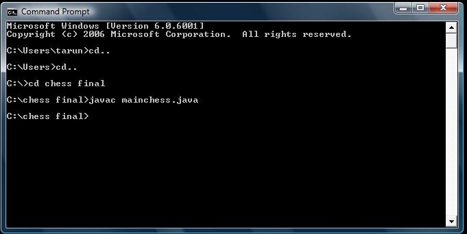
Input given: To compile the program without the errors.

Status: changed

Output: The program is compiled properly without any errors if any errors are occurred it will be displayed below the compilation input, so in this test case there are no errors so the compilation was successful and was preceded to the next step.

Test Case 2:

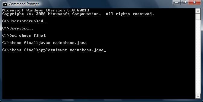
Input given: To execute the applet by giving the command.

Status: applet displayed

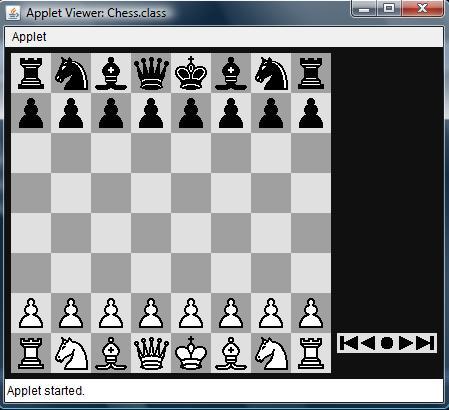
Output: After entering the code for execution of the program the command prompt will automatically pop up an applet which as shown below, if there are any internal errors in the program the applet will not appear.

After entering the command in the command prompt as shown above and executed it will be redirected to the applet which is shown below

Test Case 3:

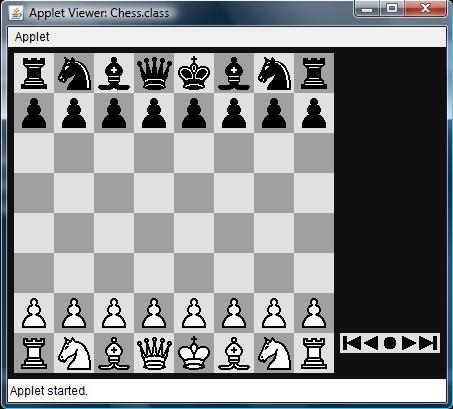
Input given: Check whether all the pieces of the both sides are available or not and also check whether they are properly organised or not.

Status:  Performed

Output: All the pieces are available and fairly organised for both sides which are satisfying the basic rules of the game is shown below.

Before going to play the chess a proper check for the moves of each and every piece is tested and the test cases of them and their results are shown below

Test Case 4:

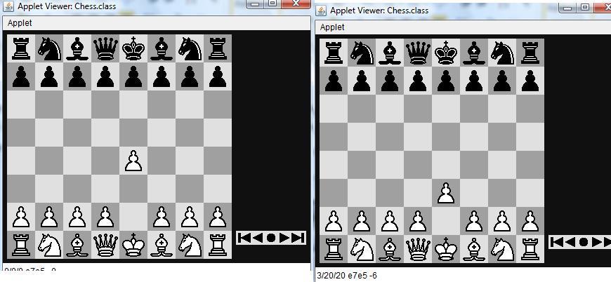
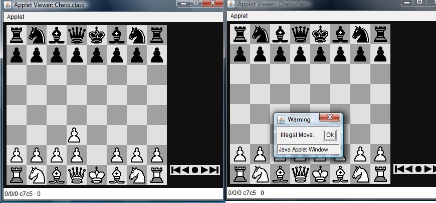
Input: checking the move of the pawn.

Status: Performed

Output: It is satisfying the rules of the game if any other move that is not a valid move of pawn is performed an dialog box will be displayed, the dialog boxes for the test cases are shown below the screen shots for the test cases.

The above screen shots shows the valid moves of the pawn, and if any other moves for the pawn are the dialog box appears as shown below.

Test Case 5:

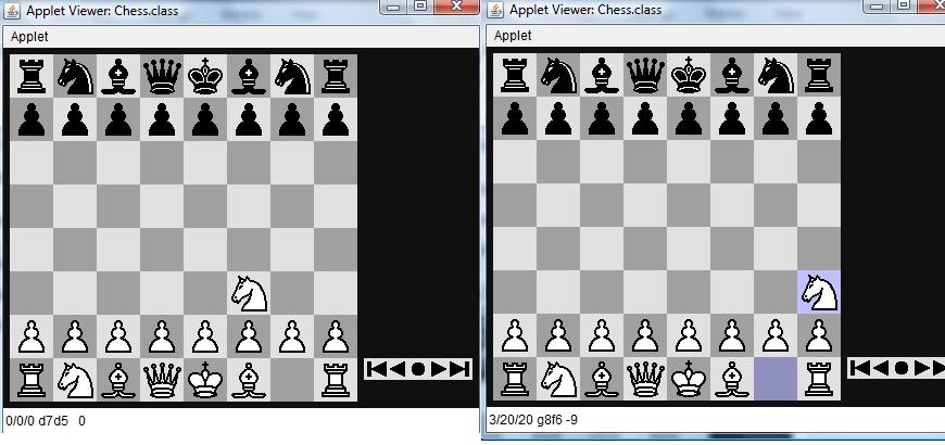
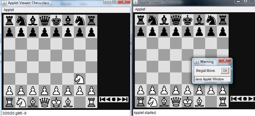
Input: checking the move of the knight.

Status: Performed

Output: It is satisfying the rules of the game if any other move that is not a valid move of Knight is performed an dialog box will be displayed, the dialog boxes for the test cases are shown below the screen shots for the test cases.

The above screen shots shows the valid moves of the Knight, and if any other moves for the Knight are the dialog box appears as shown below

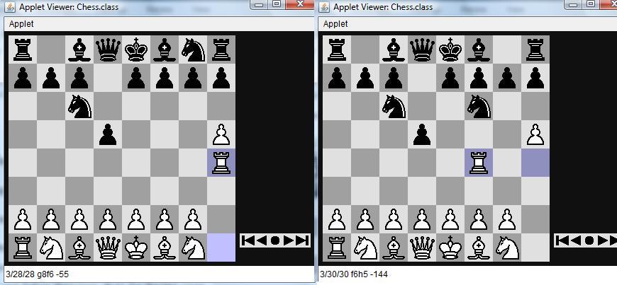
Test Case 6:

Input: checking the move of the Rook.

Status: Performed

Output: It is satisfying the rules of the game if any other move that is not a valid move of Rook is performed an dialog box will be displayed, the dialog boxes for the test cases are shown below the screen shots for the test cases.

The above screen shots shows the valid moves of the Rook, and if any other moves for the Rook are the dialog box appears as shown below

Chess Game Design Java

Design of this chess game is divided in to following modules: 

  1. Board representation
  2. Move representation
  3. Piece representation
  4. Analyzer

Move representation: 

Representing the possible moves is really an important aspect in designing the chess game and this section explains the actual procedure followed to handle all the possible moves in this application. A separate module known as chess engine is designed in this program to handle all the possible moves and a separate module of code is required as the possible moves are really high in a chess game. Move against the human move from the computer side need lot of estimations and eliminations and in there, typical tree search algorithm can be used to search for the best move possible. These moves are mainly decided by the position of the piece on the chess board and few predefined moves are assigned to the piece based on the nature of the piece on the board. A typical switch and case condition loop is used to check the type of piece initially and then based on the case identified the moves are defined. The moves are assigned to these pieces based on the square positions, the corresponding characters assigned to the squares and position of the square on the total board. All the possible conditions are checked for all the pieces with respect to the position of the board initially and later the actual moves against the human moves are done in a separate way. The famous tree search algorithm known as alpha beta pruning algorithm is used to decide the best move for the computers from all the possible moves in front of the computer. To proceed with this algorithm, initially alpha and beta variables are considered and an initial depth is assigned as an integer and then these values are incremented or decremented and compared to follow the tree search process. Moves are represented based on the depth value of the alpha and beta and the kind of piece with respect to this depth position on the chess board. Alpha and beta are used to represent the current square position of the piece that need to be moved and the beta represents the target move and thus from the value of the depth calculated as discussed above, the actual move of the desired piece is decided. Once the best move is decided from all the possible moves, the actual move is shown to the users using the same graphic class of the Java Applet package. All the required action listeners are added to the piece movements and the most common among them are the mouse listeners and the computer always recognizes the moves made by the human player using the mouse action listeners and the moves are compared to the predefined moves saved at the memory with the moves made by the human player and as discussed these moves are identified using the mouse action listeners and even the validity of the moves made by the human player is also checked against many conditions. 

Piece representation: 

The very next once the move representation is done is to represent the graphical user interface of the pieces and the corresponding moves of them on the chess board considered. All the images of the required pieces are taken in the same folder where the coding files are maintained and the reference to them are made using the file path in the design process. All these pieces are placed on the squares of the chess board based on the characters assigned to the squares using the character array as discussed in the board representation section of this document. A separate method is used to represent the pieces on the board and is named as drawFigure and the parameters given to this method are like character for the square assigned, x-axis position and y-axis position. Board design takes care of the square positions and the corresponding square positions are designed with respect to the pieces and their respective placement on the squares. Properties for the pieces are assigned at the chess engine level and the corresponding hash codes are assigned as the constant values with respect to these pieces at the backend of the chess engine design. Few methods are defined these pieces in the form of a separate interface and these methods holds the required properties for the corresponding pieces used across the board. Moment of these pieces is defined with respect to the changing positions of the board and the required attributes are set accordingly in these methods. 

Analyzer: 

Design of the analyzer include the time controls used across the chess game and a detailed coding aspects to the alpha beta pruning algorithm based on the time limits imposed across the chess game. Five different time intervals are considered in this design like 50, 100, 300, 600 and 1800 and the corresponding limitations with respect to the time are given based on the human moves. As discussed in the previous section, the human player moves are captured by the mouse action listeners and the corresponding moves are compared against the time limits set across this design.  Time frame allocated in this design is incremented using exponential functions and if the time limit is reached the corresponding action to be taken by the computer program are also defined in this analyzer module. A minimum time limit is given to the human player during the initial moves and gradually the game process, more time limits is allocated to the player in the middle of the game, as the player need more time to analyze the moves and make the right move. A multi threading program is designed in this case to handle the time limits assigned to the human players.