Global Positioning System B.tech Seminar Topic for ECE Final Year Students

This paper discussed about a special-based global navigation satellite system, Global Positioning System (GPS).  GPS satellites are maintained by United States Government and it can be used by any user around the world with a GPS receiver with some technical limitations.  In order to address and overcome the problem of previous navigation system, the GPS project was evolved in 1973.  During that time GPS was running with 24 satellites.  

Overview:

Global Positioning System (GPS) receiver receives the signals from GPS satellites which are located high above the earth and then calculates its position by clearly timing those signals. Each satellite continually transmits the message with the information included like time of the message transmission, clear orbital information and system health of all GPS satellites.

Many civilian applications uses absolute location, relative movement and time transfer components of a Global positing system. Clock synchronization, Cellular telephony, Geotagging, GPS Tour and Navigation are the most important GPS applications for civilian.  Satellite clock error, Atmospheric error and Receiver clock error are the three sources of errors in GPS.

 Both Ionospheric error and Tropospheric error are parts of atmospheric error.  Space segment, control segment and user segment are three segments consisted by a GPS element. GPS works in microwaves bands. GPS unit have few problems when operate it in rain, forest, jungle, deep canyons, and inside automobiles. Actuation of Gold code helps to demodulate and decode GPS satellite signals. Every GPS continuously broadcasts a navigation message with rate 50 bps. Position calculation, GPS receiver clock and shouting from the stars are the main three basic concepts of GPS.

Conclusions:

Navigation, Target tracking, Missile and projectile guidance are the most important GPS applications for military.  GPS allows military soldiers to find objectives in the dark and coordinate troop and supply movement accordingly.  GPS helps to track ground and air targets. Military aircrafts uses GPS to find targets. GPS allows accurate targeting of military weapons like ICBMs, cruise missiles and precision-guided munitions. 

Download  Global Positioning System B.tech Seminar Topic for ECE Final Year Students .

GSM Based Home Security System Electronics Project for Final Year Students

Introduction to GSM Based Home Security System Electronics Project:

This final year assignment aims to expose students in higher education and technical studies the thoughts & logical processes that need to be urbanized to ensure the student can translate their work into something existing.

This is generally done by the creation of a design or a thought in the field of hardware and software. Also past products are studied to expose their deficiencies and an loom is in use to suggest a resolution which solves the problem.

A safety system encompasses an open standing interruption detector. The sight or has designed sensing element to detect and transmit an intrusion aware of customers.

For the fulfillment of our bachelor degree of engineering in telecommunication stream we select a project. The name of the project is GSM Based Home Security System.

At a time when home security is paramount, automated safety methods are a functional value addition to the modern home.

Vision based security systems can be easily installed, affordable & non- obtrusive. This system aims to detect home intrusion through the use of infrared sensors.

A security system has a open standing intrusion detector. The detector has an in built sensor to detect and broadcast an intrusion alert to customers.

ACKNOWLEDGEMENTS

We would also like to extend our thanks to our H.O.D, Col. R.K. Kapur for his undying faith in us and making us believe in ourselves.

His guidance has been the reason we could complete this project. We are very thankful to all of them.

Download  GSM Based Home Security System Electronics Project for Final Year Students with project Report.

CSE Mini Project Topic on GSM Modem Based SMS Gateway with Project Report

AT COMMANDS are used to design a SMS gateway that can easily communicate with the GSM modem. For proper interaction this system will have a user friendly graphical interface. This in turn will connect with the modem using protocol like HTTP and others.

This system is highly advanced and it is designed with several objectives like to receive and send SMS to mobile device using the computer system.

In this system the computer will be connected to the GSM modem in order to provide smooth efficiency of message transferring. It will also enable to study the AT commands as well as their implementation in GSM modems.

Another aim of this system is to create a GUI based application for receiving and sending messages. It also helps to store messages in the computer’s memory. 

To receive and send message using the GSM modem SMS gateway is the most effective mean and we can send SMS only from those computers that are connected to a GSM mode. At commands are used for this purpose and recently the study and its implementation is done successfully.

Receiving SMS is only possible if we have GSM modem and usually mobile phones do not work on this formula of GSM modem. For more features enhancement is necessary to made in the GUI system. We can now send and receive MMS and also add contact details, etc. 

Related Project on Sending SMS using GSM Modem:

Send and Receive SMS in Asp.Net Using GSM Modem C# Code

AT commands are very useful and with further studies new features can also be developed. Its function ability is outrageous. GUI codes are written in .net using the language of C# that acts as a gateway between GSM and computer modem.

Consideration of timing is important while connecting modem to the computer that uses USB cable, infrared and Bluetooth. Overall, this system is very useful.

Download  CSE Mini Project Topic on GSM Modem Based SMS Gateway with Project Report.

Remote Notice Board Using GSM With SMS Full Project Report

Introduction to Remote Notice Board Using GSM With SMS Project:

The world is shrinking with time because today people from all over the world can easily communicate with one another in just a matter of seconds. Digital techniques of communication are the main brainchild behind this success and with the passage of time these techniques are successfully developing more and more.

Advancement control and communication has become important in all parts of the world. The use of cellular technology – mobile phones have increased drastically in the past years.

The main motto of smart Notice Board Using GSM project is to use mobile phones to receive the message and then send it for display to notice board. This project is designed with the concept of micro-controller and it can be used to control remote notice board.

The heart of the project is P89C52RD2BN. Here the cellular technology is considered for sending message to the notice board. The mobile used is of GSM technology.

The international roaming capability is the main strength of GSM which means it ensures seamless service for the customers. Apart from that it also enable high quality speech, digital experience, call waiting and forwarding services and freedom of using universal mobile phones. SMS is a service of GSM technology by which data can be received and send easily from one handset to another.

The message can consist of alpha numerical combination, words and numbers. SMS service is one of the widest using techniques and it is meant especially for those who have hearing or speech problems. 

The best part is that if you are outside the coverage of the GSM area then the SMS will be stored for you and once you enter the coverage area you will receive it then and there. This will also help you to be aware about the security system of your office and home.

Download  Remote Notice Board Using GSM With SMS Full Project Report.

GSM Technology Project Report

Introduction to GSM Technology Project:

GSM subscriber telephony services:

Under this, the services are ability to make and receive calls to fixed and mobile subscribers all over the world, DTMF, emergency calls, FAX, SMS, cell broadcast.

CME 20 in GSM supports some supplementary services which can compliment and modify both tele services and bearer.

Call forwarding includes call forwarding on MS not reachable, call forwarding on MS busy, call forwarding on no reply, call forwarding unconditional. There are three kinds of call barring namely barring of all outgoing calls, barring of all outgoing international calls, barring of all outgoing international except those directed to home PLMN. Call hold is a supplementary service which is used to interrupt the ongoing call and make secondary calls without disconnecting first call. 

Basic building blocks of GSM:

A cellular mobile system consists of Mobile Station (MS), Base Station (BS), Mobile Services Switching Centers (MSC), Operation and Maintenance Centre (OMC). GSM is broadly divided into switching system (SS) and Base Station System (BSS). Each of these contains functional units. The Switching System (SS) includes Mobile Services Switching Centre (MSC), Visitor Location Register (VLR), Home Location Register (HLR), Authentication Centre (AC), and Equipment Identity Register (EIR). The BSS includes Base Station Controller (BSC), Base Tran receiver Station (BTS).

Download  GSM Technology Project Report .

Control Architecture of the GPS Navigation Robot Project

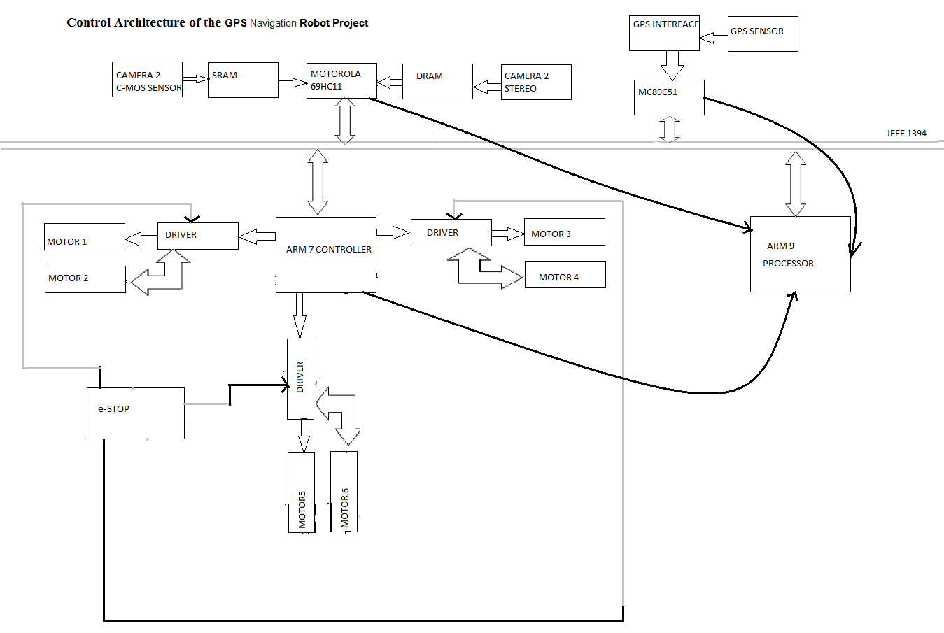
Our GPS Navigation Robot holds a micro processor and three micro controllers for multi task assignment.

The camera action, memory allocation, motor action and GPS way point verification are the synchronous process, where the continuous clock pulse is required.

Here by we use the Control Architecture,

ARM 9 with VME bus based micro processor.

ARM 7, ATMEL 89C51, Motorola 69HC11 are the three micro controllers used for speed and motion control drivers, GPS sensors and E-stop and Image Processing analysis respectively.

All the data has been send through IEEE 1394 fire wire bus controlled at fixed sequence.

Control Architecture of the GPS Navigation Robot Project

GPS Navigation Robot Final Year Mechanical Project

Positioning Sensors Used To Navigate On Rough Terrain:

Global Positioning Sensor:

Constructional Working of GPS:

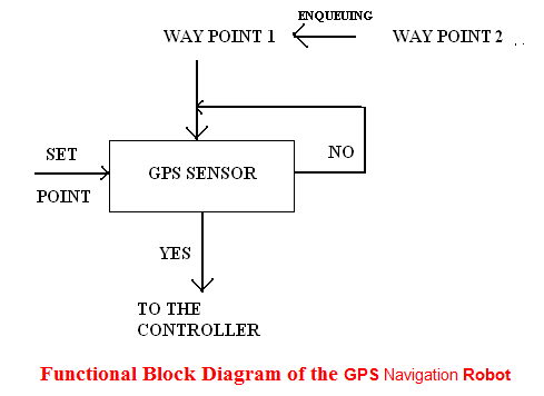
GPS sensor for Navigation Robot is used to navigate the bot reach the fixed destination. Here we use differential gps system, where the carrier frequency is very high even at low signal status certain adaptive methodologies to reach our destination. The functional block shows how the operation is performed by our bot. 

Functional Block Diagram of the GPS Navigation Robot:

 Functional Block Diagram of the GPS Navigation Robot

The block diagram of Final Year Mechanical Project clearly shows the functional working of gps that is here the set point (current position) is compared the first waypoint. Once the destination is reached the program memory enqueue the second way point and so on. If the designated waypoint is not reached again it checks till the destination is reached. 

Performing the Navigation Using GPS and Camera:

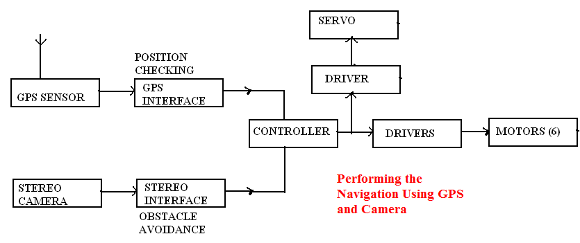
The effective way of using adaptive robotic technology is performing the complex operation simultaneously to do the desired operation. Similarly we have performed the simultaneous operation by performing both obstacle avoidance and positioning using stereo camera and gps sensor respectively. The main advantage of performing this GPS Navigation Robot operation is maximum nearness error can be avoided that is created during real time positioning. The block diagram clearly shows how the navigation is performed.

 Performing the Navigation Using GPS and Camera

e-Stopping:

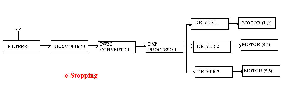
we perform the e-stop operation by providing stop signal to the driver .this we attain by converting the availabe frequency (crystal frequency) to PWM signal by using PWM converter .this signal is fed to the motor driver to stop the bot it is be. The block diagam shows the operaton of e-stopping.

e-Stopping

Robotics Final Year Project Ideas and Topics

Constructional Working of Robotics:

Electronic Engineering ECE Approach:

Camera:

In our Robotics Final Year Project we have two cameras

a) C-MOS camera sensor

b) Stereo camera

          The C-MOS sensor camera is placed at the center of the bot and the stereo camera is placed at the center of the bot and the stereo camera is placed at the top of the bot. the camera is tilt to an angle to make the projection perfectly projected to the center of the object.

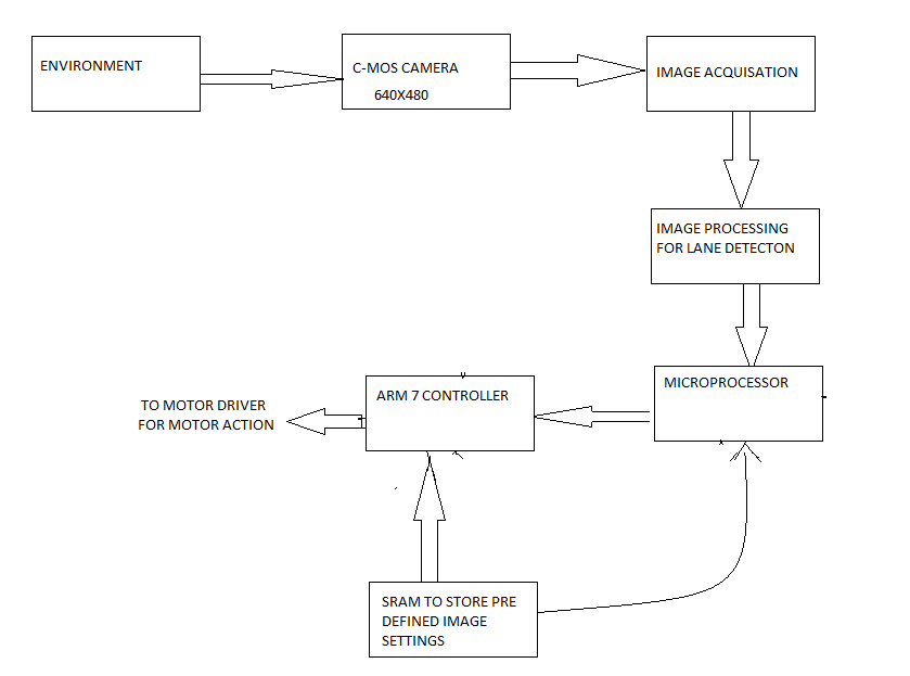
The C-MOS camera is used to perform more specifically for the lane detection. It is used because of its very high sensitivity to light, low power consumption and low cost. The output is digital, so it is directly fed to the controller to take the action. The functional block diagram shows the importance of camera action.

Technical Features of the Robotic Camera:

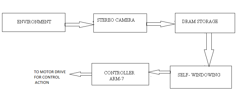
The Image processing and Image acquisition is performed by the on-board micro processor and the result of stereo and C-MOS camera is stored in SRAM (Static Random Access memory) and DRAM (Dynamic Random Access Memory) respectively.

The lane following is pre processing method, so the sample of images are pre loaded to the SRAM and it’s been cross checked by the controller and necessary action is given to the end effector. 

          The Dynamic image processing is carried out by using stereo camera where the self-windowing algorithm is used for real time variation. It is been stored in DRAM and synchronously signal is given to controller to perform the end- effector action.

Block diagram of the robotic project idea clearly show the importance of two cameras.

For lane detection:

For lane detection

Obstacle avoidance:

Obstacle avoidance

 Stereo camera is used for obstacle avoidance performances, since it has very high resolution.

Mechanical Engineering Projects on Robotics

The computational robotic feature was developed using a mechanical system engineering approach with emphasis placed on the understanding the inter-relationship between system components and on maximizing the overall system performance.

The Mechanical Engineering Project development of fully autonomous is a very complex task which holds the consideration of several factors. First, the appropriate view of providing and utilizing autonomy must be determined for each application. For example, the sensors used in this robotic project for image analysis and global positioning is high a time-variants, so this will directly create impact on any set of tasks designed.

Here we tried to manipulate the entire operation carried out by the Robotics Engineering itself that is it has its own capacity to take any decision under any environment without interference.

The integration is very difficult because it requires the assembly of many complex sub systems into a high degree of interconnection and synchronization.

From a Mechanical and Electronic engineering perspective, a well-defined architect provides the underlay framework for achieving reliable maintainable cost-effective system. N Such architecture does this by enabling methods coherently integrating diverse physical, functional and disciplinary sub-systems.

Functional block diagram of our robotic model:

General block representation: 

general

When we analysis these blocks we can acquire the solution for given problem

 environment

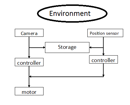
The general block diagram of Final year mechanical project clearly shows the importance of sequential operation to perform to attain the targets.

The camera which acts the eye for the bot which captures the environment and dynamically analyze the variation and is stored in temporary storage device and its being compared by the processor and action is given to the motor. 

Robotic Projects for Electronics ECE Engineering Students

Have keenly analyzed and designed autonomous robot by using various latest technique and mechanism to reach our destination.

Hereby we have spilt the Robotic Projects for Electronics ECE Engineering Students into mechanical and electronic parts.

The Electronic ECE consideration holds:

  1. The Camera specification ,
  2. Motor action,
  3. Microcontroller and processing unit,
  4. Global positioning system,
  5. Storage unit. 

The Mechanical consideration holds:

  1. The Design of the Robot,
  2. Kinematic design,
  3. Model using designing tool.

The Robotic Project describes the complete prototype of our design and the novel approach followed for construction.

COMPONENTS USED TO DESIGN OUR BOT:

HARDWARE SPECIFICATION: 

Microprocessor    : ARM 9 (VME bus based)

Microcontroller    : ARM 7, MC89C51, MOTOROLA 68HC11

Bus controller      : FireWire Controller (IEEE 1394 interface)

Motor                             : 40kg torque, 150 rpm, Voltage rating 24 V, Current 30 mA.

Camera                 : Stereo camera (obstacle detection)

                               C-MOS sensor (lane detection) 640×480,15FPS

SOFTWARE SPECIFICATION:

Visual C++     (Image Processing)

Embedded C   (Controller)

UNIX operator (Processor)