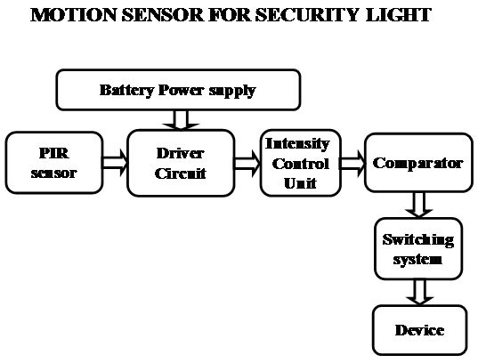
Motion Sensor for Security Light

The Motion Sensor for Security Light system uses Passive infrared sensor. These sensors are capable of sensing the presence of human being and post the same to the comparator IC. Now the micro comparator takes the responsibility of processing and judges the status of individual appliances and there by controls them using switches like relay, TRIAC.

The most important thing to be noticed here is the system is aimed for industrial, home, firm needs. So, there may be very high voltage devices like ACs and very low voltage devices like High intensity LEDS. Due to the presence of different appliances of different power ratings the design of the interfacing circuit should be done with utmost care.

Features:

1. Controlling the status of different electrical appliances
2. Live detection of human presence.
3. Low power consumption.
4. Reliable for industrial and domestic needs
5. High sensitivity.

The project focuses on the following areas:

1. Characteristics of PIR sensor.
2. High voltage device controlling.
3. Intensity controlling technique.
4. Embedded C program.
5. PCB design.

The major building blocks of this project are:

1. Regulated power supply with voltage regulator.
2. Micro controller.
3. Passive Infra Red Sensor (PIR).
4. Industrial appliances.
5. TRAIC boards.

Regulated power supply:

Block diagram:

Automatic Switching Of Induction Motor

Automatic Switching Of Induction Motor Abstract:

INTRODUCTION:  Now-a-days, water crisis in India has been reached to alarm proportions and its wastage during transmission is identified as the major cause responsible for the problem. So in order to resolve the issue to some extent we have come up with Automatic switching of induction motor in houses, this project which is a simple model used to conserve water as well as electricity, and can be implemented in the real time work.

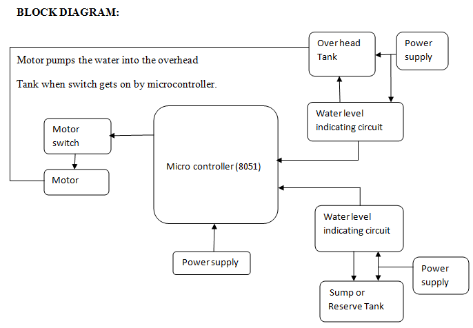
BLOCK DIAGRAM:

 Power supply

Over head Tank

Motor pumps the water into the overhead

Tank when switch gets on by microcontroller.

Water level indicating circuit

Sensor

Motor switch

Micro controller (8051)

Motor

Power supply

Water level indicating circuit

Sump or Reserve  Tank

Power supply

Automatic Switching Of Induction MotorEXISTENCE:

The basic idea for the project is water level indicating circuit. The water level indicator is operated with the help of IC 555 timer. The IC 555 timer is provided with inputs as soon as the level of the water in the sump or reserve tank reaches to a predetermined level. As soon as the water touches the predetermined level, the water level indicating circuit indicates its users by alerting through a beep sound.

PROPOSAL:

The above existed idea of water level indicator circuit is used twice to indicate the levels in the sump as well as the overhead tank and the output of the two water level indicators are given as the input signals to microcontroller. The Microcontroller is programmed in such a way that if water level is above the minimum water level in lower tank, water gets pumped to upper tank and as soon as the upper tank gets filled, motor switches off automatically.

TOOLS REQUIRED:

  1. Two water level indicators Software required:
  2. An overhead and underground tank Keil C Software.
  3. 8051 Microcontroller
  4. Power supply

  FEATURES AND ADVANTAGES:

  1. Constant and reliable water supply.
  2. Functions with minimal or no human interface.
    3. Easy maintenance; install and forget for years.
  3. Low cost and it is absolutely affordable by all.
  4. Prevents dry running of motor and so water, energy, power not get wasted.

APPLICATIONS:

  1. Monitoring and controlling of water level in reservoirs, dams are important in applications related to agriculture, flood prevention etc.
  2. Domestic, industrial, medical fields etc.

CONCLUSION:

The main objective of the project is to automate process of water pumping in a tank, ability to detect the level of water in a tank, switch on/off the pump. Hence from our proposal of “Automatic switching of induction motor,” water wastage gets controlled by constant and reliable water supply.

Stepper Motor Control Using AT89S52 MicroController

In this project “Stepper motor control using AT89S52 Microcontroller”, we implemented stepper motor controller circuit using PIC micro controller. The main objective of this project is to control the speed of the stepper motor in order to facilitate efficient working conditions in computer peripherals, business machines, process control, machine tools and robotics. Mainly in robotic process control and laser trimming applications.

Stepper motor control using AT89S52 for robotic applications and electronic gadgets had created room for the new technologies in terms of proving accurate services for the users.  Here I this project we used three switches to control the direction of the stepper motor i.e. clockwise, anticlockwise and stops respectively.

Power supply circuit:

The power supply circuit consists of an assembly of step down transformer, bridge rectifier, filter and regulator for converting 230v 5ohz ac supply into 5v regulated dc supply. The technical specifications about the power supply components and auxiliary circuit components are explained in this paper.

Youtube video link to view block diagram, circuit diagram

http://www.youtube.com/watch?v=yhe5MKbCREQ&feature=youtu.be

Software programming:

The program is written in Assembly language and compiled using ASM51 cross assembler. And the microcontroller is programmed using Atmel’s Flash programmer.

Instructions for PCB layout:

You can assemble the components on the printed circuit board for the stepper motor controller by the implementing the following process, firstly prepare the circuit layout – draw it on the copper circuit board – drill holes for the component terminals – remove the excess blur around the holes – assemble the components at respective places – solder and fix them at that positions – implement the electrical connections – test the designed circuit.

Download Stepper Motor Control Using AT89S52 MicroController Project Report

LCD:

A 16 Character x 2 Line LCD Module is interface to the micro controller to present the controlled output value using parallel port communication interface.

Electrical Load Monitoring System

Our project Electrical Load Monitoring System and breaker with digital display using microcontroller,(project Report)  provides better solution for the electrical distribution networks in reducing the over current losses in power transmission. This system works based on ATMEL 89C51 micro controller in the control system. The present system is provided with a digital display for the user.

Figure: hardware implementation of Load monitoring and breaker with digital display using microcontroller.

Project description:

The main objective of Load Monitoring System project is develop an micro controller based control system for effective control over the abnormal varying parameters of the electrical network under over load and short circuit conditions.

  • Mechanism: For monitoring the over load condition a current transformer is used such that the primary of the current transformer is connected to the load line i.e. the voltage at the primary winding of CT is directly proportional to the current flowing in the load line, the secondary of current transformer is connected to the filter and rectifier circuit for converting ac in to dc and then fed to A/D converter the output digital pulses are given to the micro controller so then the micro controller takes relevant action whenever the value crosses the preset value. The micro controller is conditionally programmed for this specific task.
  • ATMEL 89C51: The micro controller is constructed using ATMEL 89C51 Micro-controller chip, this special purpose computing system is ideal for low power applications. This micro controller had CPU, clock circuitry, ROM, Ram and I/O circuitry fabricated on single integrated chip. ATMEL 89C51 programming is done on embedded C assemble language programming.

Download Electrical Load Monitoring System Project Report

Youtube video link to view presentation

http://www.youtube.com/watch?v=H8sIty9N8hc&feature=youtu.be

Automatic Street Light Control Project

In Automatic Street light control project for on & off using light dependent resistor, we developed an automatic energy efficient device using micro controller based on light dependent resistor.

In recent day’s energy efficient control systems are gaining importance due to the implementation of embedded systems in the field of automation technologies, the key elements of the embedded systems are micro controllers.

Need of automatic sensing devices:

  • To conserve the wastage of electricity.
  • Limiting usage of power in unnecessary time.
  • To maintain accurate intervals of time in switching street lights.

Youtube video link to view block diagram, circuit diagram, components list.

http://www.youtube.com/watch?v=EDG1oZ_kdFg&feature=youtu.be

Operation:

The streets are automatically switched on when the light intensity falls below the threshold value, and the intensity of the light is sensed by the light sensors i.e. light dependent resistors, light dependent resistor exhibits high resistance under sufficient light and acts as an conductor i.e. low resistance path in times of low light intensity periods. This entire process is monitored by a micro controller based on the signals from the light dependent resistor.

Hardware components:

  • Micro controller – low power high performance 18F452 Microcontroller is used in the project which manipulates the circuit based on the light dependent resistor.
  • Power supply circuit – a combination of step down transformer, bridge rectifier, filter, regulator used for getting 5v regulated dc output.
  • Display unit – 16×2 LCD modules is used in this project as an output device.
  • Triggering circuit – relays are used at the output terminals of the micro controller in order perform the on/off operations for the circuit.

Download Automatic Street Light Control Project Report

Redtacton Technology Projects

In Redtacton Technology Project report we explain about red tacton which is a new revolutionary concept in transmitting data over a limited distance by means of the electrical field produced by the human body. In recent days this red tacton technology had made tremendous changes in the field of security and several automation activities.

The electric pulse on the surface of the human body acts as a medium for the transmission of data in between the transmitter and the receiver in the red tacton chip. These red tacton chips are capable of accepting any type of data signal and transmit these signals through the human electrical field.

Briefly “It is a new human area networking technology which makes use of the human body circumference as a mere path to transmit the data”.

Working principle:

The red tacton chip at the transmitter section emits the data and transmits this signal in the human body charge field and then the chip at the receiver section takes the pulse signal and decodes to required format.

Developed prototype:

In this particular project we developed a sample red tacton prototype. The red tacton device consists of two main devices at the sending end and the receiving end.

  • Portable Card-Size Transmitter- it can transmits data at a rate of 230kbps in unidirectional transmission mode.
  • Embedded Receiver – its transmission rate is as same the Portable Card-Size Transmitter with same transmission mode.

Download Redtacton Technology Projects Report

Students can download seminar report and related projects with project PPT from below link.

Mobile Ad-Hoc Network Project

This Project Report on “mobile ad-hoc network” is give an outline description of mobile ad-hoc network nodes and its application with complete explanation of its architecture.

Mobile Ad-Hoc Network Project Report

Evolution of MANET:

MANET is a group of mobile nodes into an ad-hoc network which terminates the need of centralized structures. Till now these mobile networks are dived into three categories.

First generation MANETS – in early stages these networks are called as Packet Radio Networks i.e. PRNET, is implemented in medium distance access and different networking capabilities in a combat environment.

Second generation MANETS– here the primary PRNET’s are further enhanced to improve its radio frequency performance by designing them into smaller and less complex and cost effective devices. While these advanced mobile networks are termed as GloMo (Global Mobile Information Systems) and the NTDR (Near-term Digital Radio) are the bi products of this research.

Third generation MANETS – present day mobile networks are termed as third generation, these are mainly categorized based upon three protocols namely proactive routing protocols, reactive routing protocols and hybrid routing protocols. Each protocol had its own benefits and these are clearly explained in the coming sections.

Youtube video link to view Presentaion

http://www.youtube.com/watch?v=8pV0uUkU_Bk&feature=youtu.be

Secure data transmission in MANET:

Data transmission in MANET is greatly depending upon two factors. One is import authorization and export authorization. The import authorization takes decisions about the modifications of the routing information while the export authorization takes decisions based on the request routing information.

Download Mobile Ad-Hoc Network Project Report

Modern Security Systems with Message Transmitter Project Report

In this modern electronic era there is a rapid advancement in Modern Security Systems. In this project we presented a new concept “A security systems with message transmitter”. This is an ideal modern day security system with intent to provide security for theft prone areas like banks, museums, commercial complexes etc; we meet the basic security requirements by using this system and mainly this system works based on the signal interference phenomenon i.e.

when the continuous beam is interrupted it generate the error signal for the user. Here in this project we use infrared rays to detect the interruptions, the infrared sensors senses the presence of the humans and activates the security system and sends information to the security authorities. We use two infrared sensors one for signal generating and the other for signal transmitting and receiving. And the distance between the two sensors can be varied to required length.

Modern Security Systems Operation Explanation:

Here the device operation is controlled and coordinated by a micro controller the signal receiver section is interfaced with the micro controlled, if any interrupt is generated the micro controller gets high output and this micro controller activates the relays and these relays energies the alarm circuitry.

Download Modern Security Systems with Message Transmitter Project Report

This system implements cassette player mechanism and the recorded information is transmitted as a modulated wave by frequency modulated transformer, and condenser MIC used in this project is an highly sensitive device it can sense very low signals accurately. And in the output section we provided a seven segment digital display, the receiving module is fixed at the security station with an audio amplifier.

Modern Security System Advantages:

A sample module is presented and an experimental survey is conducted, we implanted this device practically. Coming to its advantages this system is far better than the conventional security devices it highly reliable, efficient, low power consumption device. By interfacing GSM modem in future we can receive security SMS alerts to our phones.

Wireless Monitoring Systems Project Report

The main objective of Wireless Monitoring Systems Project is to perform continuous monitoring the patient conditions, and providing accurate information in emergency situations, the increase in accessibility in wireless technologies paved path for the inventions of new remote monitoring systems.

Wireless Monitoring Systems Project Report

Wireless Monitoring Systems Implementation:

Implementing wireless sensing devices with high flexibility and portability, here in our project we implemented a real time wireless communication network for short and medium range of distances, this system is capable of determining the heart beat of the patients and the temperature calculations based the micro controller signals, we use an GSM module to transmit the data from one place to other and the micro controller controls the transmission process.

Youtube video link to view block diagram, circuit diagram

http://www.youtube.com/watch?v=kik2TvRpyBg&feature=youtu.be

Here we send information in the form of SMS from the transmitter to the medical expert, and also this system displays the information on the computer screen, these sensors senses the abnormal conditions and an alarm is blown in emergency situations.

System Requirements:

The hardware of this device includes an low power AT89C52 Micro Controller which is interfaced with the GSM modem, LM35 Temperature Sensor, analog-to-digital converter (ADC) for interfacing microprocessor to convert analog data into digital format, LCD display will acts as an output device, and the maximum voltage that the circuit will operates at 5vdc, for that we need to step-down the 230v ac to 12v ac and then rectified into 5v dc using a Bridge rectifier, and then this rectified voltage is regulated using an voltage regulator and feed to the circuit, At the load we connect a capacitor to minimize the ripple content.

The hardware design and block diagram representation is clearly explained below, so far we had implemented this new device successfully and practical tests are conducted.

Download Wireless Monitoring Systems Project Report

These health care sensors are playing vital role hospitality; it is a multipurpose system and can forecast the different conditions at a time, easy to operate and comparatively low price devices, and highly reliable with less complexity.

Vehicle To Vehicle Communication System Project Report

Abstract for Vehicle To Vehicle Communication

Objective of Vehicle To Vehicle Communication System project is to avoid the roadway collisions and to drivers prior to the collision. Accidents are taking thousands of lives every day so with intent to reduce the adverse effects we implemented this project based on vehicle to vehicle communications systems, with the rapid advancement of wireless communication systems had paved path for the vehicle to vehicle wireless communication based warning systems.

Vehicle To Vehicle Communication System

Introduction to Vehicle To Vehicle Communication

In this project the wireless data communication is provided by using ZIGBEE concept, this ZIGBEE technology is a high level wireless communication protocol using small and low power based wireless networks. And are the standard based communication networks had unique advantages like low cost, low power consumption wireless sensors since these are intensively applicable in modern electronic components these are the ideal choice for secure networking.

So far based on the steady analysis of present day situations we implemented an effective system based on control policies, service differentiation methodologies, and complex emergency warning dissemination.

The ultrasonic sensors are used as a distance measurement device for this system, a low power, high-performance CMOS 8-bit AT89C51 microcontroller is used to control the overall operations systematically. Piezoelectric sound buzzer is used to warn the user.

DownloadVehicle To Vehicle Communication System Project Report

Project Advantages:

This wireless communication system project is useful to reduce accidents.

It helps better communication system between two vehicles by calculating distance and speed of other vehicles. Cost required for installation is low and easy to design with low investment.