E-kart Website WordPress Theme Project

Abstract

In today’s day to day life purchasing of products by visiting stores has become a tough job. As a standing in a queue for making the payment of the product has become difficult for customers. To overcome these difficulties, we are coming up with E-kart.

E-Kart is an e-commerce website which helps to choose a wide range of products through your desktop or smartphone rather than visiting the outlets. It is developed using word press which is an open source blogging platform and content management, the basic e-commerce functionality in word press can be achieved through Magento. It is been developed to handle accurate stock and also to overcome a payment gateway problem. E-Kart ensures that it accepts a review from our genuine buyers.

Word press power stats save the tracking information and analytics data in the backend. E-Kart uses “Machine Learning” analysis to know the exact number of customers visiting our site track user engagement, it also shows us the product with high demand in that particular to understand the seasonal market demands for seasonal product supply.

The Modules used in the project are

1. Admin
2. Customer

Admin:

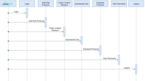
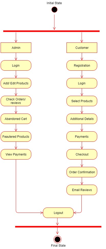
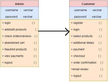
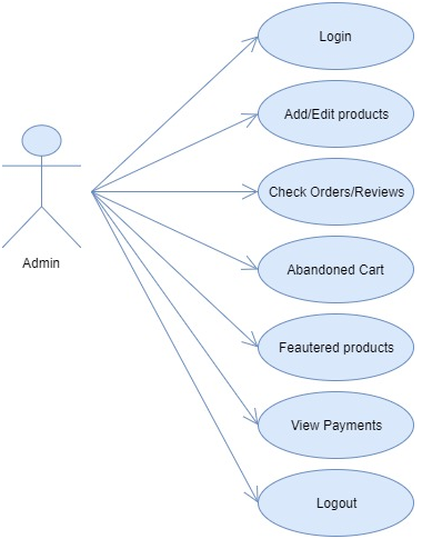
Admin will login into the application with the default username and password. Admin can add and edit the products and product details. He can also view the orders placed by customers and reviews by customers. Admin can also view the abandoned cart products and featured products. Admin can also view the payments.

Customer:

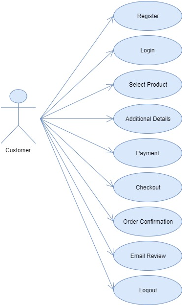
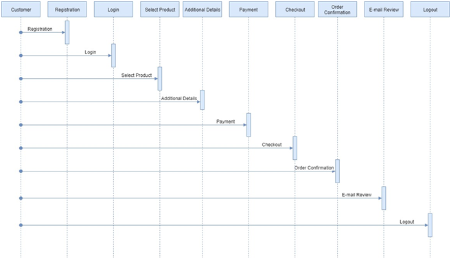
The customer can view the application by registering or without registering as a guest user. But the guest user has limited functionalities compared to the registered user. Registered customer must log in with the username and password after logging in he can select the products and add them to the cart. After the product is selected customer needs to provide some additional details like shipping address after that the payment will be initiated by the customer, after successful payment the customers will get 3 emails listed as Order copy, Delivery Details Copy and Thanks Copy.

In this application, we used 2 Plugins namely in this application they are

1. Akismet
2. Recomendo

Existing System:

In the Existing system, we are experiencing high crowd in the stores which make for us select the products and making the payments also takes a lot of time in some reputed stores.

Proposed System:

In Proposed System the admin will maintain a wide range of products at affordable prices for customers and it makes easier for those who buy in the application. If a customer leaves the product in the cart without buying and exits the application then the customer will get the mail after particular threshold time.

UML Diagrams:

Use case Diagram for Admin:

Use case Diagram for Customer:

Sequence Diagram for Admin:

Sequence Diagram for Customer:

Activity Diagram:

Class Diagram:

Mini project on Program Outcome Assessment

Abstract

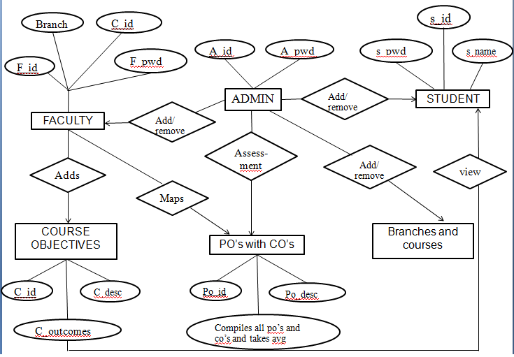
Program outcome assessment application is an online assessment application which enables the faculty to add Course outcomes of their respective subjects and map it with program outcomes of their course.

This application also helps the students to view the course outcomes of their respective subjects.

Assessment is used to identify that how each course is contributing to program outcome.

Existing System

  • Course Outcomes and Program Outcomes mapping are done manually.
  • The head of departments will have to wait for the faculties to submit the outcomes.
  • It is a time-consuming process.

Proposed System

  • The faculties will add the course outcomes of their respective subject and the administrator can view by logging in.
  • Mapping is done by keeping the correlation level in the range of 1-3
  • It segregates the subjects and it is user-friendly.

Modules

Administrator

  • adds branches and courses
  • update courses
  • performs an assessment of course outcomes with program outcomes

Faculty

  • adds their respective course outcomes and perform mapping of course outcomes with program outcomes

Student

  • can only view the courses

Admin Functionality:

  1. Start
  2. Login into the account, if not registered register with required details.
  3. If the user is administrator they can login, add branches, new faculty and courses.
  4. Performs assessment of course outcomes with program outcomes.
  5. Stop

Faculty Functionality:

  1. Start
  2. Login into the account, if not registered register with required details.
  3. If the user is faculty, they add course outcomes of their respective subjects and performs mapping of course outcomes with program outcomes.
  4. Stop

Student Functionality:

  1. Start
  2. Login into the account, if not registered register with required details.
  3. If the user is a student, they can only view the course outcomes.
  4. Stop

UML Diagrams:

ER Diagram:

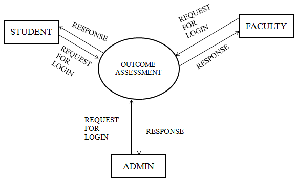
Level-0 Data Flow Diagram

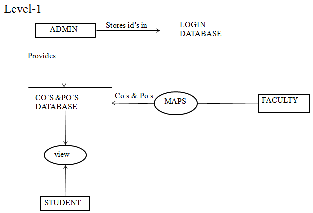
Level 1 Data Flow Diagram:

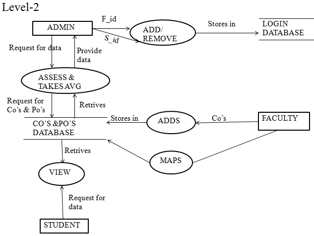
Level 2 Data Flow Diagram:

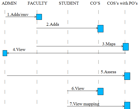
Sequential diagram:

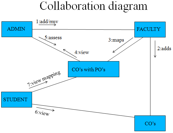
Collaboration diagram:

Database Tables:

Admin Table:

  • admin_id number(10),
  • name varchar2(20),
  • password varchar2(20),
  • email_id varchar2(30),
  • address varchar2(200),
  • constraint pk_admin primary key(admin_id)

Faculty Table:

  • faculty_id number(10),
  • course_id number(05),
  • password varchar2(20),
  • branch varchar(10),
  • constraint pk_faculty primary key(faculty_id)

Student Table:

  • student_id number(10),
  • password varchar(20),
  • student_name varchar(20),
  • constraint pk_student primary key(student_id)

Course Objectives Table:

  • course_id number(10),
  • course_desc varchar(20),
  • course_outcome varchar(20),
  • constraint pk_courseobj primary key(course_id)

Program Outcomes Table:

  • po_id number(10),
  • po_desc varchar(20),
  • po_average varchar(20),
  • constraint pk_programoutcomes primary key(course_id)

Easy Search Guide Java Project

Abstract:

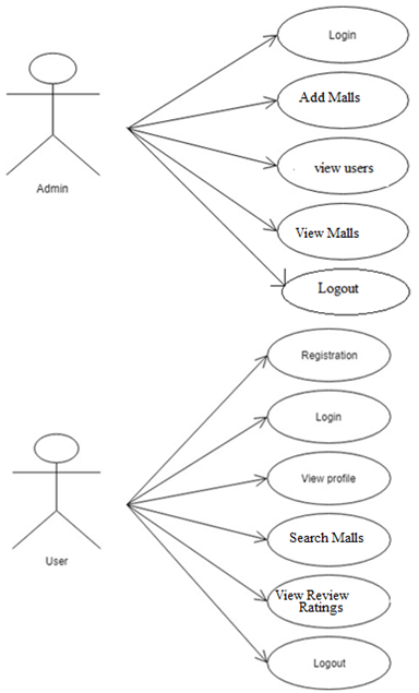
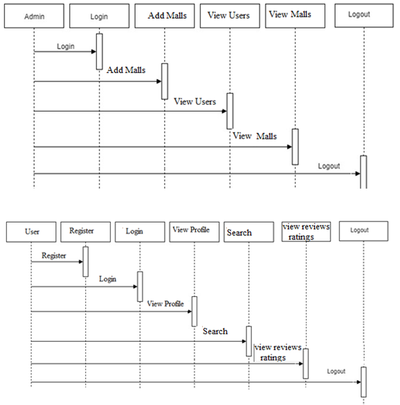
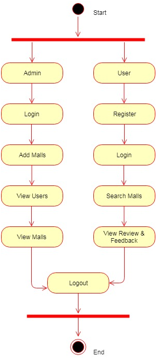
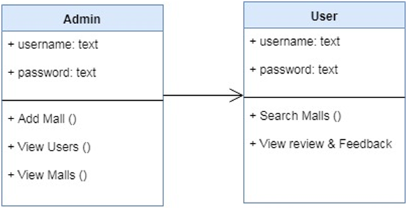
Are you new to the city? Confused where to go on a weekend or could not find any relevant information on the internet about a destination to spend your quality time. Don’t worry that’s what we are going to provide you. A single place where one can find all the malls in your city, with detailed information about the things one can do like shopping, watching movies, dining, and gaming for kids.

This Easy Search Guide application not only provides details of malls but also provides offers one can avail in the shopping stores or in restaurants and also current movies running, with everything reviewed and rated by the users. We make everything easy for the users with our information so that users can easily find their next shopping destination or a place where the family can spend their day out without any hassle.

Existing System:

Though we have applications to find the restaurants nearby or you can find the malls nearby on maps. We don’t have any single application that provides information on all malls and restaurants along with offers and reviews altogether. We don’t know about the deals or offers provided by a store at the mall until we visit in by a person. We even cannot find such information on the web.

Proposed System:

We are going to build a responsive single page web application using HTML5, CSS3, and React.Js for the front end part and Node.js with a relational database to process the data from the database and provide it to the front end. We choose React and Node. js because of their maintainability, prototype, fast nature, and reusability.

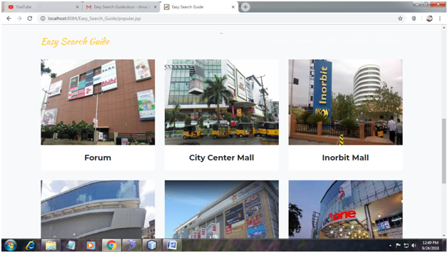
The Easy Search Guide application will list down the malls nearby using geolocation API or the user can manually select from the list of cities provided. When clicked on the mall list of categories will be available like shopping, dining, entertainment depending on the selection, the user will be shown the list of shopping stores or restaurants or movies available and the current offers which user can avail. Users can see the rating or reviews of the shopping store or restaurant and if they want to add a review or rate a store or restaurant they need to log in with their Google or Facebook account.

Use Case Diagram:

Sequence Diagram:

Activity Diagram:

Class Diagram:

Banking System through Voice Java Project Report

ABSTRACT

Overview:

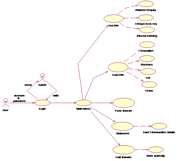
This application is about the banking system through voice. The main aim of this application is to provide an easy way to fund transactions from one account to another account with the help of telephonic conversation.

Current Scenario: 

  • The present scenario has only two ways for transfer the funds from one account to another account. They are either doing the manual transactions on bank or using internet services.
  • This will become as a drawback for the people those who don’t have the internet service and those people who don’t know how to use internet.
  • We may not have a chance to every time come to bank.

Proposed Scenario: 

  • To overcome this type of problem, we are finding a new way which is used very easy by every common man is “VOICE BANKING”.
  • This will become very use for the people those who don’t have the internet service and those people who don’t know how to use internet. 

Application Features: 

  • Should provide the security for account holder name and credit card number.
  • Provides easy way of transfer the funds from anywhere.
  • Getting account holder information. 

Purpose of the project:

The purpose of this project is to use the services of bank like money transfer, knowing about the loan information, our account balance; our statement and we can also make and activate our cheque book request and internet banking services through voice only and without using any internet service. 

INTRODUCTION

There are a number of applications for speech coding. One of its applications is in “VOICE BANKING”. Speech coding plays an important role in voice banking where the compressed words from a telephone line are to be recognized by the speech recognizer used at the banking end. The speech recognizer at the banking end tries to understand the compressed spoken words in some way or the other and acts thereafter. With voice banking, the user can access the following services.

  • The user can check for balance on all his savings, current and loan accounts.
  • The user can know the history of his account like the debits, recent deposits, interests and check payments.
  • The user can make loan payments and Funds Transfer between two accounts.
  • The user can check for interest rates on various types of loans and on deposits.
  •  The user can stop the payments to be made.
  •  The user can make a report about the stolen or lost card.
  •  The user can have information about the ATM locations, bank branches and working hours.
  •  The user can speak at any time of the day to the bank’s customer service centre.

SOFTWARE REQUIREMENTS:

  1. Prophecy -8.0.98.2
  2. Jdk 1.5 (or) 1.6.
  3. Oracle 10g database.
  4. Tomcat web server.

INPUT AND OUTPUT

Inputs:

  • Users enter his or her account number and password.
  • User should select one from main menu
  • For fund transfer user should enter receiver account number and amount.
  • For any request user should prompt yes or no. 

Outputs:

  • Account information.
    • Balance enquiry
    • Successful creation of cheque book request
    • Successful activation of internet banking.
  • Loan information details.
  • Get the details of education,home,business and car loans
  • Fund transfer.
  • The amount of rupees 5000 is successfully transferred from sender account number. (When it is valid receiver account number).
  • Sorry the mentioned account does not exist. (When it is invalid receiver account number).
  • Call transfer.
  • User may contact with manager/assistant manager. 

Entity Relationship diagrams:

System Work-Flow:

Use Case Diagram for Main Menu:

Use case for fund transfer:

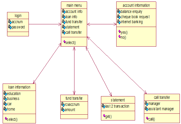
Class Diagram:

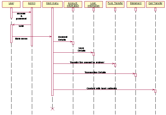
The sequence for the main menu:

Sequence for Account Information:

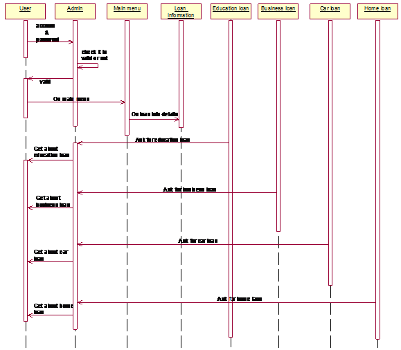
Sequence for Loan Information:

Sequence for Fund Transfer:

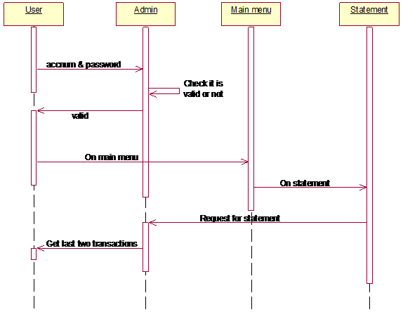
Sequence for Statement:

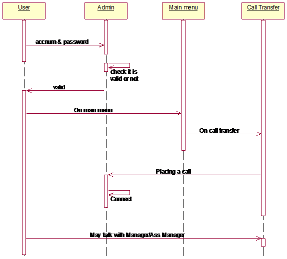
Sequence for Call Transfer:

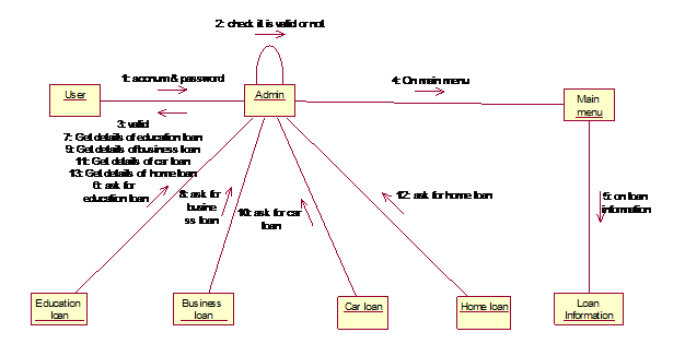
Collaboration for Loan Information:

Collaboration for Fund Transfer:

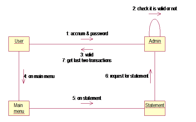
Collaboration for Statement:

Collaboration for Call Transfer:

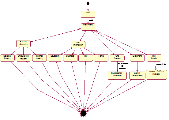
State chart diagram:

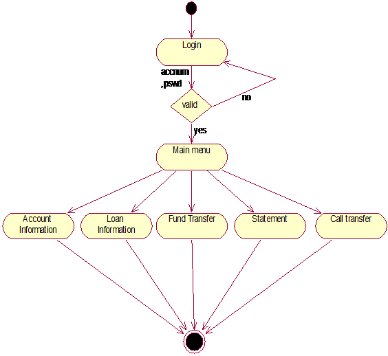
Activity diagram for Main menu:

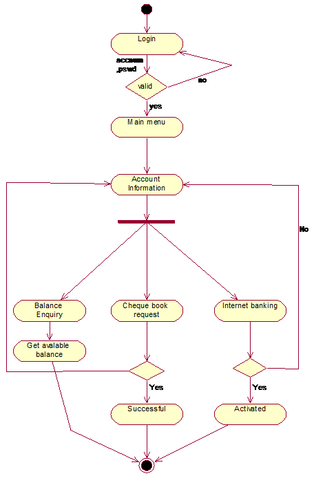
Activity diagram for Account Information:

Conclusion

Voice banking is a very useful banking service in our daily life. Using it the users can access to their account information and other banking services like to know about the loan information and user also transfers their money to other users in 365 days a year, 7 days a week and 24 hours a day just by making a simple phone call.

Bakery Store Final Project Synopsis

The below Requirements for a model for Final Bakery Store Project:

  1. Minimum 6 entities
  2. Minimum one inheritance – with 2 subclasses
  3. Minimum one interface with one implementation
  4. Role based model – Eg., Admin and Regular users should have different functionalities
  5. Should implement CRUD functionality for all entities – based on user roles – it should be logical with your model
  6. Should use Java collections for entities relationships. Design your model in such a way that collections are used for associations between entities.
  7. This task is mainly to think logically about the functionalities that a system can perform based on user roles in order to create the design.
  8. DDL statements with Entity relationship diagrams of all the entities.

Classes List:

  • Bakery Items
  • Users
  • Admin
  • Customers
  • Order
  • Account

Interface

  • Payment

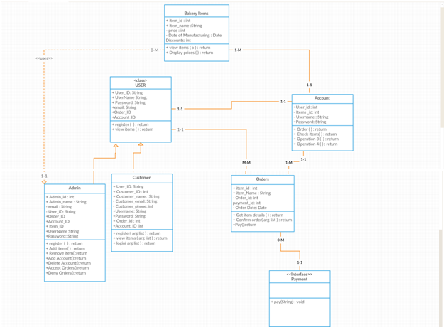
Class Relationship:

  • Bakery_Items to Account (MANY TO ONE)
  • USER to ACCOUNT(ONE TO ONE)
  • Customer and Admin are subclasses of User(inheritance)
  • User to Orders(ONE to MANY)
  • Account to Orders(ONE to MANY)
  • Payment<interface> to Orders(One to Many)

UML Diagram for Bakery Store

Database Table List

  • Bakery_items
  • Users
  • Account
  • Orders

DDL Statements:

Table Bakeryitems

Create Table BakeryItems

  • Item_id number(10) NOT NULL,
  • item_name varchar(50) NOT NULL,
  • price number(10),
  • DateOfManufacturing DATE,
  • CONSTRAINT BakeryItems_pk PRIMARY KEY (item_id),

Create Table Account

  • Account_id number(10) NOT NULL,
  • Customer_username varchar(50) NOT NULL,
  • customer_id number(10),
  • CONSTRAINT Account_pk PRIMARY KEY (Account_id),
  • CONSTRAINT fk_User
  • FOREIGN KEY (User_id)

Create Table User

  • User_id number(10) NOT NULL,
  • username  varchar(50) NOT NULL,
  • password  varchar2(10),
  • email  varchar2(10),
  • phone  Number(10),
  • Account_id varchar2(10),
  • CONSTRAINT Customer_pk PRIMARY KEY (customer_id),
  • CONSTRAINT fk_Account
  • FOREIGN KEY (Account_id) 

Create Table Order

  • Order_id number(10) NOT NULL,
  • item_name  varchar(50) ,
  • item_id  Number(10),
  • order_date varchar2(10),
  • payment_id  Number(10)
  • CONSTRAINT Order_pk PRIMARY KEY (Order_id),
  • CONSTRAINT fk_Bakery_Item
  • FOREIGN KEY (Item_id)

Displaying Smart Phone Data Android Project Report

Problem Statement:

Nowadays MNC companies are not allowing using smartphones in the workplace because the data is being transferred illegally. Due to this, the user is unable to know any important or urgent information.

Existing System:

In the existing system, some information such as missed calls and battery, messages information, referred to as device-oriented information. However, such information is related to a user. For example, if the user works in a company and cannot carry his mobile due to security issues then the user is unable to view the information.

Proposed System:

The application is based on sharing information such as battery status; miscall info and message from the Android device to web application, i.e., whenever the battery drains or any miscalls or when a message comes all this information will be updated on the server system and the user can view that information using the web application from anywhere.

Product Scope:

Users can access their device information from anywhere, anytime using server services.

Literature Survey:

The application is based on sharing information such as battery status; miscall info and message from Android device to web application, i.e., whenever the battery drains or any miscalls or when a message comes all this information will be updated on the server system and the user can view that information using the web application from anywhere.

Software Requirements Specifications

Introduction

The software product described in this document is Displaying Smart Phone Data. The main purpose of developing this system is to share device-oriented information i.e., location details to the server and retrieve that information from a server using Web Application

Product Scope

Users can access their device information from anywhere, anytime using server services.

Product Functions

The major functionalities of this website will be as follows:

  • User credentials.
  • Sending data from Android Device.
  • Displaying data.

Development Environment

Software and hardware required to develop this project are mentioned as follows.

Software requirements

Programming Platform: JDK 1.7, Android SDK

IDE: STS (Spring Tool Suite)

Web server: Google Server (Google App Search Engine)

Database: Google Database

SYSTEM FEATURES

The major functionalities of this project will be as follows:

  • User credentials.
  • Sending data from Android device.
  • Displaying data.

User credentials

The user provides registration details and registers, then logins by providing username and password.

Functional Requirements

Authentication:

It provides authentication to individuals who wish to get connected. The registration details are stored in the database and whenever the user logs in, the user credentials are retrieved to check whether the user is an authorized user or not.

If the details entered do not match with any of the existing data then the system displays a warning.

Sending data from android device

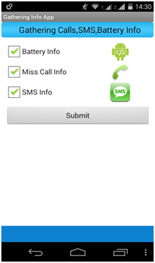
Users click in android mobile to get missed call, messages and battery information.

Functional Requirements

A user can choose information to push to external services. The application currently supports three types of information:

the battery information of the device, SMS and missed call history. It shows how to get mobile device related information and send it to the server.

Displaying Data

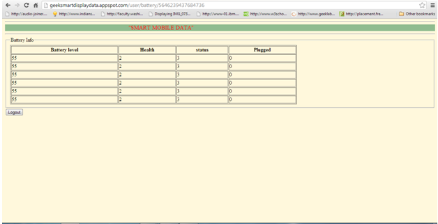
In this, the system creates a web Application to show the missed call, messages and battery information.

Functional Requirements

In this module system will develop a web application which can access, show the data pushed from the device to the server. It will show the missed call, messages and battery information using the data grid

DESIGN DIAGRAMS

UML DIAGRAMS

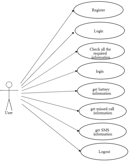
Use-Case Diagram

Figure: Use-Case diagram for the User

The user interfaces with the server. When the user login for the first time a user has to register the details. After registration, the user logins and receives the information about the battery missed call and SMS history of the phone. Finally, the users can log out.

Class Diagram

Figure: Class Diagram for the user, Web application and Database

The above figure depicts the three main classes User, Application and Database, where the user depends on the Application. The user interacts with the Application using Username and Password. And the Application is associated to the Database to retrieve and for storing information about the phone.

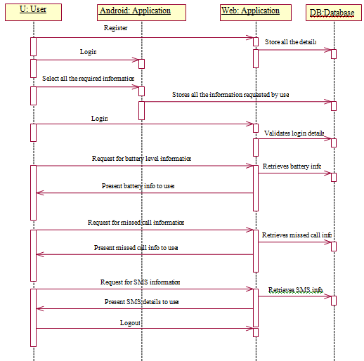
Sequence Diagram

Figure: Sequence Diagram for the User

The sequence diagram shows the external flow of the system. The user logins with the server by giving username and password. Then the user receives the information about the battery, missed call and SMS history by requesting the server. After the user receives the information the user can log out.

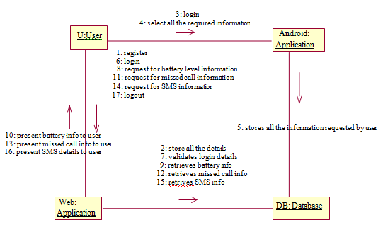
Collaboration Diagram

Figure: Collaboration Diagram

Test Cases:

Test Case #: 1 

Test Case ID Test Case Type Test Case Description Expected Value Actual Value Result
1 Entering URL of the Web application Checking status of Google Server and URL, through which the application begins The application should begin If the URL entered is corect then the application starts functioning Application starts successfully
1 Entering wrong URL of the Web application Checking status of Google Server and then entered URL is wrong The application fails to begin Entered URL is incorrect the application doesn’t begin Unable to start the Web Application

 Test Case #: 2 

Test Case ID Test Case Type Test Case Description Expected Value Actual Value Result
2 User Registration Registration details of the user will be present here If the user name has unique identity then user get register successfully User is getting Authenticated User is successfully registered.
2 User  Registration gets failure Without entering anyone of the fields if the user clicks on submit then alert message will be displayed. User will not able to registered An alert will be displayed An alert will be displayed like “Enter all the fields”.
2 User  Registration gets failure When a user tries to register with the same user name, then user will not get registered. User will not able to registered A alert is displayed An alert will be displayed like “Username already exists, try another”.

 Test Case #: 3 

Test Case ID Test Case Type Test Case Description Expected Value Actual Value Result
2 User Authentication User credentials of user are authenticated. User credentials are to be correct


User gets Authenticated The user login is successful and is authorized to use the system
2 User  Authentication gets failure User credentials of user are not authenticated. Login details are to be incorrect User Authentication

Fails

The user login is failed and is not able to use the system
2 Login into website Without giving User credentials Trying to login without providing User credentials. An alert is to be displayed An alert is displayed The user login is failed.

  Test Case #: 4

Test Case ID Test Case Type Test Case Description Expected Value Actual Value Result
4 Navigates to Home page The user tries to view the information. The required information(call,

Sms, battery) information should be displayed.

Information is retrieved from database The information is displayed successfully.
4 Home page cannot be redirected The user tries to view the information but home page can’t be displayed. The error page will be displayed. Due to some connection problem (Sms, call and battery) information of mobile will not be sent to the database.


This webpage is not available.

 Test Case #: 5 

Test Case ID Test Case Type Test Case Description Expected Value Actual Value Result
5 Mobile Status Changed Mobile Status is changed automatically web service will be called. The information can be viewed by the user. (Call, sms and battery) information will send it to the database.


The information can be retrieved.
5 Mobile Status not Changed Mobile Status cannot be changed. The information can’t be viewed by the user. (Call, Sms and battery) information will not be sent to the database.


The information can’t be retrieved.

 Screen Shots

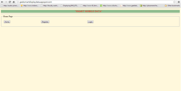
  • Home Page

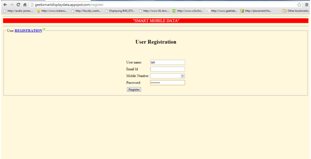
  • Registration Page for USER

  • Entering details in Registration Page

  • Displaying Alert box to enter all details.
  • Entering all details
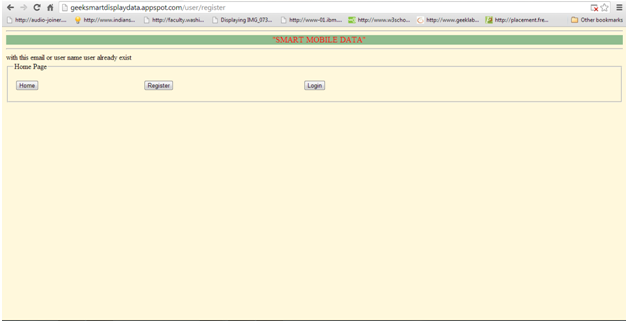
  • Redundancy of USER name

  • Successful Registration of User
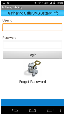
  • Login page in Android Phone

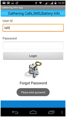
  • Displaying Alert message

  • Displaying an alert message
  • Selecting all mobile information

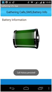
  • Sending information to the database
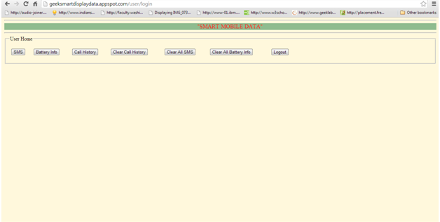
  • User Login Page
  • Displaying an error message
  • Successful Login

  • Displaying Battery Status

  • Displaying a message if there are no results to show
  • Displaying information on Call History.
  • Displaying information of SMS history
  • Clearing the information

Conclusion and Future Scope

This application, “Displaying Smart Phone Data” is based on sharing information such as battery status; miscall info and message from android device to web application, i.e., whenever the battery drains or any miscalls or when a message comes all this information will be updated on the server system and the user can view that information using the web application from anywhere.

In future, this project is useful to any Android mobile user where the user can get his mobile information data using Android Broadcasters. Before using the application, the user should register. This application detects the mobile information like SMS, call and battery information. So that the user can view the mobile data in Flex Application.

Online Voting System ASP.Net Project Synopsis

SYNOPSIS

Project Title: Online Voting System

ABSTRACT:

This is a web page in which we create a voting system. We consider that all voters are preregistered by admin when the voter login for voting he/she can give only one vote. This project developed for threat free and user-oriented Online Voting System. Online Voting System is made for the voters who want to vote for their favourite candidate sitting at home or from any location.

INTRODUCTION:

The online voting system is implementing in Asp.net using MsAccess database.  The main aim of the online voting system is to develop communication with candidates. This web page used by the college for mini-election in which voters who have registered by admin can vote for their favourite candidate. The voter will log in and give its vote to its candidate to whom voter wants to vote.

PROJECT OVERVIEW:

Admin will register voters and candidates who are standing in an election or any other activity. Only admin can check the result.

PURPOSE:

To make the communication strong with the candidate and to provide the easy way for voting. To increment the voting percentage. As many people have their physical issue that they cannot go to voting boot so this system gives facility to voters that they can vote from any place or any location.

PROJECT SCOPE:

As this project is online so it is easy for voters to give the vote to their favourite candidate from any place or location

PROBLEM DEFINITION:

The voters must keep their login id and password secrete because the voter can vote from any place. As the project is online so anyone can vote using its login-id and password.

Project Objective:

The casting of the online voting system from virtually from college building and display voting results for the administrator to analyze and provide a most secure and user-friendly online voting system.

CONCLUSION:

By using the online voting system it will become possible to cast vote easily and without partiality. Thus seamless voting using the central database is possible and will cause no repetitions of votes.

Website Content Management System Development using WordPress

As a part of this website development work, the student needs to create a website in WordPress Blog. Here we will be responsible to select a theme for our website, for example, their portfolio or a hobby.

The WordPress website must look professional and contain the following features.

  1. Create a WordPress website by selecting an appropriate theme/template.
  2. Create a minimum of five pages on this WordPress website, make sure these all the pages are available in the main menu
  3. Create a secondary menu to display the facebook, twitter, google plus, social links on the website.
  4. Use WYSIWYG Text Editor and create a post with at least the following features
    1. Hyperlink
    2. Photos
    3. Text alignment
    4. Add a table on the page
    5. Display share to social media options
    6. Make use of HTML editor
  5. Create a photo gallery and display the link in the menu
  6. Post a video on the page
  7. Create a poll and display it on a page
  8. Display your blog on the menu
    1. Add a blog category either to top menu or any other side menu.
  9. Create at least five blog articles and categorize them in at least two categories
  10. Add widgets on your pages or blog entries

Structure:

This web application will be the mini project of the students’ final year. Students must keep their website until the end of the second semester to keep their project marks since there is no hard copy for the submission. As a part of the web project submission, students must provide a cover page which will have the following information and your website address. Students will upload this document to Moodle to submit the project. The application must be uploaded on Moodle prior to its due date, whereas the project will be assessed in class.

Include the following in your cover page

  1. Full name
  2. WordPress website address

Include the following in your website mandate:

  1. A brief summary of the WordPress website
  2. Theme or Template used in the web project
  3. All menu options in bullet form
  4. Screenshot of each page with a brief description on each menu item

Project Report on Customer Management System

This Customer Management System project has the below forms:

1)  Form: CUSTOMER DETAILS

a) When Consumer Applies for New Connection, the administrator will get all the Details from the customer and save it to the DataBase Table “CustomerTemporaryDetails” except Phone numbers and Load details all the information is mandatory. Load details, at least a row should be filled. (Eg: lights).

b) In this Form, a unique application number, CustomerID, and RecieptNo will generate. Depending On the Supply Category, Registration amount will vary.

c) Application Number will generate according to Office Ids. When User loads this form User ID will automatically be displayed from Registry which is stored when The user enters his login details.

d) All the Primary Data will be Stored in the CustomerTemporaryDetails and Load details will be Stored in the CustomerPreliminaryLoadDetails.

e) Application  Status is updated as “ 1” in customerTemporarydetails indicating a New Connection.

Tables Used:

CustomerTemporaryDetails: Used to store All primary data

CustomerPreliminaryLoadDetails: Used to store all Load Details

Area Information: To display Area Details in Form

ConnectionLineSubType:  to display the line subtype based on Connection Line type.

CustomerType: display customer Type in form whether he is VIP, VVIP, Normal or Govt

Payment Mode: To display payment modes in the form

Delivery Channels: To Get office id for generating application number and to display office Name where the consumer is applying for.

Connection Type: display connection type details whether  temporary or permanent

Application Status: To get the status details for updation

Connection Line Type: display connection line type whether LT or HT

Registration Fee Details: Display Registration Details according to selected customer category

2) Form: PREMISES INSPECTION

a) This Form is for Generating Intimation Letter to the Employee  For premises Inspection. It contains Application Numbers Who are all applied for a new connection.

b) Select the Application No in the List box to display the application number in the text control when user press enter, it will display the customer information Then Select the Employee Id who will Go for Premises inspection and Inspection Date.then save it to the DataBase Table “CustomerTemporaryDetails” and Update The Application Status To “2”.

Tables Used:

Customer Temporary Details

1)To display the application numbers in the list control who are all applied for new connections

2)When application number is selected get all the customer information from this Table

3)Store the intimation LetterNo, LetterGenerationdate, Lettergenerationempid,  date of inspection and finally status updation

User Info

Display the Users in the Form whose Category is 4.

3) Form: INSPECTION DETAILS

This Form is for Generating Inspection Details after Customer Premises Inspection.

The user will Update the Status Whether to provide a new connection to the customer or not.

If Status is set to Accept then That consumer application will go for the Service order.

If Status is set to rejected then that consumer application should not proceed further.

a) IF user clicks on Application Number Then all the Details regarding that Customer will get displayed.

b) The user will select the Transformer and enters the Contracted load (Maxload-Present load)

c) Set the application status if set to accepted then status will be updated as 3

d) If set to rejected then application status will be updated as 4.

e) Store the information like InspectionDoneDate, ContractedLoad, and ApplStatusId in “CustomerTemporaryDetails”.

Tables Used

Transformer details: To display the Transformers in the Form

Customer Temporary Details:

a) To display the application numbers in the list control whose status is 2

b) When application number is selected get all the customer information from this Table

c) To Store Inspection Details and status updation

4) Form:  Security Deposit SERVICE ORDER

This Form is for Generating Service Order for Security deposit to the Employee.

a) Unique Service Order Number Generation

b) This Contains the Application Numbers whose status is 3(Accepted). if application Number is selected Corresponding Details will be displayed

c) Select the Service Ordertype whether for SO is for a security deposit or meterinstallation

d) Select The Employee that generate Security deposit Letter. And Security deposit pay date.

e) Store the Details in The Data Base Table  “Customer Temporary Details”.

Tables Used :

Service Order :

1) get the maximum service order number

2) To Store Service order  Details. Like ServiceOrderNo, ServiceOrderTypeID, ServiceOrderGenerationDate, ServiceOrderGenEmployeeID, ServiceOrderToEmployeeID, ApplicationNo, SecurityDeposit, DevelopmentCharges, PayDate.

Customer Temporary Details:

1) To display the application numbers in the list  whose status is 3

2) When application number is selected get all the customer information from this Table

3) Update the application Status to 8 

5) Form:  Security Deposit Intimation

This Form is for Generating Intimation Letter to the Employee For Security Deposit.

It contains Application Numbers which Service Orders have generated for them are displayed

In the list control.

  • Unique Letter number Generation from Database.
  • When the application number selects it displays the corresponding consumer details. User Selects the Pay location and paydate and stores the details in the Database

Tables Used :

CustomerTemporaryDetails

1) To display the application numbers from the database whose status is 8(service order generation)

2) To Generate Unique Security deposit letter no generation

3) Storing details like Securitydeposit LetterNo,lettergenertaion employee and lletetr generation date and updation of application status to 5(securitydeposit letter generated)

Delivery Channels:

  • to Display the Office id’s description in the form for selecting the pay location.

ServiceOrder

  • To display the Security deposit, development charges and paydate in the form controls

6) Form: Security Deposit PAYMENTS

 This Form is for Generating Security Deposit Details from Customers.  & GGenerateUnique SCNO.

Customers who had been intimated to deposit the security deposit. Those Customer Application numbers will be displayed here. Deposit Details will be stored in the Database.

Tables Used:

Payment Mode: To display payment Types in the form to accept the amount through cash, cheque, cards etc.

Customer Temporary Details:

  • To display the application numbers whose status is 5(Security deposit letter generated)
  • Storing the SCNO, and updation of Application status to 6(Security deposit paid)

Delivery Channels

TO get Office id to generate a Unique Receipt number

Security Deposit

To get the maximum receipt Number

7) Form: METER INSTALLATION

This Form is for Meter Installation Process. Here User will allot the Meter For the Customer

All the meter details entered here will be stored in DataBase.

Tables Used:

Customer Temporary Details: 

  • When user Enters the Application Number All the Customer Details will be displayed
  • Updating Metering Details like MeterNo, MeteringSourceID, MeteringPolicyID, Billing

PolicyID and SCNNO.

Meter Details :

  • Meter Make will be displayed according to the selected Meter Number.
  • Updating Meter Status “Not Avail” to that “Meter no” which is allotted to customer

Meter Reading Source :

To display all Meter reading types in the Form for selecting the appropriate Type

MeteringPolicies

To Display Metering Cycles in the Form for selecting the Appropriate Cycle.

BillingCycle

To Display Billing Cycles in the Form for selecting the Appropriate Cycle.

SCNDetails

This is a Master Table which all the Details of all the customers in transco have been stored here.

Mechanical Questionnaire System Java Project

Statement of the project

To maintain the questions in the database and develop an Auto Questionnaire to conduct promotional exams for the employees.

Existing System:

  • It is time-consuming and difficult to conduct for every section.
  • At present to conduct any exam question paper is being set manually.

Proposed System:

Questions are generated randomly with the proposed system if we mention the details.

Software Requirements:

Windows OS, JDK, Net Beans with Apache Tomcat web server,  Oracle, Internet Explorer with the latest available Adobe flash plug-in, Rational rose for modeling.

Project Modules:

  • Question Bank maintenance
  • Default Templates
  • Creating a new Template
  • Generating Reports

UML Diagrams:

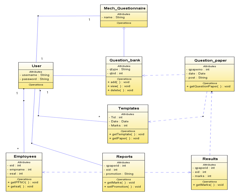
Class diagram for the System:

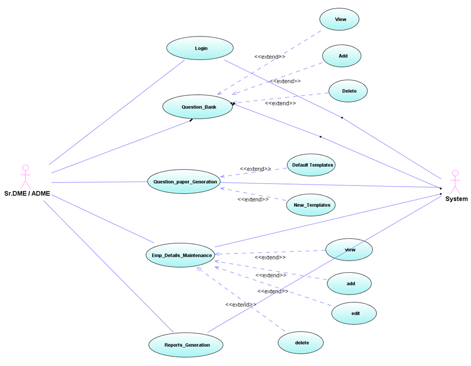
Use Case Diagram showing the actions of the administrator:

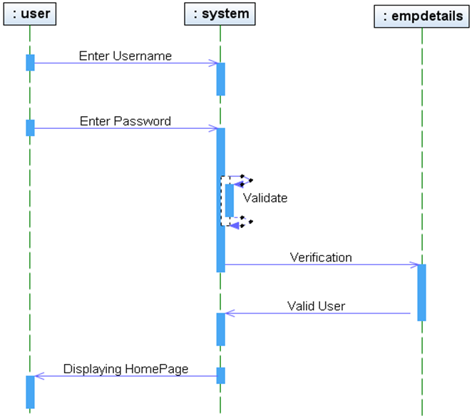
Sequence diagram for login to the system:

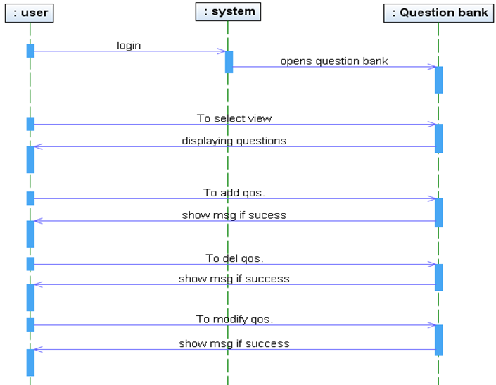
Sequence Diagram for Question bank:

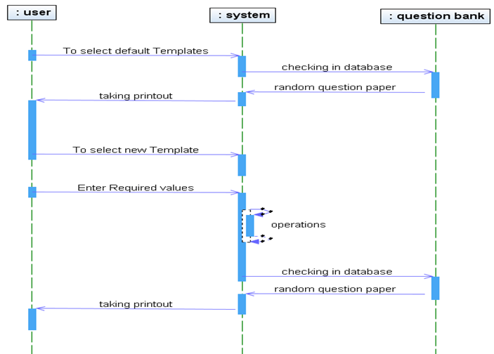
Sequence Diagram for Question Paper:

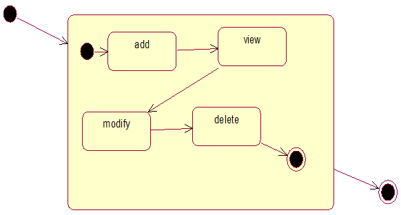
State Chart Diagram for admin object:

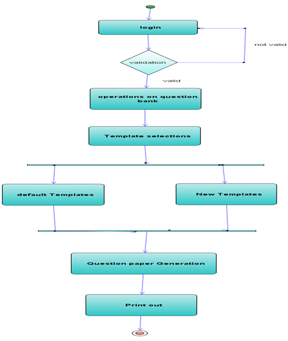
Activity diagram of the system:

Other Output Screenshots:

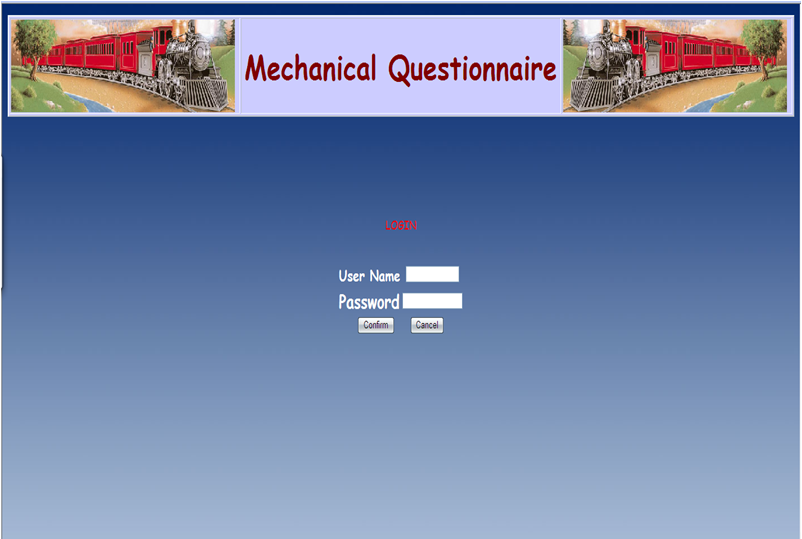
  • When user login to QB
  • Displaying QB
  • Viewing Questions from QB
  • Selecting to add Questions.
  • Adding Questions.
  • Deleting Questions.
  • Default Templates
  • Open/Save Q.paper in MS-Word
  • Question Paper Generator
  • Open/Save Question paper in MS-Word
  • Question Paper in MS-Word
  • Reports

Download Mechanical Questionnaire System Java Project Source Code