
Mechanical Approach:
Kinematics:
The GPS Navigation Robot Project we have designed to traverse on all terrains is on the concept of getting support from all the sides and having the ability to move ahead. The dimensions of the robot are 1600*965*810 mm. .
Design of Wheels and Motors:
The locomotion of bot is designed with six wheels so that the stability of the vehicle is high and moreover while climbing the steps or moving in rough terrain it will be able to have more support. Wheels of diameter400mm and thickness200mm are used. The wheels with V-THREAD profiles are selected to meet the desired need to move in all terrain. D.C Motors with specification of 40kg torque and 150rpm are designed to meet the desired speed and the load ratings. Similarly in total there are six motors one for each wheel hence each wheel will be having independent drive. The motors are placed in the wheel hubs supported by c-clamps.
Mechanism of Linkage:
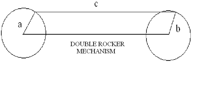
Kinematic of bot has three linkages in total. Each linkage supports two wheels. The front two wheels of each side are connected by one linkage and the rear wheels are connected by another linkage. Each linkage is designed on the concept of Double Rocker Mechanism. According to which there are two cranks connected to the main link. Similarly in this model the two C-clamps which are connected with the main link and the wheel acts like crank. Due to the presence of this type of linkages there is no separate suspension mechanism needed. At all point of times and at all positions always all six wheels will be touching the ground. This is the most advantageous point of having linkages.

In the above diagram A and B are the two cranks and c is the main linkage which is shown in the Double Rocker mechanism.
FIG: shows the linkage in connection with the wheel
Steering Principle:
Apart from six D.C Motors, four servo motors are placed in between the C-clamps and linkage except the two middle wheels. So the wheels can be turned in any direction. The wheels if properly turned to the required angle, the entire vehicle may completely turn in its position up to 360°.The directional gyro which is of electronic model when fixed in the correct axis can find out how much exactly the wheel’s angle is displaced. Hence when the wheel has been turned to the required angle the action from the micro controller can be given to cutoff the voltage to the servo motor there by removing its action. As each wheel has independent drive hence while turning the differential drive is obtained by giving variable supply to motor.
Material Selection of Chassis and Other Surfaces:
The chassis is the platform for electronic and mechanical tools. The chassis which should be light in weight as well as having high load capacity should be selected. Hence it was designed to use CNC Titanium or EPO resin.
The two surfaces which are extruded from the chassis are shown transparent in the diagram drawn in the pro-e modeling. This is due to the fact that both the surfaces are made of a transparent glass fiber made of carbon composite so whatever changes or deformations taking place could also be easily identified and rectified easily. Antenna is placed in the rear end, while the camera setup is placed in the front end. The camera setup has both stereo and C-MOS camera.