In order to define the traffic as well as the packet analysis the node as well as the service level settings are needed which are against the nodes and then the overall configuration is been followed further in order to explain the server and node level settings. As discussed earlier, there are 20 different types of mobile nodes along with the single wireless LAN server and then the nodes which are been configured towards the traffic analysis as well as the packet analysis is situated in the initial step. The steps required to perform this activity are explained below:
- Select the appropriate mobile nodes as well as the WLAN server
- Then after go towards the menu called protocol -à ApplicationsàIP
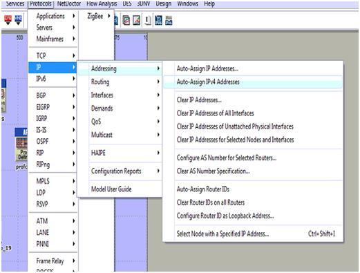
- Then after starting from the IP section select the option called Auto assign and then the IPV4 address through which the actual nodes as well as the WLAN server which are allotted are been sent to the alternate !PV4 address and the screen shot which explains this process is shown below:
The auto assign IPV4 address which are been selected for the entire process are been allotted to the different mobile node along with the wireless LAN server as explained in the below screenshot. The next step is to configure the mobile nodes as well as the server which is added towards the routing protocols. It is explained in the earlier section that AODV is been used for the purpose of desired routing protocol the applicable mobile nodes along with the WLAN server is used and the steps are explained below:
- The routing option is available to node levels or else to the server levels which are used to select the entire mobile nodes as well as wireless LAN server.
- Within the entire available nodes, a single node is selected as well as opened within the edit mode which can be performed by clicking on right button
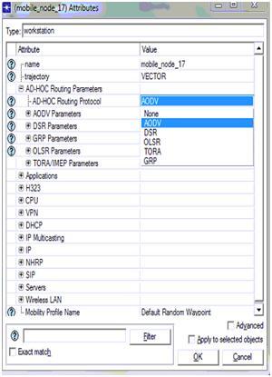
- Within this edit mode the quality such as Adhoc routing protocols are used which allows the server to display the entire list of the routing protocols towards the users starting from AODV scenario and the process will be explained in the below screen
AODV is been chosen from the available list in which the total number of routing protocols which are seen in the screen can select al the nodes along with the server that are against the AODV protocol and it can be verified in the form of selected objects shown in the screen displayed above. In the entire process if the routing protocol is all set to serve the traffic against the patters of routing parameters the nodes as well as the server will be totally against the applications and profile definitions process is explained below. The total application level settings are situated towards the nodes that are explained below:
- The total number of mobile nodes are been selected starting from the simulation networks and every node will be selected as well as edited in order to explain and define the total applications
- Within the node level qualities there are different types of options available such as application destination preferences and then the tab which is expanded can be used to explain the application requirements
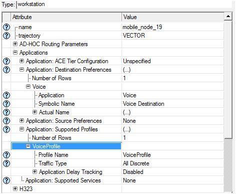
- The total number of tows that are explained as single nodes requires support to the voice applications that are created with in the below screen
Application destination preferences is set to one rows and then the voice application is selected for this row and the symbolic server name is given as voice such that this server will generate the required voice traffic and the corresponding packets across the network. Apart from the destination preferences now the application supported profiles are also set and in this context a single row is added to the section application supported profiles and voice profile is selected for this row as shown in the above screen. With this the node level application and profile definitions are applied to all the mobile nodes and the procedure followed to apply the same for wireless LAN server is given below
- Select the wireless LAN server from the network and open it in the edit mode
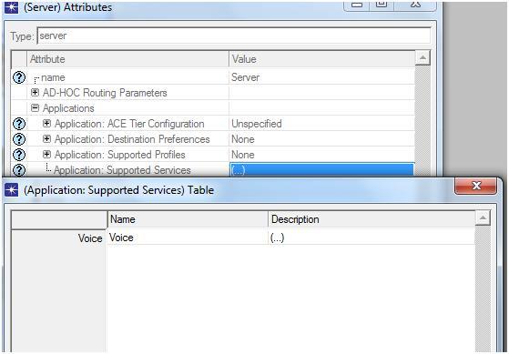
- There is an option like application supported profiles and expand this option to edit the profile settings for the wireless LAN server and the corresponding screen is as shown below
The above screen it can be identified that the voice profile which is been chosen as the main application facilitated and managed by the corresponding profiles the WLAN server will provide its support to the traffic that is distinct and then the voice profile will be generated and then the server will be capable of managing different types of the packets that are adjacent to the traffic. There is an alternate method which can be used to apply for the applications as well as the profile settings for the purpose of mobile nodes and wireless LAN server this particular process is known as deployment and these steps are explained in detail below:
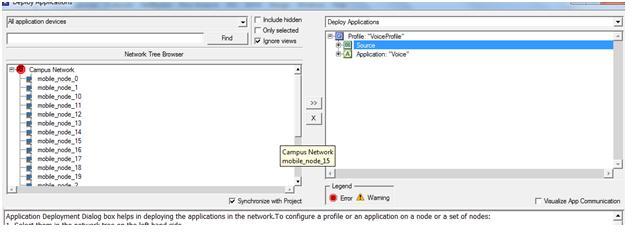
- The user should go to the protocol menuàApplicationsàDeploy in order to define the applications
- The new window is been displayed towards the user side and then the deployment process will be performed
- The entire mobile nodes are been submitted towards the source and then the WLAN server is been submitted towards the destination side and the example is given below
From the above screen it can be identified that the entire mobile nodes are submitted towards the actual source. A success message like consistency check pass is displayed to the users if the deployment is done in a right manner. With this the corresponding email application and email profile are applied to the 20 mobile nodes and the single wireless LAN server.

