Implementation and Analysis of Results
The Main Aim of this Distribution system Website is to explain in brief how the original Distribution system works actually in the networking world. This is mainly designed to explain how two systems will be connected to each other and how they behave in a network. The networking concept mainly revolves around two characters namely Server and Client. Each server can facilitate n number of client or in other terms each client should be mapped to a server.
In the design of this distributed system, three roles have been incorporated. The three roles in this design are explained as below:
Master Server: This is the main server which will accommodate all the servers. This is Main server under which there can be many servers mapped. There can be only one Master server in the network. This is the system at the highest level in a network model.
Server: This is the server which accommodates the client. This server should be under Master server. There can be any no. of these servers under a Master server in the network. This is the system at mid level in the Network Model.
Client: This is the system at the lowest level in any network model. Clients should be under any server that got mapped to the Master server.
The three roles assumed in this website. The login provided for this website was a role based login. Depending upon the login user’s Role the website will be acting differently.
This website facilitates to map a new client to each server. Each server can accommodate only limited number of clients(less than or equal to its capacity).Each server will have its own capacity pre-defined while creation of the servers itself. If the maximum capacity has reached the newly created client will be mapped to other server which is free (which doesn’t reach its maximum capacity).If no servers were found free i.e., if all the servers have reached their maximum capacities then the Master server should create a new server in order to accommodate the newly created client.
The design of the Distributed systems website was done in Micro soft Visual Studio 2010 using C#.net technology. The database used for this website development was Microsoft SQL server2008.The complete design and implementation of the website are explained clearly in the below section. This website mainly contains the following modules in it. In each module, initially the Connection component is declared and a connection string, which contains the Database connection properties, was fed. Since the Database used for this website is SQL server the connection we have created should be and SQL Connection.
The SQL connection string contains the database name, data source name, user ID and password. Once the connection was properly defined then the connection is to be opened so as to communicate with the connected database. Then the command is defined and executed over the database. Once the Command is executed, the Connection is closed. All the above-mentioned steps will be followed commonly in all the blocks of query
Master Server Module:
Master server module includes creation of new server when there is no free server under it. The privilege to create a new server was strictly restricted to the Master server. In addition to the creation of new server the Master server can also Insert Faults, View the status of the distributed system through Mobile Agent.
Creation Of Server: When there are no free servers available on the network,. i.e. when the maximum capacity of the servers was filled the clients cannot be created. In such cases the Master server is requested to create a new server under it such the newly created server can accommodate the Clients which are going to be created. All this concept is encapsulated in servermaster.aspx page. The code of which will be explained below.
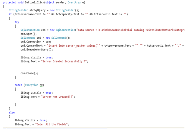
Fig: Code for the Create button in the Server Creation Page
From the screenshot 1.1(a), we can find out the code behind the Create button of the Server Creation Page. When the Master server enters all the necessary data for the creation of server like Server name, Server IP, Server Capacity and click on the Create button then this code will be called. From this block of code, a new record will be inserted into the server_Master table in the database.
When the Insert statement executes successfully then a message will be displayed to the User as “Server created successfully”. If the Insert Statement didn’t get executed then the Message will b “Server Not Created.”All the values entered by the Master Server Role will be captured as values for the insert statement. This Button click event will be completed only when all the fields were properly entered.
The “Server_Master” is the Table, which will accommodate all the servers. This table is treated as a Master server under which many servers can be mapped. Each server will have one Unique ID through which it can be identified along with the Server IP, Name, Capacity, Status. The detailed Description of the table and its columns is as below:
Server_Master: This table is the assumed as master server, which contains different servers, linked (inserted) in it.
- Server_ID: Holds a unique number for each server created. Server ID is an auto generated column starting from 1010.
- Server_name: Holds the name of the server.
- Server_IP: Holds the IP address of that server.
- Capacity: This column contains the maximum capacity of the server, means the maximum numbers of clients that this server can be mapped to E.g. if the capacity of a server is 3, then only 3 clients can be created under this server.
Insert faults:
Faults can be inserted only from the Master Server Login. The Faults in a distributed system as assumed as two types:
4.2.2(a) Linked server: By this mechanism the Master server can Deactivate the Link i.e. break the Link between any two system mapped in the Distribution Link. The two systems here mean that the Link between the server and any of the clients that got mapped to the server can be deactivated. If the link between the server and client was broken, the to and fro data movement will be stopped. No data transfer is possible between them until and unless the link is re activated again.
ON:
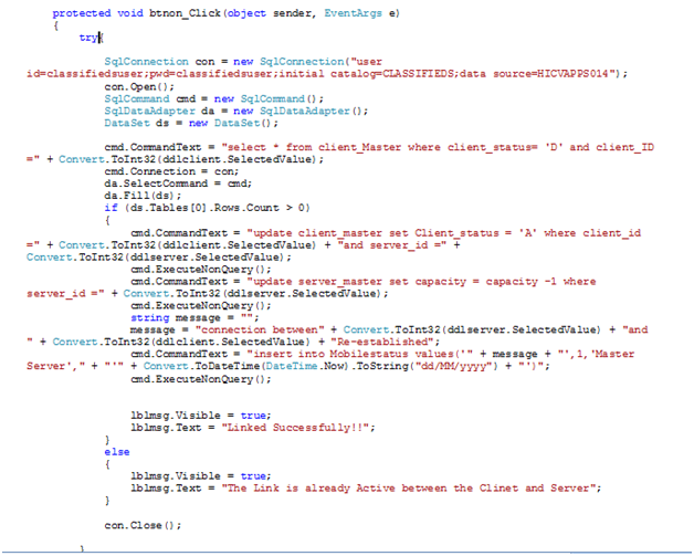
The code snippet for this module was as shown in the screen shot.
Figure showing the code behind the ON button in the Linked Servers.
Once the Master server selects the Server and the client combination on clicks on the ON button the code shown in the screenshot will be executed. In this block of code we are first checking whether the connection between the selected server and client combination was already ON or OFF with the help of the Select Query. If the record is with status ‘D’ it mean that the Connection is OFF.
Then only we will go into the condition and update the status of the connection between server and selected client as ON. The update of the connection status is done with the help of the Update Query on the Client_Master Table .The description of the Client_master table will be discussed below. If the Select query returns no rows it mean that the Connection between the server and selected client is already ON so need not activate the link again. Once the Connection between the Server and the client is Activated then same event will be logged in the database in mobile_agent table.
OFF:
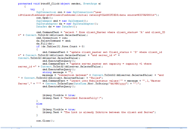
The code snippet for this module was as shown in the screen shot.
Figure showing the code behind the OFF button in the Linked Servers.
Once the Master server selects the Server and the client combination on clicks on the OFF button the the code shown in the screenshot will be executed. In this block of code we are first checking whether the connection between the selected server and client combination was already ON or OFF with the help of the Select Query. If the record is with status ‘A’ it mean that the Connection is ON.
Then only we will go into the condition and update the status of the connection between server and selected client as OFF. The update of the connection status is done with the help of the Update Query on the Client_Master Table .The description of the Client_master table will be discussed below. If the Select query returns no rows it mean that the Connection between the server and selected client is already OFF so need not De-activate the link again. Once the Connection between the Server and the client is De- Activated then same event will be logged in the database in mobile_agent table.
Client_Master: This table contains the information of all the clients available in this system.
- Server_ID: T his column contains the server ID under which the client was created.
- Client_ID: Unique number given to each client.
- Client_name: Name of the client.
- Client_IP: IP address of the client.
- Client status: This column indicates whether the client is active or inactive. Means, when a link between the server and the client is delinked then the client_status column will be changes.(A:active,D:inactive).
- Created_date: Date on which the client was created.
Distribution List:
From this Property of the Master server, it can make the complete distribution system to become In-Active or Active. If the distribution system is made In-active then all the tractions such as creation of clients, servers, sending data, receiving date will be completely stopped.Untill and unless the distribution system status is made active again no other tractions can be done. Soon after a role logins into the application, a message page will be displayed mentioning that the distribution system is OFF.
OFF:
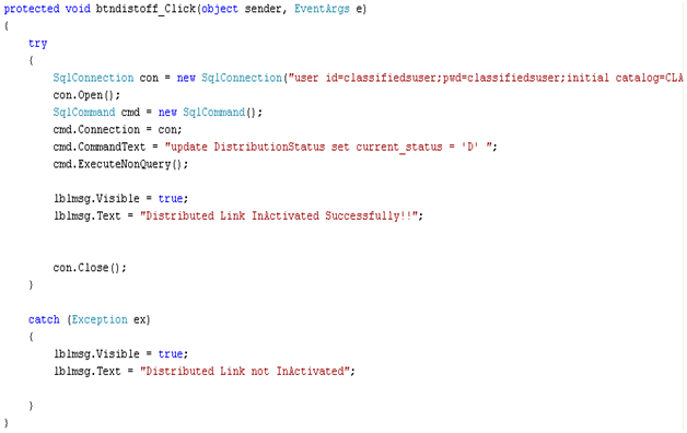
The code snippet for the OFF button of the distributed Link module is as shown in Fig:1.2(b-1)
When the Master server Clicks on the Distributed system there will be two button available for him. ON and OFF. If the master server clicks on the OFF button, the code in the screenshot will be executed. When the OFF button is clicked then the Current_status column in the Distrubutionstatus table will be modified as ‘D’, which means that the distributed system is made In-active. The distributionstatus table will be explained as below.
DistributionStatus: This table is created to maintain the status of the total distributed system. Whether it is ON or OFF.
- Current_status: Specifies whether the distributed network is active or not.
- Created_date: Date on which it was created.
ON:
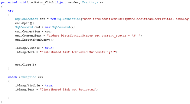
The code snippet for the ON button of the distributed Link module is as shown in Fig:(b-2)
When the Master server clicks on the Distributed system there will be two button available for him. ON and OFF. If the master server clicks on the ON button, the code in the screenshot will be executed. When the ON button is clicked then the Current_status column will be modified as ‘A’, which means that the distributed system is made In-active.
Mobile Agent:
When the Master server clicks on the Mobile agent button available in his home page thee this module will be invoked. From this module the Master Server can just view the different events that have been done on the Distribution System connections Such as activation (ON) and deactivating (OFF) status of the clients and servers, activation (ON) and deactivation (OFF) action sod the distribution links. Along with the status, he can also view the details such as by whom that event occurred, at what time was that event happened etc.
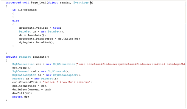
The code snippet of the Mobile agent button is as shown in the screen shot.
Fig : Showing the code binding the datagrid of the Mobile agent with log data
From the figure, it can be explained as this. When the Master server clicks on the Mobile agent button then he will be redirected to a new page called as “MobileAgent.aspx”. In the page load of this page, the code to fetch the Log data was written. The log data was fetched from a select query from the Mobilestatus table. The detailed description of the Mobilestatus table can be explained as below. The data fetched from the select query is captured in a dataset. This dataset is fed as the data source to the datagrid, which will display all the fetched data to the Master server in the form of a Data Grid.
Mobilestatus: This table contains the log status informing all the events happened in the distribution system.
- Event_occured: Mentions the description of the event what actually happed to the system.
- Done_by_ID: ID of the client/server who was responsible for this event to happen.
- Done_by_name: Name of the client/server who was responsible for this event to happen.
- Done on: Date on which this event occurred.
Client Module:
In this module, we will cover the creation of clients, sending data from client to its server or any other client that got mapped to the same server. In a similar fashion receiving the data etc. In the home page of this website there is a button named Create Client.
Create Client:
If any user clicks on the Create Client button then he will be redirected to a new page where in which he can enterer all the data and create a client. While creating a client it is important to map that client to a server. So while creation the system which check which server was free and will map the client to that server. If No server was found free then the client cannot be created until the Master server creates a new server.
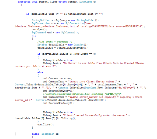
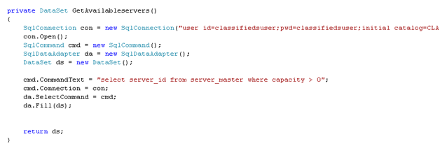
Once the users enters all the necessary data and clicks on the create button then the code attached in the screen shot will be executed. In this block of code the code will first check the availability of the servers with the help of “GetAvailableServer” the code of which is shown figure. The GetAvailabilyservers() method will select all the servers where the capacity is greater than 0 which mean that the servers were not full.
All the servers, which are free and retrieved from this select query, will be captured in a Dataset. If there are no servers in the dataset object then the client creation will not be possible. A message will be displayed to the user mentioning the same.
Fig: Code behind the create button of the Client creation Page.
Fig: Code for the GetAvailabilityServer() method ion client creation Page.
On the other side if there are any servers free then this new client will be mapped to one of the free server and a new row will be inserted into the Client_Master table which was discussed in the previous module. A simple Insert statement on the Client_master Table does this. Once the insertion is done, the capacity of the server to which this new client was mapped will be decremented by 1 in the server_master table using the update query. In the same way for each client, the server capacity will be decremented by one. Once the capacity becomes zero it mean that the server had become full and cannot accommodate any other client further.
Send & Receive Data Module:
This module completely deals with the data movement between one client and its own server as well as between this client and other clients, which were mapped, to the same server. During the data movements there are two components assumed. The Source and the Destination. The source will be onerously the client who logged into the system with his credentials. The destinations can be any one amount the Server of this client or any other client that got mapped to the same server. Means a client can send data only to its server or those clients, which were under the same server, but cannot send data to other servers or any others clients that were mapped to other servers.
When the client logins into the website, his main page will be different from that of the master server page. The client main page will have Send data button and Receive data button.
Send Data:
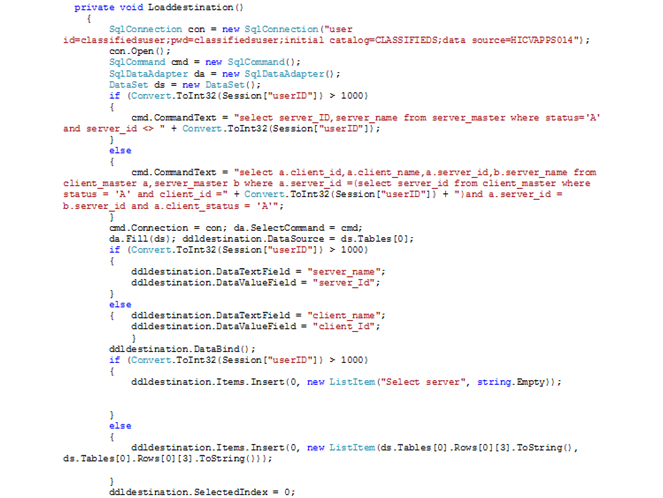
When the client clicks on the Send data button, the client will be provided with an option to select the destination to which this client is wishing to send the data. The binding of the Destinations in the dropdown list is as shown in the Fig 2.2(a-1)
Fig: code for the Loaddestinations() method.
LoadDestinations method implements a select query which will select the server of the Client which is sending the data and the other clients which got mapped to the server retrieved .All the data is captured in a dataset and this dataset is fed as a DataSourse to the dropdownlist containing Destinations.
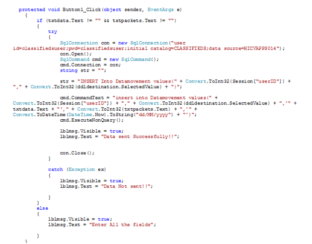
Once the Client selects the Destination to which it will send the data and enter the data in the textbox given the No. of Packets will be automatically calculated and will be shown in the No. Of Packets text box, which is a read-only control. Once all the data was ready to be sent such as Destination Name, Data, and No. Of Packets, the Send button can be clicked. Once the Send button is clicked, the Data will be inserted into the Data Movements Table, which will be described in detail next.
In the button click event an insert, statement will be written which will capture all the required fields’ data and will insert a new row into the Database in the corresponding Table. If the insert query is executed successfully then a message will be displayed to the user mentioning the success notification. If there is an exception while executing the Query then the same will be captured in the Catch Block and the insert statement will be rolled back. The code for the Button click event is shown in the figure
Fig: code for the Button Click method.
Receive Data:
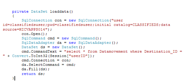
When the client clicks on the receive Data button in his main page after login, he can view all the data he received from various sources. The Data received by this client will be shown in the data grid format. The data received by this client can be obtained by using a simple select query on the table Datamovements. The data where the destination is this Client will be fetched from the datamovement table. Therefore, the Login client ID is saved in a session Variable and this is used fro the filter condition in order to fetch only the data received by this client. The code used to select the data received by this client is shown in the figure Fig:2.2(b)
Fig: code used to get the Data received by a specified Client.
The Data movement table, which is used in send and receive data module, can be explained as below:
Datamovement: This table contains the information related to the data moving to and from between the client and servers.
- Source_id: The source(client/server Id) from which the data is sent.
- Destination_id: ID of the client/server, which received this data.
- Data: The actual data moved between the source and destination.
- No.of packets: Specifies the number of characters moved (if data=”hello” no. Of packets will be 5)
- Received_date: Date on which the data was moved.
Server Module:
In between the Master Server and Client there will be one more role named the SERVER. The server is the one, which is mapped to a Master Server and will accommodate Clients under itself. The Server role is just permitted to send and receive Data. Each server can send data to other servers and receive data from other servers as well as the client under this server. The whole logic for the send and receive module of this server role will be same as that of a client role which was already discussed in the previous module of the client.
All these operations such as sending and receiving data, creation of clients, creation of Server under Master server, Insertion of Faults will be allowed only when the Distribution Link is Active. When the Distribution list is OFF no operations listed above will be done. When the Distribution System link is OFF, Master Server is the one who will have access to ON the Link. Until and unless he activates the Link, the Master server will also be blocked to perform any of its normal functions. So whenever a user logins into the system, the system will first check whether the Distribution Link is ON or OFF.
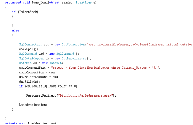
The code shown in the below figure explains how this logic was been implemented in this website. This check can be done by using a select query on the DistributionStatus table will will be explained below. If the Current_Status column in the DistributionStatus table is ‘A’ then it means that the Distribution system Link is ON. So all the operations can be performed. So the select query will fetch the record if the status is ‘A’.
If there are no records fetched for this select query ,it mean that there are no records with Active status, which mean the distribution link is OFF. So the dataset is checked for any rows. If the Dataset contains 0 rows in its table then the user cannot enter the website, instead he will be redirected to a page where the Message will be displayed to the user mentioning that the Link is OFF. If the user who was trying to enter into the website was a Master server then he will also be provided by a button, which can allow him to ON the link again.
Fig: showing the code for checking the distribution link status in Page_Load event.
Paper Submitted & Written by Sathish Nagarajan

