Wireless Equipment Control Using Microcontroller

In our project wireless equipment control using microcontroller AT89C51, we implemented a wireless based control circuit for efficient operation of the industrial equipment. The proposed circuit is capable of switching four devices at a time in required time based on the time interval set by the user in the transmitter.

Wireless Equipment Control Using Microcontroller block diagram

The data is transmitted based on the wireless RF communication, using TRX -434 RF transmitter modules, RX-434 radio receiver module.

Transmitter section:

The transmitter section consists of 8-bit AT89C51 microcontroller, LCD module, and encoder IC (HT12E).

Receiver section:

The receiver circuit had 12v dc supply battery with 5v dc regulator, RX-434 radio receiver module, and HT12D decoder for demodulation of received signals, IC CD4519 multiplexer and ULN 2003 relay driver.

Youtube video link to view presentation ( circuit diagrams, pcd besign)

http://www.youtube.com/watch?v=xGiLnJtP7hc&feature=youtu.be

Software programming:

  The micro controller programming is done Keil C51 using the embedded c programming language, the compiler is used to convert the high level language into machine level language. The programming is an assembly level language based on embedded C.

Circuit assembly:

The total circuit components are assembled on the printed circuit board. The process of fabrication is done as follows, firstly prepare a circuit layout and draw it on the copper clad board – drill it for terminal holes – do etching and cleaning process for excess particle removal – Soldering – testing.

Download Wireless equipment control using microcontroller Project Report code

Applications:

  • Used for controlling house electrical equipments and prevents form their damage under over current conditions.
  • Used for controlling the industrial equipment and power generation equipment under overload situations.

Used to implement controlling mechanisms in labs.

Heart Beat Monitoring System

In recent days wireless patient Heart Beat monitoring system Project are gaining high reputation in medical field in terms of providing a reliable and accurate diagnosis for the patient. Here in this project Report “Heart beat monitoring by GSM technology” we implemented a micro controller based heart beat monitoring system based on GSM module.

These systems can easily sense the abnormal conditions of the patient located at remote places by means of a GSM modem. In order to perform these operations we need heart beat sensor, GSM modem, P89V51RD2 micro controller for controlling the auxiliary elements of the circuit.

Project Category:

Microcontroller and GSM Technology

Embedded systems:

Embedded systems are abbreviated as the computing systems embedded on a single integrated chip. These are special purpose computing systems design to implement specific tasks based on real time constraints.

Youtube video link to view ppt , circuit diagram

http://www.youtube.com/watch?v=vybx3PjYu1Q&feature=youtu.be

Power supply circuit:

The power supply circuit consists of an assembly having step down transformer -rectifier unit – smoothing filter – LM7805 voltage regulator for purpose of getting 5v regulated dc from 230 ac supply.

Download Heart Beat Monitoring System Project Report

Heart beat sensor:

The senor concentrate on the flow of blood in the finger the LED emits light with specific intensity on one side on the other side the change in light is measured by the light dependent resistor and detects the heart rate based up on the amount of change in blood in the finger.

Automatic Street Light Control Project

In Automatic Street light control project for on & off using light dependent resistor, we developed an automatic energy efficient device using micro controller based on light dependent resistor.

In recent day’s energy efficient control systems are gaining importance due to the implementation of embedded systems in the field of automation technologies, the key elements of the embedded systems are micro controllers.

Need of automatic sensing devices:

  • To conserve the wastage of electricity.
  • Limiting usage of power in unnecessary time.
  • To maintain accurate intervals of time in switching street lights.

Youtube video link to view block diagram, circuit diagram, components list.

http://www.youtube.com/watch?v=EDG1oZ_kdFg&feature=youtu.be

Operation:

The streets are automatically switched on when the light intensity falls below the threshold value, and the intensity of the light is sensed by the light sensors i.e. light dependent resistors, light dependent resistor exhibits high resistance under sufficient light and acts as an conductor i.e. low resistance path in times of low light intensity periods. This entire process is monitored by a micro controller based on the signals from the light dependent resistor.

Hardware components:

  • Micro controller – low power high performance 18F452 Microcontroller is used in the project which manipulates the circuit based on the light dependent resistor.
  • Power supply circuit – a combination of step down transformer, bridge rectifier, filter, regulator used for getting 5v regulated dc output.
  • Display unit – 16×2 LCD modules is used in this project as an output device.
  • Triggering circuit – relays are used at the output terminals of the micro controller in order perform the on/off operations for the circuit.

Download Automatic Street Light Control Project Report

Load monitor and Breaker with Digital Display using Microcontroller

In recent days the application of micro controllers are increasing in electrical equipment protecting devices. Electrical systems are allowed to operate without any proper control system, so keeping this in mind we implemented a “Load monitor and Breaker with Digital Display using Microcontroller “  to protect the electrical systems from over currents.

The basic requirements of the protecting device are to monitor the changes in the current, voltage, frequency of the power system. For that we make use of micro controller in sensing the varying conditions and a protective relay is operated for protecting the network from un wanted over currents.

Youtube video link to view block diagram

http://www.youtube.com/watch?v=XJKpHVqWr0w&feature=youtu.be

Project description:

The over current protection system uses an PIC micro controller, whenever the current in the main lines crosses a particular value the micro controller causes the circuit breaker to trip the circuit.

So firstly we need to monitor the load current so for that we use a current transformer whose primary is connected to the load terminals and its output terminals are converted into dc by using an rectifier and filter and it is converted in to digital pulses by the A/D converter, and then this digitalized pulses is fed to the micro controller, if this signal crosses the normal value it trips the circuit by passing signals to the relay circuit.

 Download Load monitor and Breaker with Digital Display using Microcontroller Project Report

Hardware of the protective system:

The hardware i.e. the main components of the proposed system are,

  • Sensing circuit – sensing circuit included current transformer i.e. current sensor, relay and circuit breaker.
  • Control circuit – PIC micro controller interfaced with the secondary of the current transformer.

Logic Gate Emulator ECE Mini Project

Logic Gate Emulator ECE Mini Project mainly developed for Electronics final year students. This Logic Gate Emulator is the device that is used for emulating the microcontroller logic gates like NOT OR, AND etc. this device has different switches that is used to select the device.

They use SPDT switched for the logic gates and these device have two inputs and one output. They LED as the display for the output. Separate LEDs are provided for the separate gates and they glow for the corresponding gate. The whole operation performed by the microcontroller.

Logic Gate Emulator ECE Mini Project Block Diagram:

Logic Gate Emulator ECE Mini Project

8051 Micro Controller Description:

Microcontroller is the single chip based device that contain memory, CPU, RAM and ROM. They also contain clock and they control the input and output signals. They are also called computer chip.Every device and products today work on the microcontroller; they are embedded with millions of products. They are used in the appliances and even in the vehicles. A single car has more than 50 microcontrollers.

AT89S52: they are the 8 bit microcontroller with 8k bytes of the available memory flash memory. They are high performance and low power consuming microcontroller. They are developed using the Atmel technology that create nonvolatile memory and they are compatible with the standards of industries. They uses flash memory, it means that they can be re-programmed.

They are made up of monolithic chips. They are less costly and flexible. They have 256 bytes of RAM and they have 32 inputs and output with timer that is based on the watch dog timer. They have two data timers that have three 16-bit timers, and six vectors interrupt architecture. They have serial port that is full duplex and oscillators and clock circuitry. They are based the static logic for performing operations. They have Idle that stops the CPU but the RAM, timers and counters are still working.

GSM Based Home Security System Project B.tech ECE Idea

Project Title:

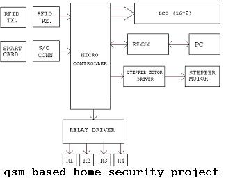
GSM Based Home Security System Project

Introduction to GSM Based Home Security System Project:

When we talk about the security the one thing come in mind that whether our home is secure or not. It is must to secure our home first then look at other things. Our home has always important documents, money and other precious things, that need to be protected from the intruders or thieves.  We also need to protect the home from fire and gas leak as they can also destroy our home.  We can use security device at our home that will warn us from any harm by alarm or sending SMS to cell. We can use 8051 micro controller or 89s52.

GSM Based Home Security System Project Block Diagram:

GSM Based Home Security System Project B.tech ECE Idea

They are low power chips. They are high performance chips with 8 bit and they is flash memory for storing data.This flash memory allows them reprogram when required. Flash are made up of monolithic chips as they are highly flexible and loss cost. They consist of 32 I/O lines, timers, pointers, oscillators, and clocks etc.

For this microprocessor we use the software called Kiel u- version. This provides tools for the development of the software of the 8051. With the help of this we can generate embedded applications. They use the protocol command named as AT command. They receive the message comes from the phone, then decode the SMS, authenticate the number. Then use their ports to control the specific appliances and after the operation send the feedback to the users for the confirmation.AT command sets are used for the GSM service to connect the device with the mobile phones.

Functions: they have internal RAM and ROM.  Input output ports for programming, timers and counters, 8 bit status words. They contain two 16 bit timers with 4 banks of registers. The RAM used has the memory of 128 bytes. 80 bits are assigned for the general purpose of data memory.

ECE Project Abstract on ZigBee-Based Vehicle Access Control System

The system of vehicle access control is one of the most important sub-system of the residence section of the intelligentized department. Today there is an urgent need of emphasis on safety of property and personal property, control of vehicles, authorization of access and vehicle management via the use of computers.

This document also describes a control system on a set of vehicles that is based on the technology of ZigBee wireless. The co-ordinator of ZigBee wireless in this system along with its nodes are installed at the entrance respectively. Together they form a ZigBee wireless network sensor. The entire structure was introduced in this document along with the software design and platform of the hardware. The performance test as well as the state of the implementation exam this system is the most suggestible option for everyone.

The ZigBee WSN technology is used in these designs and it helps to realize the management of wireless and dispatch system of the access of vehicles. This system also works well with the testing and demonstration thus providing good results. In the usage of C51RF-3-ZDS this is the most ideal option. There are various advantages of this system:

Accessing of vehicles to the entrance

The introduction of transmitter in the car helps to send informations that are related with the help of the module of the radio transmitter in CC2430 chip to the access control office receiver. When the receiver gets this information successfully  it passes the data for decoding. The control system will then receive the same message and store it in its database. The query of the data in the database can be made by the manager including number of the driver, plate number of the license and etc. Although there are yet several changes that a re need to be made in this system but it had already passed the test with good results.

RFID-based Autonomous Mobile Car Project Abstract for ECE

Radio Frequency Identification (RFID) framework is looked upon as one of the top ten imperative advances in the 20th century. Modern mechanization provision is one of the crux issues in advancing RFID. Thusly, this paper plans and enables a RFID-based self-governing portable auto for broadly requisition of RFID frameworks. The microcontroller of Microchip PIC18F4550 is utilized to control the independent versatile auto and to correspond with RFID bookworm. By archiving the moving control summons for example turn right, turn left, accelerate and speed down and whatnot.

Into the RFID tags already and staying the tags on the tracks, the independent versatile auto can then peruse the moving control charges from the tags and fulfill the correct activities. Because of the benefit and non-contact trademark of RFID frameworks, the suggested portable auto has important potential to be utilized for streamlined mechanization, products transportation, information transmission, and unmanned medicinal nurturing and so on? Test effects exhibit the validity of the recommended versatile auto.

RFID framework is looked upon as one of the top ten paramount advances in the 20th century. Undoubtedly, the modern mechanization requisition is one of the crux issues in improving RFID. The usage of RFID mechanics is novel and may upgrade the existed mechanization framework. A RFID-based self-governing portable auto was finally planned and achieved in this paper. By composing the moving control summons into the RFID tags heretofore and staying the tags on the tracks, the self-governing portable auto can then peruse the moving charges from tags and fulfill the correct activities.

Test outcomes exhibited the validity of the recommended framework. Some more exhaustive and propelled control systems and their comparing control summons can moreover be outlined and saved in tags then after that utilized to control the auto exactly, the examination can be explored in the fate. Radio Frequency Identification (RFID) framework is looked upon as one of the top ten essential advances in the 20th century. Consistent with the examination of the AMR Research, the readiness for utilizing RFID tags overtakes 85% dependent upon 500 USA adventures.

Speed Factory Automated Checkpoint Log System for Bike Races Microcontroller Project Report

Adding RFID is the main object of this project for every participant of biking in rally and to set up a micro controller that is based on the readers of RFID at various checkpoints all along the route. The boards of micro controllers are equipped with RRTC or real clock time to keep a track of the time and EEPROM helps to maintain the cross timing for each and every bike.

These data are later used to develop units of micro controllers that can be transferred to a database that is centralized via the serial that comes with every board of micro controllers. The software of the computer can then be used for generating time based maps, lap records, analysis report results of races and graphical results.

The boards that are based on the micro controllers are present at the various check points and they are equipped with the RFID reader that is used for reading informations from tags of RFID that are used in each and every bike participating in the race. RTC is used to handle the time and data at the time of power loss and EEPROM to save the data of croosing as well as the time.

To maintain the system status a display is used. Low cost check points can also be used in the system and they need to be maintained on a regular basis. These are available widely for collecting informations from all the available check points on a PC that is connected via the serial link one by one. A port connector is provided for all the boards of micro controller that are present at the check post for the message transmission to the PC. The EEPROM include a wide space and is used for storing of information  about the races for several days and weeks. Transmission of messages can take a few minutes and it will be followed by the merging of results.

MicroController Based ECE Project Report on Smart Junction with Circuit Diagram

Introduction to MicroController Based ECE Project on Smart Junction:

With the economic growth of the global transportation acts as an instrumental and it happened since the start of the early civilization that is known to man. The major impact on the economy of the country happened due to the management of traffic. The discovery of Information and Communications Technology or ICT led to an increased production management and it happened in the era of the Industrial Revolution. This also results in enhancement of various new improvements that is introduction of cheap vehicles and construction of roads.

Over the last few years the enhancement in the population of the urban civilization and the ownership of the vehicle has also lead to an increase in the congestion of traffic on roads in the cities all across the globe especially in those areas that are populated densely, eg: India. Therefore it leads to the integration of the ICT with the infrastructure of transportation and vehicles that acts as a background for the Intelligent Transportation Systems. This system is here to deal with the congestion of traffic problem throughout the world and it will also make the system more efficient.

Artificial Intelligence is used by ITS for the automation purpose. ITS is also included in the technologies of vehicle detection as well as used for actuated control of signal of vehicles. The term actuated control means the signal dependencies on the split phase, duration time and phase sequence on the actuations of the vehicles that are registered at the detectors as other sensors meant for traffic as well as their response variance according to the present traffic demand.

Moreover, it is a kind of traffic responsive control system where the received signal inputs reflect the conditions of the present traffic conditions. It also uses this data to create the timing plan for crossing. This can create optimally as well as automatically. The vehicle detectors are the source for the receiving of these signals that are located at the crossings. It modifies the time plan from its default settings accordingly.