Department Announcement System ECE Project Abstract

Abstract

In most of the institutes, announcements are coming under the major problem. A universal announcement by speakers is mostly deployed in most of the institutes, but there are cases when the announcement needs to be done for a particular classroom or for a particular person.

In that case, such a universal system will not be helpful. One resolution of this problem most of the institutes adopt is deploying one universal system and a separate system for each room and then place people to handle the entire control system.

Though this resolves many issues, it increases the cost of the entire control unit when you have to be dependent on human resources. Automation is one of the most thriving of today’s technology through which many organizations are cutting costs on Human Resources and utilizing human resources in more innovative and productive works.

So here for this issue also we have come up with automating the entire process of announcement where a pre-recorded voice will be played for every announcement in the institutes.

Block Diagram:

Communication channel box :

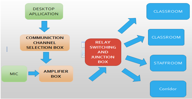
In this communication channel box signals from the desktop will be received to microcontroller and microcontroller will send a signal to relay driver  IC (ULN2803)  to switch the relay.

Relays —— SPDT.
Voltage —–12V

Purpose of the relay is to channelize the sound for each classroom.

Amplifier box

This box will receive the signals from mic where we speak and sound is amplified and sent to relay channel junction box.

Advantages

  • Human effort is reduced.
  • Time to convey the things can be done in a more faster phase.
  • They won’t be any communication gap with this setup.
  • We can communicate in multiple classrooms at one time.
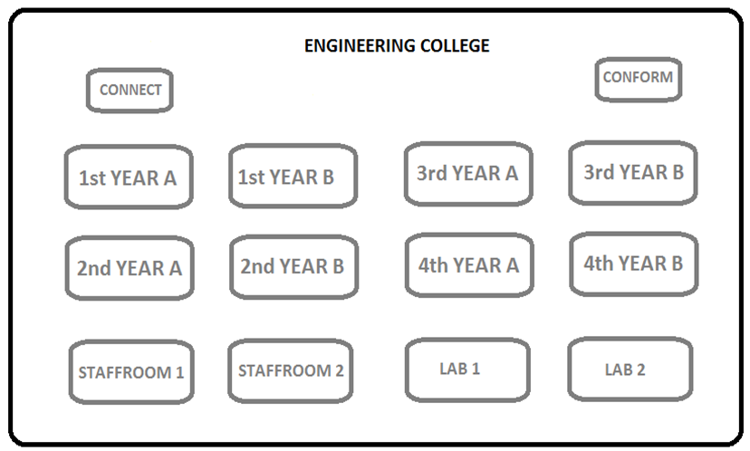
  • We can know the delivery report of a speech delivered to the classroom or not with help of feedback button in each classroom.

Automatic Touch Screen Testing Machine Project Synopsis

Content:

  1. Abstract
  2. Electronics circuit and embedded systems
  3. Mechanical design.
  4. Microcontroller program
  5. Android app

Abstract

Designing and developing an automation process for testing capacitive touch screen of mobile, there will be android app installed in mobile which displays few color blocks on lcd screen when capacitive touch pen touches the particular color blocks on lcd screen with help of automation process with X,Y and Z-axis movement by holding capacitive touch pen on Z-axis, when capacitive touch pen touches color blocks on lcd screen in this process color block on lcd screen will change if its touch sensitivity is good else the block color will remain same and feedback from android mobile is taken for evaluating performance of touch screen and feedback is displayed on LCD screen.

Specifications

• XYZ axis router setup.
• Atmega 2586 Microcontroller board.
• DC motor driver L298.
• 12V/5A regulated supply.
• Hi-tech 645MG Servo motor z-axis movement.
• 2 DC motors for x-y plane axis movement.
• 2 DC motor encoders 16bit.
• Capacitive pen and its holder.
• 20X4 LCD Display.

Electronics circuit and embedded systems

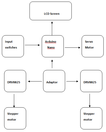
In this Automatic Touch Screen Testing Machine project we are Arduino nano board which consists of Atmega328 microcontroller with 2KB RAM and 64 KB flash memory this board will act as control unit which gives signals to DRV8266 stepper driver motors and 16 X 2 LCD screen, we have 4 input switches to select menu options all these are interfaced with Arduino nano motherboard.

List of components used in this project.

• Arduino nano 1no.
• DRV8266 stepper motor driver 2nos.
• Nima 13 stepper motos 2nos.
• Servo motor 90G 1no.
• 16 X 2 alphanumeric LCD.
• Input switches.
• Connectors and wires.
• 12V / 2A Adaptor.
• Dotted PCB.
In our Automatic Touch Screen Testing Machine project, we have used dotted PCB for interfacing.

Block diagram of electronics parts

Circuit working operation

We are using 12V / 2A adaptor for powering our circuit board Arduino nano and DRV8825, Arduino nano plays a major role in this Automatic Touch Screen Testing Machine project.

Wi-Fi Based Water Level Monitoring & Motor Pump Controller

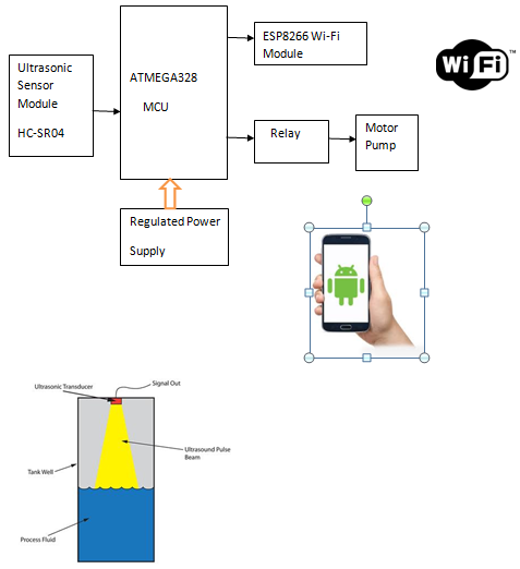
This development is used to overcome the pressure of physical process of water pump motor control. The purpose can be divided in sensing unit and control unit. The sensing unit is a contactless ultrasonic sensor which can evaluate an obstacle up to 4 meters. In our case,

In our case, an obstacle for the sensor is water surface level. The ultrasonic digital sensor section is interfaced with the microcontroller. The control unit is the motor on/off the circuit.

Microcontroller used in this the project is ATMEGA328.The water level is monitored remotely using wi-fi communication with the android app. We are using ESP8266 module to transmit data to remote end. The water pump motor is connected through relay driver. The motor pump can be turned On / Off using android app.

Software:

• ARDUINO IDE
• EMBEDDED CPP CODE
• PROTEUS SIMULATOR

Hardware:

1. ATMEGA328 Microcontroller
2. Ultrasonic sensor Module HC-SR04
3. Relay Driver
4. Water Motor Pump
5. ESP8266 Wi-Fi Module

BLOCK DIAGRAM:

QR Images Optimized Image Embedding in QR Codes

Existing System:

In the existing System, the concept shown was to how to embed an image with a QR Code, which can be implemented much easily with the currently online tools then the explained algorithm.

Proposed System:

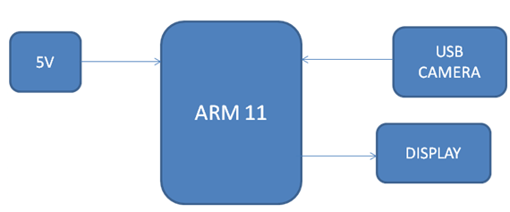
In the QR Images Optimized Image Embedding in QR Codes Proposed System, we are going to develop a new approach GUI based algorithm to read the data embedded into the QR Code using the open source tools live USB camera will continuously stream the video with the data recognition algorithm running background, whenever to the system a QR Code is displayed in front of the Camera, it will decode the data of the QR image onto the screen.

BLOCK DIAGRAM

Hardware:

Raspberry pi (ARM11), USB Camera

Software:

Raspbian OS, QR Image Recognition algorithm

Applications:

Data hiding, Security, advertisements.

Advantages:

1) Developed on ARM 11 Based processor, which runs at high speed due to which no data lapse will be done
2) Low power consumption and high accuracy.

Real Time Hand Gesture Recognition for Computer Interaction

ABSTRACT

The Real Time Hand Gesture Recognition system presented, uses only a webcam and algorithms which are developed using OpenCV computer vision, image and the video processing algorithms.

Existing Work:

The Existing work carried was done a PC based MATLAB software, where it has readily available all the algorithms and such system is not used to full extent in embedded side.

Proposed Work:

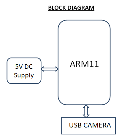
Proposed Real Time Hand Gesture Recognition for Computer Interaction work will be carried out on Linux based single board computer with ARM 11 architecture. This board will be ported with Raspbian Operation System and OpenCV Image processing Library. Using which will design an algorithm such that the system will identify the finger tips and count them how many fingers have been displayed.

BLOCK DIAGRAM


Hardware:

ARM11, USB Camera, Power supply.

Software:

OS: Embedded Linux, Language: C/ C++, IDE: Qt Creator, Opencv.

Applications:

Computer Interaction, Gesture recognition based control

Advantages:

• Elimination of external hardware like mouse
• Easy to access and control appliances using gestures.

Android Based Voice Controlled Notice Board

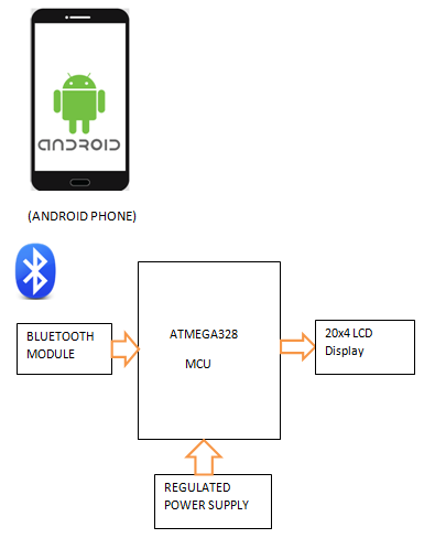
We are using voice recognition Android App for updating message on 20×4 LCD with the help of Bluetooth module HC-05. The android app converts speech into text using google speech to text conversion.

We are sending text data using mobile phone which is received by Bluetooth module and given to microcontroller. The microcontroller used here is from Arduino UNO(Atmega328) which sends the same message on it.

Software:

• ARDUINO IDE
• EMBEDDED CPP CODE
• Proteus Simulator

Hardware :

1. ATMEGA328 Microcontroller
2. Bluetooth Module
3. 20×4 LCD Display
4. Regulated Power Supply

BLOCK DIAGRAM:

Arduino Based Weather Station Monitoring System

The objective of this Arduino project is to build weather monitoring station. In this project, we are measuring temperature, Humidity, atmospheric pressure etc.

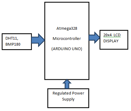
The main features of our project design are that it is small in size, low cost, less weight, less power consumption etc. We are here using DHT11 Sensor which can measure physical parameters temperature, humidity. BMP180 Sensor from Bosch is basically a pressure sensor.

We are here using Arduino board which has Atmega328 microcontroller to process data. It displays the result on 20x4LCD. It shows parameters such as temperature, humidity, pressure etc. It plays important role in weather stations.

SOFTWARE :

• ARDUINO IDE
• EMBEDDED CPP CODE

HARDWARE:

1. Atmega328 Microcontroller (Arduino UNO)
2. DHT11 , BMP180
3. 20×4 LCD Display
4. Regulated Power Supply

BLOCK DIAGRAM :

Electronic Siren ECE Project

We the undersigned had certified and acknowledge the successful completion of the Project Report entitled ” ELECTRONIC SIREN

We certify that we have examined and recommended to Government Technological College for Under-Graduate studies for acceptance the project entitled “ELECTRONIC SIREN” submitted by in partial fulfillment of the requirements for the Diploma of Engineering.

The 555 IC Circuit

The 555 monolatic integrated circuit timer was first introduced by Signetis Corporation in 1927 u8sing bipolar technology. It quickly became an industry strand for, timing and oscillation functions. Many Manufactures produce a version of a 555 IC, some in the CMOS technology. The 555 is a general-purpose IC that can be used for precision timing, pulse generation, sequential timing, time delay generation. The 555 can operate in both astable and monostable modes, with timing pulse ranging from microseconds to hours. It also has an adjustable duty cycle and can generally source or sink output currents up to 200m.
Basic Operation

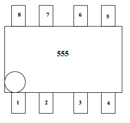
The basic block diagram of the 555 IC is shown in Fig. The circuit consists of two comparators which drive an RS flip-flop, an output buffer, and a transistor that

discharges an external timing capacitor. The actual circuit of an LM555 timer is also shown.

The RS flip-flop is a digital circuit that will be considered in a later chapter. Here, we will only describe the basic digital function of the flip-input with voltage references set at (2\3)V by the voltage divider comparator output goes high, producing a high output at flip-flop terminated Q. This turns the discharge transistor on and an external timing capacitor starts to discharge.

The output state of the 555 IC is driven by output Q of the RS flip-flop. This output is usually a totem-pole circuit, or a simple buffer, and is generally capable of sourcing or sinking 200mA.

An external reset input to the RS flip-flop overrides all other inputs and is used to initiate a new timing cycle by turning the discharge transistor on.
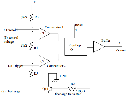
Fig. Basic Block Diagram 555 IC Timer Circuit Diagram, LM555 Timer Circuit

RESISTER

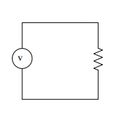
A component is used for its resistance. In the past, most resistors were manufactured from carbon composition, a baked mixture of graphite and clay. These have been almost completely superseded by carbon or metal film resistor. Wire-wound resistors are used for comparatively low values of resistance where the precise value is important, or for high dissipation. They are unsuitable for RF use because of their reactance.
CAPACITOR

A passive circuit component is a capacitance. A capacitor is formed from a pair of conducting surfaces separated by a layer of insulator. A capacitor made from a pair of parallel conducting plates of area S separated by a distance d, with the gap between the plates filled by a dielectric of relative permittivity E, will have a capacitance C given by

C = εrεoS d
where εo is the permittivity of free space.

A component that converts an electrical signal into light signal can be injected into the Fiber.

TRANSISTOR
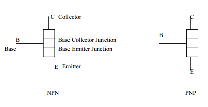
The bipolar junction transistor (BJT) is constructed with doped semiconductor regions separated by two PN junctions. The three region is called emitter, base, and collector. The physical representation of the two types of bipolar transistors are shown in Fig; One type consists of two n regions separated by a p region (PNP)and the other consists of two p regions separated by an n region (PNP).

The PN junction joining the base region and the emitter region is called the base-emitter region. The junction joining the base region and the collector region is called the base-collector junction.

Fig. Standard Bipolar Junction Transistor (BJT) Symbols
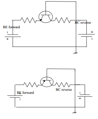
Fig. Forward Reverse Bipolar Transistor

The directions of the current in on NPN transistors are as shown in Fig; These diagrams show that the emitter current (IE); the same of the collector current (IC)and the base current (IB).

RECTIFIER

Fig. Block Diagram of Rectifier Circuit

The power supply consists of a transformer, receiver, and filter circuit. The transformer is probably one of the most useful electric devices. The transformer provides a simple means of changing an ac voltage or current from one value to another. A simple transformer consists of two coils (windings). The coil connected to the source is called primary winding and the other one is called the secondary winding. The coils are insulated from each other and from the core.

If a transformer receives energy at a low voltage and delivers it at a higher voltage, it is called step up transformer. When a transformer is supplied some lower voltage, it is called a step-down transformer. We used a step-down transformer in the circuit.

For an autotransformer, the secondary winding is actually part of the primary winding. The rectifier circuit is the process of converting an alternating (ac) voltage into one, that is limited to one polarity.
Rectifier circuit that contains diode is called rectifier diode. The diode can pass current easily in one direction only.

Rectifier diode can be used to charge a RESERVOIR CAPACITOR in order to obtain smooth DC. The rectifier circuit is classified as half-wave and full-wave rectifier.

The output voltage appears only during the positive cycle of the input signal, the circuit is called a half-wave rectifier.

A rectifier output voltage occurs during both the positive and negative cycles of the input signal, this circuit is called a full-wave rectifier.

Full-wave rectifier consists of

(a) Central-tapped full-wave rectifier; and

(b) Bridge full-wave rectifier.

We used Bridge full-wave rectifier.
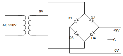
Fig. Schematic Circuit Diagram of Rectifier

Filter circuit provides a constant voltage to a load. The capacitor used in the filter circuit.

DIODE

The diode can be made of either two of semiconductor materials, silicon, and germanium. Power diodes are usually constructed using silicon and germanium. Silicon diode can operate at higher current and at higher junction temperature, and they have greater reverse resistance.

The structure of a semiconductor diode and it symbol are shown in Figure. The diode has two terminals, an anode, A terminal ( P junction ) and a cathode K terminal ( N junction ). When the anode voltage is more positive than the cathode, the diode is said to be forward biased and it conducts current readily with a relatively low voltage drop. When the cathode voltage is more positive than the anode, the diode is said to be reverse biased, and it blocks current flow. The arrow on the diode symbol shows the direction of convection current flow when the diode conducts.

CIRCUIT OPERATION OF ELECTRONIC SIREN

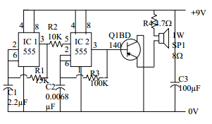
The electronic siren using op-amp 555IC is shown in Fig.This circuit can be used for calling Bell or the emergency etc.

IC1 produce the low-frequency square wave pulses that can be used as the oscillator and IC2 also work for the high-frequency oscillator. The 5th supplied node of IC2 is connected at the end of IC1 output by connecting R2.At low state IC1 output reach 0V and the ground will be simultaneously cut off. In this way, the output signal (high frequency) of IC2 will cause the sound that is simultaneously cut off. The output signal of IC2 will increase by transistor Q2.

By changing the value of R3 and C2 it can be used as the siren of the ambulance and the police cars.
REFERENCES

  1. Electronic Project 1
  1. Electronic Project 2
  1. Devices (Fourth Edition)
  1. Power Electronic

Embedded Project on Missile Detection and Automatic Destroy

AIM:

The main aim the project is to design “Missile Detection and Automatic Destroy”.

COMPONENTS:

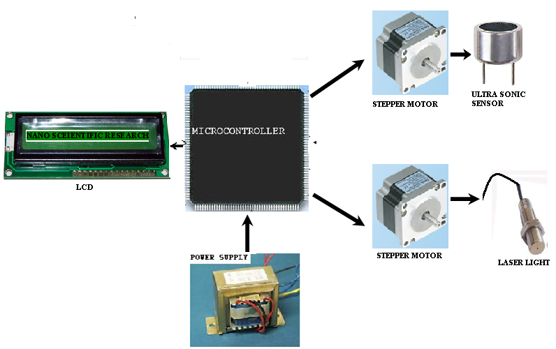
8051, ultrasonic sensor, stepper motor, Laser light, LCD.

EXISTING METHOD:

In the existing method we can detect the missiles and after detecting it informs the control room that some missile is present some location and we need to take certain action after detecting the missile.

PROPOSED METHOD:

In the proposed method we overcome the disadvantage of an existing method. In this, we detect the missile by using ultrasonic sensor after detecting the missile it automatically destroys the missile by emitting the laser beam on the missile.

In this, the sensors are connected to the microcontroller which is used to monitor the at different directions by rotating the stepper motors.

The sensors are connected to the stepper motor so by rotating the stepper motor all directions are the monitor.

Block Diagram:

SOFTWARE: Embedded ‘C’
TOOLS: Keil, Flash magic
TARGET DEVICE: 8051 Microcontroller.
APPLICATIONS: Used for missile detecting.
ADVANTAGES: Detection and destroying of the missile are done automatically.

REFERENCE:

1. The 8051 microcontroller and embedded systems by Mazidi.
2. Datasheets and the user manuals of AT89S52.

Pace Maker Demonstration Unit Project

ABSTRACT

In the body, the heart is the main vital organ, which works continuously without any rest since the baby is in the womb until the death.

There is no rest for the heart and works at a rate of 72 beats per minute on an average, in a healthy person day in day out. In order to make the heart work, there is a specialized tissue located on the heart muscle and is known as Sino-Atrial node or abbreviated as S-A node.

This node generates impulses at regular intervals, and is under the control of autonomic nervous control system, and is popularly known as “natural pacemaker”.

In certain physiological conditions or with certain diseases related heart, the working of S-A node is impaired and in those circumstances the heart does not stop all at once, and provides sufficiently long time for the ultimate failure.

In such cases, there is occasional missing of a heartbeat, initially, and the disease progresses slowly, and the missing heartbeats increases in its frequency, which will lead to other problems, if not attended.

In such cases an artificial pace maker is devised and this instrument identifies the missing heart beat and provides its own pulse at the site stimulating the heart, so that ceased heart beat is continued.

In the proposed project, a micro controller based unit is devised which continuously monitors the ECG waveform, to identify the missing heart beat.

When ever it identifies the missing heart beat it provides the stimulating of sufficient energy, to make the heart function. The proposed project clearly demonstrates the function of the Pacemaker.