Multi Purpose Bridge ECE Project

Aim: The Multi Purpose Bridge designed here can be used for crossing the road; the same bridge constructed with crane mechanism at its bottom side also can be used as crane for lifting & carrying the packages across the road without disturbing the traffic.

WORKING: The Multi Purpose Bridge is constructed with metal sheets & the crane mechanism is designed with two DC motors. The mechanical transition section is aimed to lift the luggage up to certain height & it is carried to the other side of the road.

The crane is controlled through wireless operates, & the wireless network is designed with RF modules operates at 433MHz, so that the operator can sit at one place & can handle the crane.

The control circuit is designed with 89C51, & motors are driven through ‘H’ bridge. The system is quite useful for big cities.

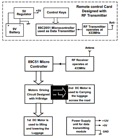
Multy Purpose Bridge Blockdiagram Includes

  • 89C51 MicroController
  • Motors Driving Circuit Designed with H-Bridge
  • 1st DC Motor is used to lifting and lowering the Luggage
  • 2nd DC Motor is used to Carrying the luggage across the road
  • RF Receiver operates at 433MHz
  • Antena
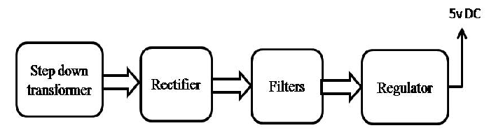
  • Power Supply unit for data transmitting module
  • +12V
  • +5V
  • GND

Remote control Card Designed with RF Transmitter

  • 9V Battery
  • 5V Regulator
  • Control Keys
  • 89C2051 Microcontroller used as Data Transmitter
  • RF Transmitter operates at 433MHz

Automatic Switching Of Induction Motor

Automatic Switching Of Induction Motor Abstract:

INTRODUCTION:  Now-a-days, water crisis in India has been reached to alarm proportions and its wastage during transmission is identified as the major cause responsible for the problem. So in order to resolve the issue to some extent we have come up with Automatic switching of induction motor in houses, this project which is a simple model used to conserve water as well as electricity, and can be implemented in the real time work.

BLOCK DIAGRAM:

 Power supply

Over head Tank

Motor pumps the water into the overhead

Tank when switch gets on by microcontroller.

Water level indicating circuit

Sensor

Motor switch

Micro controller (8051)

Motor

Power supply

Water level indicating circuit

Sump or Reserve  Tank

Power supply

Automatic Switching Of Induction MotorEXISTENCE:

The basic idea for the project is water level indicating circuit. The water level indicator is operated with the help of IC 555 timer. The IC 555 timer is provided with inputs as soon as the level of the water in the sump or reserve tank reaches to a predetermined level. As soon as the water touches the predetermined level, the water level indicating circuit indicates its users by alerting through a beep sound.

PROPOSAL:

The above existed idea of water level indicator circuit is used twice to indicate the levels in the sump as well as the overhead tank and the output of the two water level indicators are given as the input signals to microcontroller. The Microcontroller is programmed in such a way that if water level is above the minimum water level in lower tank, water gets pumped to upper tank and as soon as the upper tank gets filled, motor switches off automatically.

TOOLS REQUIRED:

  1. Two water level indicators Software required:
  2. An overhead and underground tank Keil C Software.
  3. 8051 Microcontroller
  4. Power supply

  FEATURES AND ADVANTAGES:

  1. Constant and reliable water supply.
  2. Functions with minimal or no human interface.
    3. Easy maintenance; install and forget for years.
  3. Low cost and it is absolutely affordable by all.
  4. Prevents dry running of motor and so water, energy, power not get wasted.

APPLICATIONS:

  1. Monitoring and controlling of water level in reservoirs, dams are important in applications related to agriculture, flood prevention etc.
  2. Domestic, industrial, medical fields etc.

CONCLUSION:

The main objective of the project is to automate process of water pumping in a tank, ability to detect the level of water in a tank, switch on/off the pump. Hence from our proposal of “Automatic switching of induction motor,” water wastage gets controlled by constant and reliable water supply.

HealthCare Monitoring Systems For Patients Using Zigbee

In Our project “Outdoor wireless healthcare monitoring systems for patients based on Zigbee”, we implemented a wireless biomedical system based on Zigbee. This paper addresses the medical applications of wireless networks in health monitoring systems. The main objective of our project is to intelligent mobile health care monitoring system based on Zigbee concept.

WHMS Architecture:

The main functions of the integrated WHMS Architecture are automatic monitoring of the medical physiological parameters such as body temperature, pulse rate and heart rate and providing a communication interface between the patient and the monitoring persons. The design and of WHMS Architecture and functionalities are explained in the later sections.

GSM Architecture:

In Healthcare Monitoring Systems paper we discuss about the terms and conditions of implementing the communication GSM interface having Authentication Center (AUC), Equipment Identity Register (EIR), The Base Station System (BSS), GSM transmitter, and GSM Modems and Modules.

Download Healthcare Monitoring Systems Project Report

Automatic wireless health care monitoring system:

The hardware requirements and the software requirements of the proposed system are:

  • Micro controller – a low power high performance PIC16F877A micro controller.
  • Sensors – LM35Temperature sensor, MPX10 Pressure Sensor, LM358 Heart beat sensor.
  • Communication interfaces – Zigbee module, GSM modem, MAX 232.
  • Display and power supply – LCD is used to display the status of the micro controller, and the power supply circuit consists of an assembly of step down transformer, rectifier, filter and a voltage regulator.
  • Software used – MPLAB Integrated Development Environment (IDE) is the software used to implement the programming of the device using HI-Tech PIC C Compiler, the programming for Microchip PIC micro controller is based on the embedded C programming language.

Renewable Sources of Energy Project

In this paper on Renewable sources of energy we demonstrated the need of fuel cells in modern day’s utilization of natural renewable energy resources. In order to the increasing demand of electricity under limits there is an intense need of utilizing renewable energy resources in the production of electricity.

In this paper we discuss about the concept of fuel cells with their applications. a fuel cell is a electrical cell which converts hydrogen or hydrogen containing fuels into electricity by electrochemical reaction of hydrogen and oxygen into water, the bi products of this mechanisms are heat and water. And these are highly applicable in residential applications.

Project Title:

Renewable Sources of Energy Project

Need of fuel cells:

  • These devices can produce electricity randomly in quick time.
  • For continuous supply of electricity over long period of time.
  • Portable electricity generation mechanisms i.e. portable power supply units.

Video presentation for this project

http://www.youtube.com/watch?v=IkcHendv-6o&feature=youtu.be

Abilities:

  • Space applications like providing electrical supply for the space craft.
  • Each fuel cell is capable of supplying 12 kilowatts continuously in shorter periods.
  • In the Shuttle program, the fuel cells are highly reliable.
  • They can provide both electrical power and drinking water.
  • The main source for Low Emission Vehicle Programs.

Download Renewable Sources of Energy Project Report

This project is useful for electronics and electrical communication students as final year project. Download paper presentation ppt from below links.

Laser Guided Door Opener Project Report

Laser Guided Door Opener Project Report explains in detail about how to control the equipment by means of a laser guided pointer i.e. laser beam. When the laser torch emits the laser beam and when this beam gets interrupted the electromagnetic relay gets operated to control the electrical ac/dc equipment with light intervention in the electrical wiring.

These laser guided system can control any electrical appliances using an LED laser diode for laser transmission. Laser guided control systems find applications in several industrial automation principles like Security alarm, Automatic Door Opening System, and automatic Car Parking Systems.

Architectural overview:

The phenomenon of this project is to develop a laser based electronic circuit which can control the electrical appliances using an electromagnetic relay and alarm circuit. And this circuit is developed ion future by using wireless interface technologies in industrial automation.

The components and the block diagram representation are as shown below.

Laser diode:

These laser diodes are also termed as injection laser and diode laser. It is an semi conductor device used for the production of coherent radiation i.e. light rays with same frequency, and these laser diodes find applications in optical fiber systems, remote-control devices and detection systems.

Project Title:

Laser Guided Door Opener Project

Youtube video link to view circuit diagram, block diagram

http://www.youtube.com/watch?v=iiuDpqYrMlo&feature=youtu.be

Sensor:

The pho transistors are used as the light sensors in this project. These are highly sensitive to light.

Controller circuit:

The electromagnetic is intended to operate a switching mechanism mechanically under necessary conditions. The relay coordination with the laser beam is responsible for the device optimum performance.

Download Laser Guided Door Opener Project Report , circuit diagram, paper presentation.

TV Remote Controlled PC and Devices with Password protection

The main aim of this project is to control the computer system using TV remote in a secure way (password enabled). This system also controls the electrical devices connected to the same system. Instead of using mouse, one can use the TV remote from certain distance. This remote can perform all the functions that mouse carries like, Left-click, Right-click and movement of the cursor etc. This facilitates user to open or close any documents, control music system, Google application control etc. User can also use Internet service using on-screen keyboard application which is default with windows.

This system makes use of electromechanical switch called Relay to which the appliance to be controlled is connected. This switch is interfaced to the Microcontroller. The Microcontroller controls this switch according to the input it gets from the IR receiver.

This system consists of an IR receiver that receives the Infrared signals from the TV remote. These signals are fed as input to Microcontroller which processes them and the commands specific to PC operation are sent to the application running inside the computer. The communication between the microcontroller and PC is done by the use of Serial RS232 communication. By using this we can operate any software in computer system like windows media player, browser and etc… To achieve this task, the Microcontroller is programmed with intelligent software written using Embedded C language.

The objectives of the project include: 

  1. Wireless PC control.
  2. Control electrical appliances with TV remote.
  3. Secure way of PC control.
  4. Password enabled control.

This project focuses on the following advancements: 

  1. IR technology.
  2. Mouse control using software.
  3. Conversion of AC supply to DC supply.
  4. Microcontroller and serial port interface.
  5. Embedded C programming.
  6. PCB design.
  7. High voltage devices operation using microcontroller.

The major building blocks of this project are: 

  1. Regulated Power Supply.
  2. IR Receiver.
  3. Micro Controller
  4. Crystal oscillator.
  5. Reset.
  6. MAX 232.
  7. LED Indicators
  8. Electromagnetic Relay with driver. 

Software’s used: 

  1. PIC-C compiler for Embedded C programming.
  2. PIC kit 2 programmer for dumping code into Micro controller.
  3.  Express SCH for Circuit design.
  4. Proteus for hardware simulation.
  5. PC with application 

Regulated Power Supply:

 TV Remote Controlled PC and Devices Regulated Power Supply

Block diagram:


TV Remote Controlled PC and Devices with Block Diagram

Elimination of RHP Zero for the Improvement of Performance of Boost Converter

Introduction to  Elimination of RHP Zero for the Improvement of Performance of Boost Converter Project:

We first revisit the small signal modeling of a CCM boost converter, and confirm the presence of a RHP zero in its control-to-output transfer function. We then explain the operation of a tri-state boost converter. We carry out the formulation of the open-loop small signal model of the same. We discuss the choice of control variables for possible elimination of the RHP zero. Finally, we propose a current control scheme for the tri-state boost converter circuit configuration.

The proposed scheme (a) completely eliminates the RHP zero, (b) Gives a superior dynamic performance in comparison with the schemes proposed earlier, (c) Achieves a step up ratio greater than 3 with stable periodic behavior without the use of a compensation ramp. We discuss the need of feed-forward control in enlarging the operating region, improving dynamic performance and efficiency. We carry out fast scale stability analysis and slow scale transient analysis. We validate the theoretically predicted behavior experimentally. Finally, we briefly discuss about the elimination of the RHP zero in a buck-boost converter. 

A Conventional Boost Converter 

The schematic of a conventional boost converter is shown in Fig. 1. For a dc-dc boost converter, if the MOSFET on-time (related to the duty ratio) is increased, the capacitor discharge time increases which implies a reduction in the output voltage. The output voltage continues to dip further until the inductor gets sufficient energy to build it up again, which results in an initial undershoot of the output voltage.

Future Plan 

  • We improve the performance of boost converter by the improving of this technology by designing the values of parameter k1, k2, k3, kp, & ki. 
  • Use other techniques for tri-state boost converter control like the constant charging interval and dual mode control, recently proposed in the literature. 
  • Implement this topology for Buck- Boost Converter.

Automatic Room Lamp Abstract

Automatic Room Lamp

DESCRIPTION :

First, let us understand why to use Automatic room Lamp? Now-a-days we are going through lots of advertisments of saving electric energy. With the help of Automatic room Lamp we can save and reuse energy. Find the simple block diagram of Automatic room Lamp.

BLOCK DIAGRAM of Lamp

The above block diagram of Automatic room Lamp used to disables the room lamp at day time and enables at night night time. Light Dependant resister(LDR) is the key element of Automatic room Lamp.

Operation:

We need to fix LDR Circuit near to the window/door of home where it can receive maximum sunlight.At day time if we open the door, the resistance of LDR Circuit reduces and leads the transister to remain in cut-off state. So the relay doesnot energize enough,and lamp remains off.
At night time, the resistance of LDR Circuit becomes high and its makes the transistor from cut off state to conducting state. The relay becomes energize and makes lamp to switch on.

We need power supply too operate the following operation.


BLOCK DIAGRAM OF Power Supply

This is block diagram of basic power supply circuit. Transformer is used to step up or step down the input voltage. The bridge circuit is used to convert the alernating current to a pulsating direct current. Since pulsating dc is not desirable, we used filter to convert it to more desirable dc. Regulator is used to maaintain the output of the power supply at a constant level.

Benefits :

Operated only at +5V(d.c)

No use of man power

Used in:

  • Houses
  • Educational Institutions
  • Medical halls
  • Shopping Malls

I2C Protocol Implementation with RTC and EEPROM ECE Mini Project

Project Title:

I2C Protocol Implementation with RTC and EEPROM

Introduction:

I2C is the protocol or serial bus that is used in the EEPROM memory to host the interface devices. They are generally used in the embedded devices that have time clocks and they are based on the real time systems. It can be connected with many devices with just two wires. The master devices used initiated the control to I2C and clock is transferred to slave devices. I2C support the speed of 100 Kbits/s. with the help of we can connect up to 256 slave device to the master with just the same two wires.

Project Requirements:

RTC is used in the portable systems for such as smart card reading and logging data that is used to keep the track of the day and time. This coding can be done in the C languages. To install this code on the device we need to have AVR studio simulator and ISP that will convert the C code in the HEX file. We use EEPROM for the memory.

I2C Protocl Implementation Project Block Diagram:

I2C Protocol Implementation block diagram


EEPROM is the nonvolatile memory that is generally used for storing digital data. Once the data is stored it will be permanent and it doesn’t need any power supply to maintain the record. The data entered can erase electrically and then we can add new data. They are simple and small and they easily get fits in to the small chips.

They are used for making real time clock based systems like DS1307ic. We will need ATmega 8535 microcontroller that will manage the whole work on the system, 20×4 LCD panels that will be the display of the system, EEPROM that will be the memory of the device, interface that will be provided by DS1307 hardware module and at last GUI for writing C code.

GSM Based Home Security System Project B.tech ECE Idea

Project Title:

GSM Based Home Security System Project

Introduction to GSM Based Home Security System Project:

When we talk about the security the one thing come in mind that whether our home is secure or not. It is must to secure our home first then look at other things. Our home has always important documents, money and other precious things, that need to be protected from the intruders or thieves.  We also need to protect the home from fire and gas leak as they can also destroy our home.  We can use security device at our home that will warn us from any harm by alarm or sending SMS to cell. We can use 8051 micro controller or 89s52.

GSM Based Home Security System Project Block Diagram:

GSM Based Home Security System Project B.tech ECE Idea

They are low power chips. They are high performance chips with 8 bit and they is flash memory for storing data.This flash memory allows them reprogram when required. Flash are made up of monolithic chips as they are highly flexible and loss cost. They consist of 32 I/O lines, timers, pointers, oscillators, and clocks etc.

For this microprocessor we use the software called Kiel u- version. This provides tools for the development of the software of the 8051. With the help of this we can generate embedded applications. They use the protocol command named as AT command. They receive the message comes from the phone, then decode the SMS, authenticate the number. Then use their ports to control the specific appliances and after the operation send the feedback to the users for the confirmation.AT command sets are used for the GSM service to connect the device with the mobile phones.

Functions: they have internal RAM and ROM.  Input output ports for programming, timers and counters, 8 bit status words. They contain two 16 bit timers with 4 banks of registers. The RAM used has the memory of 128 bytes. 80 bits are assigned for the general purpose of data memory.