Android Project Sample Code

Computer science final year students can download android project sample code which will be useful as reference for final year students.  In present mobile systems android operating system are widely used because of free apps option. Android has created scope for developing our own apps which can be used as final year projects in colleges.

Here we provide large collection of android sample projects with source code which will help students to gain knowledge. 

MS Dissertation Topic on Airline Reservation System

Introduction to MS Dissertation Topic on Airline Reservation System:

The main aim of this paper is to develop an automated airline reservation system. At present, our system is based on paper work which is manual. There are many disadvantages which arise by this system such as errors and long time is required. To avoid these problems, this software is being developed. By using this software, user can fulfill his desire such as information’s about Flight time schedule and Passenger detail. This software requires Microsoft Visual Basic 6.0,MS Access and operating system.

Brief into Airline Reservation System:

This is a software package that generates the ticket and result is stored automatically. This software includes two platforms i.e., exercise reservation platform and management platform. To access this software unique use rid and password is given. The user can login by giving the appropriate username and password given to them ad can search for the details of flight schedule. In this user can search the flight based on its type , class , to and from station and date.

After searching the flight he can book the details by filling in all the details given in the passenger information form. All the data is stored automatically with a single click. Even the flight maintenance, cancellations can be done. This software is tested and provided an error free environment to the user . It adopts several safety technologies.

Advantages:

This helps to avoid errors caused due to errors and by using this we can improve accuracy. It gives fast responses when compared to responses given by manual system. It is highly secured system.

Download MS Dissertation Topic on Airline Reservation System .

Visual Basic Projects Report on Time Table Generation

Introduction to Time Table Generation:

This project targets to develop software for college in order to handle the ’ Time Table Formation’ for the pupil as well as staff. The head of every Department has problem in delegating work to their subordinates and response for the work position. This software resolves the problem by permitting the pupil and other employees to see their assigned subject and Time-table.

This software helps to handle the particulars of the Time-table of pupil and staff. Visual Basic. NET is employed as front end which is used to craft the user interface. Microsoft Access  is employed as back end and used to craft the database and save the particulars. Anybody with a little computer knowledge can approach and deal with the software with ease, hence it can be termed user-friendly. It also offers security to the users by offering perfect login.

The modules of this project include

  • Course description
  • Department description
  • Employee description
  • Time Table assignment description
  • Subject description

The shortcomings of the existing system:

  • The handling of the augmented source document due to augmented transaction makes the maintenance tough.
  • Maintenance also suffers in case of a wrong pupil or employee entry. 

 The benefits of the suggested system:

  • Offers precise information
  • Eases the manual work
  • It lessens the functions related to  documentation
  • Offers current information
  • Amicable environment by sending caution  messages

Hardware Requirements:

The system should have a Pentium IV processor, a RAM of 1 GB, a 15” color Monitor, a Hard Disk of 80 GB, an LG 52x CD Drive, a Logitech keyboard and mouse.

Software Requirements:

A microsoft Windows XP platform, a Front end-VB.Net, a Back end-MS Access and Environment – Microsoft Visual Studio.Net2005 are required.

Download Visual Basic Projects Report on Time Table Generation .

MS Dissertation Project Screen Shots for Distributed Networks Project

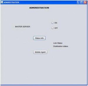
The project begins with the administration module and as discussed in the previous chapter, administrator are provided with an window and from there they can perform the required operations and the actual window created using the coding is as shown below

From the above screen it can be observed that the administrator is provided with an option to start the master server from where the actual operations begin. Administrators are also provided an option check the status of the network and with respect to this link status and distribution network status can be checked in this module and also the administrator can start the mobile agent by clicking on the mobile agent button as shown in the above screen. 

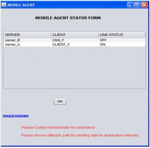
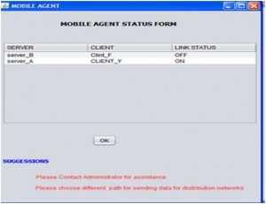
From the above screen it can be observed that the mobile agent module provides the required information related to the link failures and the corresponding information is displayed to the users in the form a table and the corresponding suggestions with respect to these failures are also shown. This module is actually invoked when there are faults across the network and the corresponding faults and network operations are shown below 

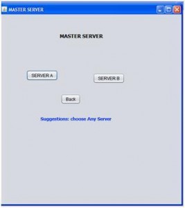
When the administrator click on the start master server this particular window is displayed and it can be observed that users are provided with the option to start the Server A and Server B. When the user clicks on the Server A, server A is started and the same with the case with server B and the next steps are as given below 

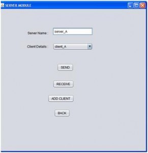
When the user clicks on the server A button, the screen shown above is displayed to the user and from here the actual server operations are initiated. It can be observed from the above screen that users can select the desired client from the list of clients and proceed with the required operations. The users are provided with the options like Send, Receive and Add client and they can click on the desired button to proceed with the required option and the corresponding screens are as given below 

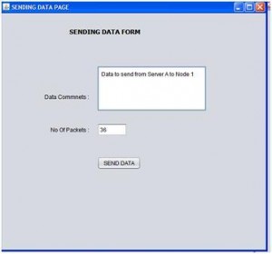
From the above screen it is clear that the users can send the data from the desired server to the desired client and the actual number of packets being sent is also calculated before sending the actual data to the desired client or server. The data sent is saved in the datapackets table as described in the previous chapter. 

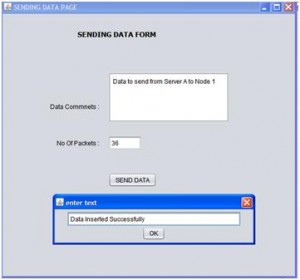
Once the data is sent to the desired client or server, users are shown a message with respect to the data insertion and thus one can conclude that the data is sent to the desired client or server successfully.

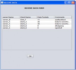
All the data received is displayed in the form a table and is as shown in the above screen. This table contains the key columns like server name, client name, number of data packets sent and the actual message sent. This table can be used to track the log of received data by the administrator and also check the level of communication between the clients and the corresponding servers. 

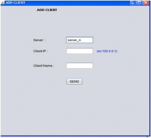
This screen shows the procedure to add a client to a particular server and if the users selects the server A to add the client, then the server A is populated by default on the server field and the users can add the client IP address and the client name. This client is added to the particular server if the server has the limit to handle the required number of clients.

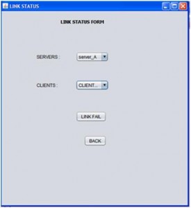
This screen shows the link status form and the users can select the desired server and the corresponding client to fail the link externally. This can be considered as the required fault across the distributed systems and if the server and the client are required and once the link fail button is clicked, then the corresponding link is failed and the communication among these nodes is not possible further and the users should contact the administrator and select an alternative path for the communication as shown in the mobile agent window. 

This screen shows the mobile agent screen where it displays all the nodes that were failed and  now the administrator can select the desired client and server and set back the status as either on or off as shown in the above screen. If any link between the server and client is off, users are provided with an option to contact the administrator for assistance and also they are suggested to choose an alternative path for the communication as shown in the above screen.

This paper is written and submitted by sai

Mobile Agent Based Fault Tolerance System Implementation Procedure in Java

The actual procedure followed to implement the proposed design as mentioned in the previous chapter is explained in this chapter. As mentioned the proposed design is implemented using Java and the all the required screens are designed using the Java swings and the data base is created in Oracle SQL. This chapter summarizes all the important classes and tables used along with the flow of the application are clearly described in this chapter.

Classes used in the application

Every aspect across java programming is an object and these objects can be inherited in the form of class and the objects of the class can be created to initiate the core functionality used across the class. Following are the classes created in this project with respect to initiate the flow of the application. All the classes used across this application are created using the Java swings framework and the flow of the business logic is as listed below

  • AddClient.java
  • Administration.java
  • CommonUtil.java
  • First.java
  • LinkStatusForm.java
  • MasterServer.java
  • MobileAgent.java
  • ReceiveData.java
  • SecondFrame.java
  • SendDataForm.java
  • ServerModule.java
  • UKprogg.java

All the java files are created with an extension of .java and the corresponding logic used across these java files are as given below 

AddClient.java 

Required logic to add the clients to the servers is given in this class. As per the design few clients can be added to the server and the corresponding procedure is coded in this class. Java swing frame work is used to create this logic and all the basic components of the swing class like text fields, layouts and gaps are used to create the basic layout out the of the screen and is as shown in the appendix section. A separate client id is issued to the newly added client and assigned to the desired server and the corresponding logic used here is that the server id is tracked against adding the required client and the newly added client is to the serve and the server is identified with the server id. Once the client is added, a new row is added to the client table and the corresponding query used here is Initially the number of clients are calculated and if this count is as per the defined handled clients for the server, then only the client is added to the desired server else the client is added to the next available server.  Once the required constraints are satisfied the client is added to the client table and the rows are incremented by 1 against the table.  Whenever the client is added to the server and the database is updated, the link status of the server and the client is also updated and set to on the corresponding logic is written.

When the client is added to the server, the corresponding client IP address and the client name are also updated against the database table client. 

Administration.java 

Administration.java class is used to create the user interface for all the administration activities and the coding procedure followed is explained in this section. The key administration tasks used in this project are to start or stop the master server, check the status of the links, start the distribution mode of the network and initiate the mobile agent for detecting the faults across the distributed networks. Administrator can check the status of the links between the clients and the server at any point of time and they are provided an option with respect to this.  A link status form is opened at the user interface and the administrators can view the status of the desired links at this window and even this window is created using the swings. Distributed network option is also available to the administrator and they can initiate the distributed mode of the network.  Admin is provided with an Mobile agent button and the users can click on the button to start the mobile agent, where this agent collects the information related to the distributed network faults and suggests the options for the fault recovery options. The key java code used to create this logic is as given below 
A new object is created in the private methods to initiate the administrator requests and thus the overall functionality of the admin module is coded in this java class.

CommonUtil.java

This class is used to created the frequently used java functions like the database functions and thus if at all a new instance of the database is required an object is created for this class and initiated to dump the complete coding logic in this case.  Following are the important methods used in this class and the corresponding description of the methods are also given below

getConnection

This method is used create the connection to the database and the basic JDBC drivers are used to create the connection to the database using the Connection class across java. Once the connection is established, the corresponding statements and other parameters are initiated. Oracle thin driver is used to create the bridge to the database in this class and the user name and password to access the database are also provided in this method

getServerNameByServerId 

This method can be used to get the server name by providing the server if as the required parameter.  A separate global server is used as the required table and the server information is recorded in this table and thus the information is fetched from the database and the corresponding query used for this process is as given below 
getServerIdByServerName 

This method can be used get the server  name by providing the server name as the required parameter and the value is fetched from the global server database table. Following is the query used to get the required information from the table 

getClientIdByClient_name 

This method can be used to fetch the required client id with the help of client name and the client name is provided as the required parameter to the method.  Below is the query is used to get the required client information with the help of client name 

getClientNameByClientId 

This method can be used to get the client name by providing the client id as the required parameter and this name is fetched from the database table known as client and the actual query is used in this context is as given below 

LinkStatusForm.java 

As mentioned the administrator can check the status of the links from the desired server and the client and the corresponding code is given in this java class. User interface is provided in such a way that the users can select the desired from the dropdown list and also can select the client id from the list and the swing components are used to create this interface.  All the ids of servers and clients are fetched from the corresponding database tables and the required logic is given in this class. Once the users selects these values, these values are given as the input to the query built and this query is fired on the status table to get the current status of the desired server and client and the corresponding coding logic used is as shown below 

Thus the current status of the client and the server can be fetched using this logic and the query as shown above. 

MasterServer.java 

Master server is initiated across this project and the corresponding logic used is given in this java class. From the master server user can start the desired server and in this project two servers are created and named as Server A and Server B and once the user clicks on the desired button, the actual server operations are started. Java swings are used as the required framework and all the key components are added to get the required interface to the application. The actual action performed by user is captured using the action events provided with the swings package and based on the action performed the corresponding server is started and the key coding logic used in this context is as shown below 

From the above code it is clear that if server A is selected the corresponding ID is tracked and the actual server module is started and this procedure is repeated for both the servers as shown in the above code. 

MobileAgent.java 

This is the important class used among all the classes created in this application. Mobile agent is the java class that captures all the link failure information and displays to the administrator and the administrator can set the status to On again using this class and the corresponding functionality used. User is also provided the required suggestion to check the alternative paths across this process and the corresponding functionality is provided in this class. The link status information is fetched from the database and the corresponding logic is used as given below 

 From the above code it is clear that the required information is gathered from the database table link_status and the status values are iterated in a loop using the result set object available with the JDBC package and the fetched values are displayed to the users in a tabular form and required rows are added to this table using this information fetched from the database table.  A vector object is used to store all the values retrieved from the database and the loop is iterated against this loop. 

ReceiveData.java 

As mentioned in the design of this project, clients and servers can receive the data from the any other servers and clients and the required programming logic is given in this java class. All the data received from any other client or server is displayed to the users in the form a table and the required logic is written using the java swings framework and the corresponding components in the swing framework. Database connections are established to gain the access to the information related to all the received data by a particular client or server. A table with name datapackets is created in the database and that particular information is gained from this table and displayed to the users in a tabular form. All the data received is fetched from the table and stored in a vector object and thus a loop is iterated using the JDBC result set object and the corresponding values are displayed to the user and the corresponding screenshot is as shown in the next chapter. The actual coding logic used for this java class is as shown below 

SendDataPage.java 

As mentioned in the design chapter, any client or server can send to the desired client and server and the required programming logic is created in this java file. A window is created across this section and the users can type the desired message to be sent and actual number of packets is also calculated using this logic. A separate text field is created in this class and the client or server can add the required message to the text area and the data entered is sent to the desired client or server and the number of packets sent is also calculated in this class and the corresponding coding done is as given below 

From the above code given it is clear that all the data sent is saved in the database table datapackets  and the inserted text is converted to the desired format and the corresponding client and server information are added as well. A prepared statement is created and the query is inserted to the prepared statement and executed to insert these values in to the database table. 

Following are the database tables used in this application

  • Globalserver
  • Client
  • Link status
  • Data packets 

All the important classes are explained in this chapter and the corresponding code is also provided. The actual results achieved against this implementation are given in the next chapter. 

Results and Snap Shots of Mobile Shopping cart Management System

Results and Snap Shots

  • Loading status user interface design
    • Then the status of the loading will be displayed to the user.

Loading status user interface designWelcome Screen User Interface Design

    • This Welcome Screen User Interface is the part of the Home module.

 Welcome Screen User Interface Design

  • Mobile shop User Interface Design
    • This is the main window of the Mobile Payment Service system through this the user can Login or Register.
  Mobishop User Interface Design

  • Registration User Interface Design
    • This Registration user interface is the part of the Home module. Here the user has to enter the details of username, password, confirm Password, Address, Phone, Email-Id to before login.

 Registration User Interface Design

  • Registration Successfully User Interface Design
    • This Registration Successfully user interface is the part of the Home module. After the user has to enter the details of username, password, confirm Password, Address, Phone, Email-Id to press OK button to registration successfully.

 Registration Successfully User Interface Design

  • Login User Interface Design
    • This login user interface is the part of the Home module. Here the user has to enter the user name and password to perform various transaction of the shop.


  • Invalid Login User Interface Design
    • This Invalid login user interface is the part of the Home module. If unauthorized users access the system, it will be display the error message.

 Invalid Login User Interface Design

  • Offer User Interface Design
    • This offer user interface is the part of the Place order module which displays various offers of the shop. Then the user has various option.

 Offer User Interface Design

  • Help User Interface Design
    • This Help user interface is the part of the Place order module which provide help facility for the user to clarify their doubts and the system to be more interactive.

 Help User Interface Design

  • Search Shop User Interface Design
    • This Search Shop user interface is the part of the Place order module which provides SearchID facility for the user to displays the particular shop. Then the user has various options.
    • Search Shop User Interface Design
  • Department Selection User Interface Design
    • This Department Selection user interface is the part of the Place order module. The user has to select the department of the shop to perform the place order transaction.

 Department Selection User Interface Design

  • Product Details User Interface Design
    • If the user selects the product, the system will provide the product details such as price for the corresponding product, company model and availability.

 Product Details User Interface Design

  • Confirmation User Interface Design
    • In case of confirmation the user has to press the Back button, otherwise press the OK button to continue the process.

 Confirmation User Interface Design

  • User details User Interface Design
    • The user has to provide various details like Name, Address, Mobile Number, and Credit Card Number to place / cancel order.
 User details User Interface Design

  • Verification User Interface Design
    • In case of Verification the user has to press the Enter button, otherwise press the OK button to continue the process.

 Verification User Interface Design


    • The user can specify the quantity.


  • Process User Interface Design

 Quantity User Interface Design

  • Then the status of the process will be display to the user.
 

  • Billing User Interface Design
    • Then the Billing will be displayed to the user using the Name, Address, Mobile Number, Quantity and Rate.
 

  • Display Confirmation User Interface Design
    • Then the Display Confirmation will be displayed to the user using the cancellation and Continue.

 Display Confirmation User Interface Design


  • Cancel order User Interface Design
    • This cancellation user interface is designed, in case if the user wants to cancel the order. The user has specified his Name and Credit Card Number. Then the Name and Credit Card Number will be verified by the system and the process status will be displayed to the user.

 Cancel order User Interface Design

  • Display Cancel Confirmation User Interface Design
    • Then cancel confirmation will be displayed to the user by verifying the username and Credit Card Number.

 Display Cancel Confirmation User Interface Design

  • Display Successfully User Interface Design
    • Then the displayed to the user has to purchase the product successfully. Finally the money is deduced from your Credit Card Number.
Display Successfully User Interface Design

Shopping Cart Project in Java with Module Description

Detailed Description of the Shopping Cart Project

The following are the major components, Home, Place order / Cancel order, User details, Shopping cart, and Display confirmation.

 Home:          

This module providing the information about the shop. It gives following details:

  1. Welcome screen
  2. Offers
  3. 3.     Login

Place order/ Cancel:

              This module prompts the user to enter in to place order / cancellation of shop or else exit from the environment through mobile devices.

User Details:     

              This module prompts the user to give his various information for the product selection through mobile devices. It requires the following:

               1. Name

               2. Address

               3. Mobile Number

               4. Credit Card Number

Shopping Cart:

              This module provides the information about various categories of products and displays their corresponding price. It also includes the various fields like Quantity of a product. 

Display Confirmation: 

               This module gives the confirmation about the product selection / Cancellation.

Place Order: 

             This process is an easy process to order a product. When specifying the product, the display provides the information about the price for that

Corresponding product. Finally the money is deduced from your credit card.

Cancel Order:

             This process is an easy process to cancel a product. Finally the money is backed up to your credit card. 

Hospital Management System Project In VB

This projects deals with Hospital Management. A hospital management tool depends on doctors, Patients and employees. Doctors who are in and off should be checking he statues of this tool and also patients who are joined and who are discharged and taking the appointments in fixed time period. This tool shows what the facilities in hospital are. This tool is involved in the lot of interfaces those are welcome, login, MDI, Doctor, Services, Employee and Ward

The Welcome is involved what time are getting for administration then login is interact with who are authorised person to involved the tool. Using the MDI is to interact with more documents and taking the action of the management then the application is taking the important information for operation services. The Doctor interface is involved is which doctor is available and which doctor not. It is display all the personal information of doctors like address, phone numbers, specialization and qualification.

Searching the doctor information using Id. Add and remove the employee statues using the employee interface also check which department he/she belong to. Outpatient interface is taking care of the patient is paying the bill or not and check with any doctor appointments. Service is taking of which administrator is taking the file and which department is belong the patients and who is in charging the patient. Tool is totally user friendly that will easy to maintain the administrators.

Capabilities are easily maintained database for Employees, doctors and administrators. The database can be access any times management needs and more reliability and more secitry. Tool is a good quality and developed in VB, this is containing various sub tools are developed in checking the conditions and proving the good quality. If the data loss then it should be effected to all the tools and the tool is not totally set in the VB may be upcoming technology is used to developed very easily.

Download Hospital Management System Project In VB.

Mobile Payment Service System Java J2EE and J2ME Final Year Project

At the starting point of this Mobile Payment Service System project I would like to state that the work done in this Java based project is only a small percentage of what can actually done. The existing Final Year Project system involves a huge amount of the time wastage which has been reduced from this effort. This J2EE and J2ME project includes the reuse of the coding which means that the user can use the coding in any where which is needed. Now we are living in a world of reduced computing where the customers are mostly interested in products, which are compatible and user friendly. So we go for a systemized one and therefore it leads to the idea of designing a system, which is fully of user friendly and therefore reducing the strains of user.

Future Enhancements of Mobile Payment Service System

                 We can enhance this Java Student project through GPRS connection. When one shop in more number of departments. If new changes come, it should flexible to new user. At future, we can provide service to product sales by our concern. Our computer science and engineering project, In future it can be enhanced to provide to more effective feature to provide complete management feature. As environments are becoming more mobile, are not just dealing with Distributed Processes any-more, Process Landscaping methodology is developed. Finally, the use of Hypertext-Based User Interface (UIs) mobile application, the simple information elements and interaction techniques of hyper-based UIs can be rendered on various presentation channels, ranging from desktop to mobile.

Advantages and Applications of the Project:

  • All the business activities are mobilized.
  • It provides security to the data.
  • It also provides data hiding.
  • Almost all action is provided by GUI interface that will provide the easy to use environment for the user.
  • The access to the Server information is more secured by using
  • the Authentication process of manager.
  • This will greatly reduced the cost by saving the cost and time.

UML Diagrams of Java and Oracle Mobile Management System

UML Diagrams of Mobile Management System

The unified modeling language is a language for specification, constructing, visualizing and documenting the software and its components.

The UML is a graphical language with set of rules and syntaxes. The goal of UML is to keep the modeling simple.

ACTIVITY DIAGRAM

            Activity diagram is used to model an entire business process. The purpose of the E-R Diagram and activity diagram is below.


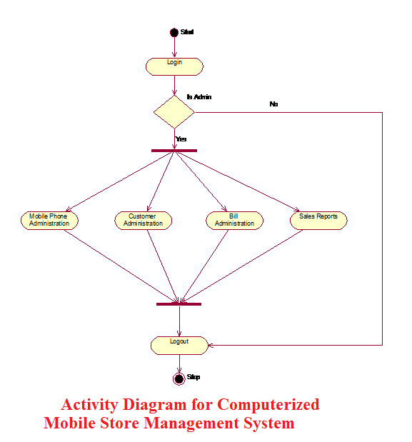
Activity Diagram for Computerized Mobile Store Management System

Activity Diagram for Computerized Mobile Store Management System                                                                                             

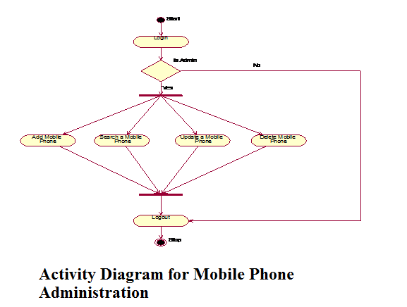
 Activity Diagram for Mobile Phone Administration

Activity Diagram for Mobile Phone Administration

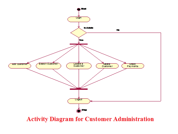
 Activity Diagram for Customer Administration

Activity Diagram for Customer Administration

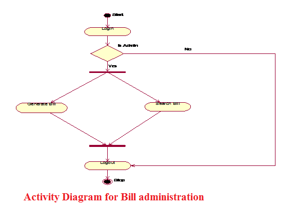
 Activity Diagram for Bill administration

Activity Diagram for Bill administration

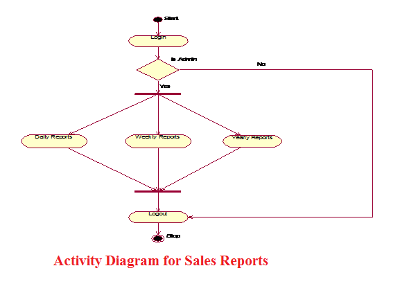
 Activity Diagram for Sales Reports

Activity Diagram for Sales Reports

USE CASE DIAGRAM


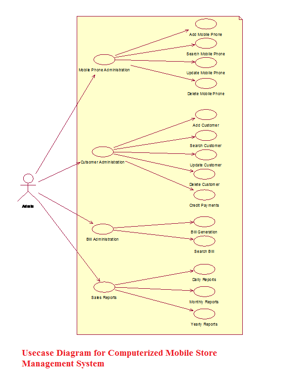
Usecase Diagram for Computerized Mobile Store Management System

 Usecase Diagram for Computerized Mobile Store Management System.

Use Case Descriptions

  • Mobile Phone Administration:

In the “Mobile Phone Administration” the Administrator adds, updates, searches, and deletes the Mobile Phones details on his system.

Add a new Mobile Phone:

Here the administrator adds the new Mobile Phones into his system. Here administrator enters the Mobile details like MobileId, MobileModel, Mobile Price, Mobile Phone Color, etc.

Search for a Mobile Phone:

Here the administrator searches a Mobile Phone details by entering the input like Mobileid, Mobile Phone, and Price.

Update a Mobile Phone Details:

Here the Administrator Updates the Mobile Phone details by modifying the Mobile Phone details.

Delete a Mobile Phone:

            Here the Administrator Deletes a Phone details by entering the details like MobileId or IMEI no.

  • Customer Administration:

In the “Customer Administration” the administrator adds, updates, searches, and deletes the customer details on his system.

                   Add a new Customer:

Here the administrator adds the new Customer details into his system. Here administrator enters the Customer Name, Customer Address, Mobile purchased, MobileId etc.

Search for a Customer:

            In the ‘Search for a Phone’ system the administrator searches a Customer details by entering the input like CustomerId, Customer Name.

Update a Customer Details:

            In the ‘Update a Customer Details’ system the administrator Updates the details by modifying the details like Customer Address, Customer credit details.

Delete a Customer:

            In the ‘Delete a Customer’ system the administrator Deletes a Customer Details by entering input like CustomerId. 

  • Bill Administration:

In the “Bill Administration” the administrator generates and searches the bills.

Generate a Bill:

Here the Administrator generates the bill for sold Mobiles. Here he enters the information like Customer Name, Customer Address, Mobile Purchased, MobileId.

Search for a Bill:

Here the Administrator searches the bills by entering the details like Billid. 

  • Sales Reports:

                        In the “Sales Reports” the administrator can generate the Sales Reports for daily, monthly and yearly.

                        Daily Reports:

                        Here the Administrator can generate the Daily Sales Reports by giving the  input information like Date on which the Sales Reports are needed.

                        Monthly Reports:

                        Here the Administrator can generate the Monthly Sales Reports by giving  the input information like Month and Year on which the Sales Reports are                             needed.

                        Yearly Reports:

                        Here the Administrator can generate the Yearly Sales Reports by giving the input information like Year on which the Sales Reports are needed. 

SEQUENCE DIAGRAM

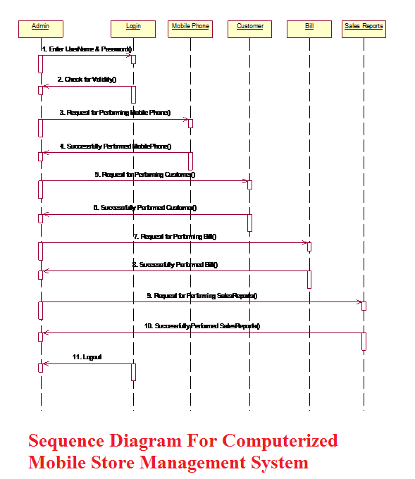
Sequence Diagram For Computerized Mobile Store Management System

Sequence Diagram For Computerized Mobile Store Management System 

CLASS DIAGRAMS

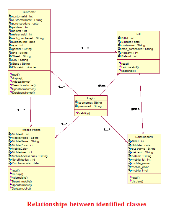
Relationships between identified classes

Relationships between identified classes.