Profile Definitions in Default Wireless LAN Configurations

Profile definitions

On the whole OPNET every application developed to produce the traffic around the entire network should be backed by a profile description and this is developed by utilizing the profile configuration node as seen before. Every application has an independent profile and we create three applications in this situation three profiles need to be maintaining.FTP, Voice, video profiles are created and in all the scenarios the beginning time and end time are fixed in this level.

In this scenario the beginning time is fixed as ideal value as 10 seconds which is default and the process is again started once it comes to the end time of that particular profile. Once the desired profiles are created now the necessary mobility to the nodes should be appended it is clearly explained in the next section below:

Mobile Definitions in Default Wireless LAN Configurations

Mobile definitions:

In this particular simulation, mobile nodes are selected from the object palette and therefore all these nodes must be added with mobility as a necessary requirement. The mobility model selected in the scenario must be supported by all the 10 mobile nodes selected for simulation and a mobile configuration node is selected for defining the mobility model.

By opening the object palette the mobile configuration node is dragged from it and placed on the work station to establish the mobility model and a random waypoint model which is default is implemented as the mobility model and the selection of this model is done at the “mobile configuration node level”. In addition to the selection of mobility model there few other factors that are required for the simulation and they are mobility speed which is set 100 meters per second and the pause time which is set to 0 seconds.

That means that the movement of the mobile nodes across the network is maintained at a speed of 100 meters per second and the time the nodes get paused will be 0. All the 10 mobile nodes should be added with this mobility which is defined and this can be achieved by using the topology menu. The next chapter explains the detailed process of this mobility configuration.

DSR Protocol Simulation

Simulation for DSR is similar to DES protocol but the routing protocol set for the mobile nodes and the server is alone changed. The steps to be followed in this protocol are as follows:

  • Choose all the mobile nodes and the server from the simulation environment
  • Select any one of the mobile node and edit it to the attributes level.

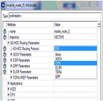
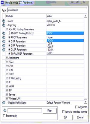
Go to the ad hoc routing protocols menu and change the routing protocol to DSR. Remember it was AODV with DES protocol. Refer the corresponding screenshot given 

From above screen it can be observed the AODV routing protocol is changed to DSR routing protocol.

Simulation of third scenario: TORA

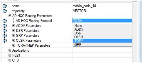
It is same as the second scenario only the routing protocol is changed to TORA throughout the process. Watch the screenshot below carefully.

This completes the simulation of all three protocols and the next step is to run the simulations against its simulation time. All the three scenarios are run for 15 minutes to achieve the results. 

Ad Hoc Network Project Reference for Setting Up The DES Metrics For Performance Evaluation

The main aim of this process is to analyse the packet losses in the network. The following steps are to be followed in setting up the DES metrics.

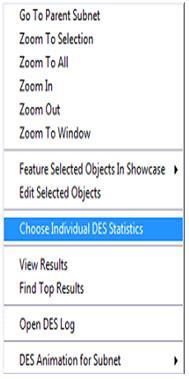
  • Right click on the simulation environment and chose the option  and Choose ‘Individual DES statistics’
  • A new window is opened where three options like global, link and node level are available. You got to choose the right option to evaluate the performance of the network
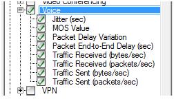
  • Refer  the following screenshot for Global level attributes, if chosen .

The following are the actual performance metrics used across the network against the traffic and packet sequences.

  • Jitter time in seconds
  • MOS Value
  • Packet Delay variation
  • Packet end to end delay in seconds
  • Traffic received in bytes per sec
  • Traffic received in packets per sec
  • Traffic sent in bytes per sec
  • Traffic sent in packets per sec

The same process stands good and can be applied for the second and the third scenario as well. The following are the actual simulation methodology implemented for the other scenarios. 

Node Level Configuration at Default Wireless LAN Configurations

Node level configuration:

Using the simple drag and drop approach provided by the OPNET modeler all the nodes required for the simulation are selected from the object palette and placed in the work station. All the types of nodes dragged are needed to make some changes and this process is generally called as configuration of nodes and this section concentrates on the explanation of the configuration process. Firstly the 10 mobile nodes taken from the object palate are also need to make some changes and in order to make the changes right click should be given on the node and can then select the edit option.

All the nodes must be allocated with a routing protocol in order to establish the routing process needed for the network, several routing protocols are supported by MANETs and some among them are OLSR, AODV, DSR and TORA, these are also supported by the simulation selected in this simulation. OLSR routing protocol is selected for the simulation this particular scenario and therefore all the 10 nodes taken here must be allocated with the OLSR routing protocol.

This routing protocol is also allocated to the wireless LAN server to support the simulation. The other nodes such as the application, profile and mobile nodes also require some changes and are configured by editing the attributes and parameters. The next chapter that is the simulation procedure chapter gives a clear idea of how these configurations are made.

Improving the security level in wireless LAN network is the significant aim of this project and so the configuration of the scenario is done based on this requirement. The settings needed for the configuration of next scenario is done in next level.All the settings done to the nodes will support the simulation process as the default attributes of wireless LAN are made automatically using the OLSR routing protocol. The sections below explain the other configuration like application, profile and mobile nodes.

Setting the Mobile Definitions to the Nodes Ad hoc Project Reference

The main constraint of a mobile launch program is the packet losses across the network. This could be kept at a minimum by keeping the nodes used in the simulation pre set against few mobility patterns and these nodes can be added using the mobile configuration program. This mobility pattern is very important as if defines the destination, source and speed of the mobile nodes and the functioning of the mobile network on the whole.

The following points should be considered to set the mobility of the mobile nodes.

  • Right click on the object to edit mobile configuration object
  • Choose random mobility profile from the various options that prop out.
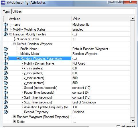
  • Expand the option, default random waypoint tab and set this as the required mobility model to the nodes. Check the corresponding screenshot given below for your reference.

From the above said process, random waypoint parameters are set and from the above screen it is clear that the speed of the mobile nodes is set to a constant value of 10, pause time is set to a constant value of 0 seconds and start time of the mobile nodes is repeated for every 10 seconds. Stop time of the simulation is set to bring about an end to the simulation as shown in the above screen.

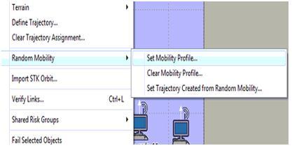
The edited mobility profile should be applied to all the mobile nodes and this can be achieved by choosing the option, ‘set mobility’ from the topology menu. Refer to the pictorial representation below to clear any of your doubts.

Once the mobility profile is set as shown above, all the mobile nodes should be assigned with this random waypoint mobility which helps the nodes to move randomly to process the traffic and to deliver the corresponding packets to the destination side. With this step the process of setting up the mobility patterns to the network nodes is done and the next step is to define the performance DES metrics. Its process is as follows. 

Default and Secured Wireless LAN Configurations

Introduction Design of Simulation

                       This chapter deals with the explanation of the design that is actually followed in this simulation project. Improving the level of security in wireless LAN networks is taken as the significant aim of the simulation project and to achieve this aim two scenarios are considered. The design that is implemented in simulating these two scenarios is explained in this chapter. The default wireless LAN configuration is used for the creation of the first scenario and secured wireless LAN configurations are used for the creating the second scenario. The further sections of this chapter explain the design of creating the networks:

Design of default wireless LAN configuration scenario:

The simulation procedure of this application is done by creating two scenarios as indicated earlier and the creation of first scenario and the design principles that are implemented in creating and simulation of the scenario are explained in the present section. The main aim of the project is to improve the security levels in wireless LAN, For achieving this aim a Mobile adhoc network is selected as the as the wireless sensor network. The default networking conditions of the first scenario is with the common configuration of the wireless LAN.

The sensor nodes required for the simulation of this particular scenario are considered using 10 mobile nodes and one fixed wireless LAN server is selected to behave as the sink node to handle all the mobile nodes. Then the network required is created in this approach as there is no other specific approach for the creation of wireless sensor network using OPNET modeler. The design implemented for configuring the required network setup is explained in the following sections.The entire design of the scenario is classified in to various factors and they are clearly explained in following sections:

Basic Network Setup

Node Level Configuration

Application definitions

Profile definitions

Mobile definitions

Setting the Performance Metrics

Design of secured wireless LAN configuration scenario:

As discussed initially the second scenario is created to propose the secure wireless LAN configuration and this scenario is the copy of the first scenario and there are few changes done to the wireless LAN configuration and they are as given below 

  • Transmit power is set to 0.020
  • Packet reception power threshold is set to -76
  • RTS threshold is set to 256
  • Fragmentation threshold is set to 256
  • CTS to self option is set to enabled
  • Short retry limit is set to 11
  • Long retry limit is set to 9
  • AP Becon interval is set to 0.02 seconds
  • Max receive life time is set to 1.2
  • Buffer size is set to 64000
  • Roaming capability is set to enabled
  • Large packet processing is set to fragment

Once all these steps are followed the simulation design is completed and the simulation steps followed are explained in the next chapter. 

Simulation tool: OPNET modeler and its importance

Simulation tool:

As discussed in the introduction section of this chapter the simulation procedure of this application considers two scenarios and the simulation tool used for simulating the scenarios is OPNET modeler. In comparison with different simulations tools like OMINET and NS2, OPNET modeler is considered as the best simulation tool as it provides several advantages that they cannot provide.

The significant advantages of OPNET modeler are it supports level of models and provides a user interface to establish several networks. Not only OPNET modeler, NS2 is also considered as a best simulation tool but the single disadvantage in using NS2 is its behavior which is very complex as it includes loads of coding part and this problem is completely avoided using the OPNET modeler.

The significant factor that encourages the usage of OPNET modeler is its drag drop approach, using this approach the simulation procedure is done very simply by selecting the required objects from the object palette that is available by using the OPNET and the configuration of the objects is also provided, the other important feature of OPNET is it supports several model families over the wireless network to enable the communication.

The network setup required for the simulation can be completed by dragging the required objects from the object palette and then by configuring them according to user’s requirement. The model of the simulation includes the operations like establishing the network needed, checking the consistency of the model, simulation running and at last estimating the results.

Irrespective to the type of network to be created these steps are followed in creating the wireless and wired networks. Because of this reason OPNET is regarded as the simple way out to create any network. In addition to the above models of networks, latest network technologies are also provided by OPNET such as the Mobile Adhoc networks, Zigbee networks and wireless mesh networks. Using these available models the estimation of network’s performance can be done easily. 

Node and Server Level Settings for Packet Analysis CSE Reference Material

In order to define the traffic as well as the packet analysis the node as well as the service level settings are needed which are against the nodes and then the overall configuration is been followed further in order to explain the server and node level settings. As discussed earlier, there are 20 different types of mobile nodes along with the single wireless LAN server and then the nodes which are been configured towards the traffic analysis as well as the packet analysis is situated in the initial step. The steps required to perform this activity are explained below:

  • Select the appropriate mobile nodes as well as the WLAN server
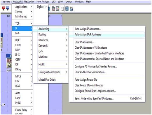
  • Then after go towards the menu called protocol -à ApplicationsàIP
  • Then after starting from the IP section select the option called Auto assign and then the IPV4 address through which the actual nodes as well as the WLAN server which are allotted are been sent to the alternate !PV4 address and the screen shot which explains this process is shown below:
server 1

The auto assign IPV4 address which are been selected for the entire process are been allotted to the different mobile node along with the wireless LAN server as explained in the below screenshot. The next step is to configure the mobile nodes as well as the server which is added towards the routing protocols. It is explained in the earlier section that AODV is been used for the purpose of desired routing protocol the applicable mobile nodes along with the WLAN server is used and the steps are explained below:

  • The routing option is available to node levels or else to the server levels which are used to select the entire mobile nodes as well as wireless LAN server.
  • Within the entire available nodes, a single node is selected as well as opened within the edit mode which can be performed by clicking on right button
  • Within this edit mode the quality such as Adhoc routing protocols are used which allows the server to display the entire list of the routing protocols towards the users starting from AODV scenario and the process will be explained in the below screen

AODV is been chosen from the available list in which the total number of routing protocols which are seen in the screen can select al the nodes along with the server that are against the AODV protocol and it can be verified in the form of selected objects shown in the screen displayed above. In the entire process if the routing protocol is all set to serve the traffic against the patters of routing parameters the nodes as well as the server will be totally against the applications and profile definitions process is explained below. The total application level settings are situated towards the nodes that are explained below:

  • The total number of mobile nodes are been selected starting from the simulation networks and every node will be selected as well as edited in order to explain and define the total applications
  • Within the node level qualities there are different types of options available such as application destination preferences and then the tab which is expanded can be used to explain the application requirements
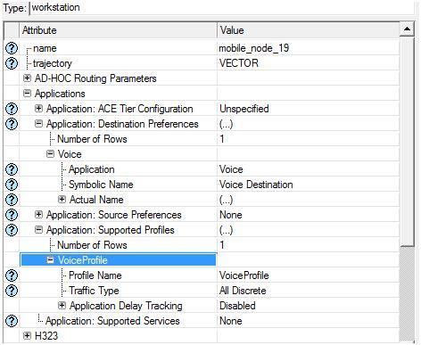
  • The total number of tows that are explained as single nodes requires support to the voice applications that are created with in the below screen

Application destination preferences is set to one rows and then the voice application is selected for this row and the symbolic server name is given as voice such that this server will generate the required voice traffic and the corresponding packets across the network.  Apart from the destination preferences now the application supported profiles are also set and in this context a single row is added to the section application supported profiles and voice profile is selected for this row as shown in the above screen. With this the node level application and profile definitions are applied to all the mobile nodes and the procedure followed to apply the same for wireless LAN server is given below

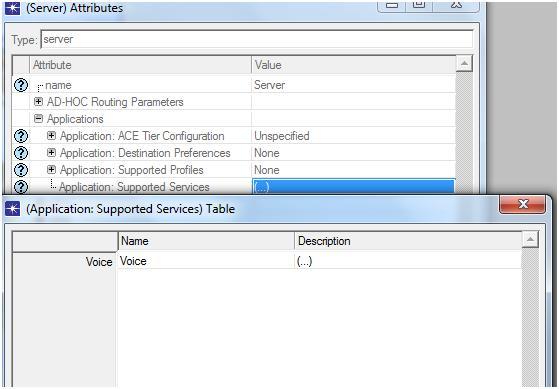
  • Select the wireless LAN server from the network and open it in the edit mode
  • There is an option like application supported profiles and expand this option to edit the profile settings for the wireless LAN server and the corresponding screen is as shown below

The above screen it can be identified that the voice profile which is been chosen as the main application facilitated and managed by the corresponding profiles the WLAN server will provide its support to the traffic that is distinct and then the voice profile will be generated and then the server will be capable of managing different types of the packets that are adjacent to the traffic. There is an alternate method which can be used to apply for the applications as well as the profile settings for the purpose of mobile nodes and wireless LAN server this particular process is known as deployment and these steps are explained in detail below:

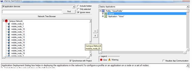
  • The user should go to the protocol menuàApplicationsàDeploy in order to define the applications
  • The new window is been displayed towards the user side and then the deployment process will be performed
  • The entire mobile nodes are been submitted towards the source and then the WLAN server is been submitted towards the destination side and the example is given below

From the above screen it can be identified that the entire mobile nodes are submitted towards the actual source. A success message like consistency check pass is displayed to the users if the deployment is done in a right manner. With this the corresponding email application and email profile are applied to the 20 mobile nodes and the single wireless LAN server. 

Basic Network Setup to create MANET Using the OPNET Modeler

Basic network setup:

The explanation of the process that is involved in creating the basic network setup required for this particular scenario is done in this section.Using the OPNET modeler a MANET model is created and this is considered as the model family that is needed for the simulation. A campus that is simple is selected for creating the MANET and 1000X1000 square meters area is selected as the size of the network scale and the 10 mobile nodes considered are operated across the campus taken where the model family considered is the MANET for the model of simulation.

A blank scenario is established to create the campus network needed and this done by using 10 mobile nodes initially.These 10 mobile nodes are dragged from the object palette and placed on the work space these mobile nodes are considered as the wireless sensor nodes and in the time of the routing process these will nodes will move in random routes. These mobile nodes taken can be controlled using the sink node and a wireless LAN server node which is fixed is dragged from the object palette and dropped in the work space and this is considered as the sink node that can control all the 10 mobile nodes.

Then the network setup is said to be ready for supporting the traffic generation through the network but for this purpose an application is needed always, for this from the object palette an “application configuration node” is taken on to the work space for establishing the application needed. In this particular scenario three applications are created as they are required and the next section of this chapter explains the configuration setting required.

The applications created are supported by the profile definition and this necessary for the OPNET simulation and to create the profile a profile configuration node is dragged from the object palette and placed in the work space. In addition to these a mobile configuration node is also selected from the object palette in order to support the mobile configuration. The list of nodes selected from the object palette are listed below, all these nodes are very significant for the simulation procedure.

  • The sensor nodes needed are regarded as the mobile nodes and they are taken 10 in number.
  • One fixed wireless LAN server is taken as the sink node to control the mobile nodes.
  • An application configuration node is selected to create the application necessary.
  • A profile configuration node is selected for creating the profile definition needed.
  • A mobile configuration network is selected to apply mobility to all the mobile nodes.

             The further sections of this chapter explain the process of real configuration implemented for all the nodes selected.