Mechanical Approach of the GPS Navigation Robot Project

Mechanical Approach:

Kinematics:

The GPS Navigation Robot Project we have designed to traverse on all terrains is on the concept of getting support from all the sides and having the ability to move ahead. The dimensions of the robot are 1600*965*810 mm.                                                     .

Design of Wheels and Motors:

The locomotion of bot is designed with six wheels so that the stability of the vehicle is high and moreover while climbing the steps or moving in rough terrain it will be able to have more support. Wheels of diameter400mm and thickness200mm are used. The wheels with V-THREAD profiles are selected to meet the desired need to move in all terrain. D.C Motors with specification of 40kg torque and 150rpm are designed to meet the desired speed and the load ratings. Similarly in total there are six motors one for each wheel hence each wheel will be having independent drive. The motors are placed in the wheel hubs supported by c-clamps.

Mechanism of Linkage:

          Kinematic of bot has three linkages in total. Each linkage supports two wheels. The front two wheels of each side are connected by one linkage and the rear wheels are connected by another linkage. Each linkage is designed on the concept of Double Rocker Mechanism. According to which there are two cranks connected to the main link. Similarly in this model the two C-clamps which are connected with the main link and the wheel acts like crank. Due to the presence of this type of linkages there is no separate suspension mechanism needed. At all point of times and at all positions always all six wheels will be touching the ground. This is the most advantageous point of having linkages.

 Double Rocker Mechanism

          In the above diagram A and B are the two cranks and c is the main linkage which is shown in the Double Rocker mechanism.  

FIG: shows the linkage in connection with the wheel

Steering Principle:

Apart from six D.C Motors, four servo motors are placed in between the C-clamps and linkage except the two middle wheels. So the wheels can be turned in any direction. The wheels if properly turned to the required angle, the entire vehicle may completely turn in its position up to 360°.The directional gyro which is of electronic model when fixed in the correct axis can find out how much exactly the wheel’s angle is displaced. Hence when the wheel has been turned to the required angle the action from the micro controller can be given to cutoff the voltage to the servo motor there by removing its action.  As each wheel has independent drive hence while turning the differential drive is obtained by giving variable supply to motor.

Material Selection of Chassis and Other Surfaces:

The chassis is the platform for electronic and mechanical tools. The chassis which should be light in weight as well as having high load capacity should be selected. Hence it was designed to use CNC Titanium or EPO resin.

 The two surfaces which are extruded from the chassis are shown transparent in the diagram drawn in the   pro-e modeling. This is due to the fact that both the surfaces are made of a transparent glass fiber made of carbon composite so whatever changes or deformations taking place could also be easily identified and rectified easily. Antenna is placed in the rear end, while the camera setup is placed in the front end. The camera setup has both stereo and C-MOS camera.

Robotic Project Report and Documentation

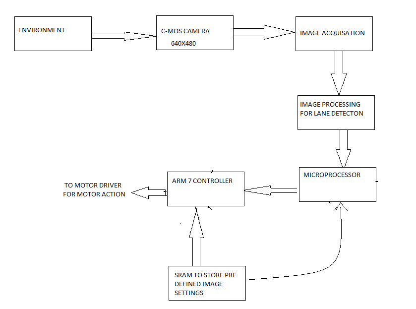
The following algorithm for robotic project report & documentation describes the sequence of operation for both lane detection and obstacle avoidance using Image Processing Analysis.

For Lane Detection:

STEP 1: Initialize the camera.

STEP 2: Take the different orientation of the given lane and pre-process the image and store it in the SRAM.

STEP 3: Now allow the camera to traverse the lane.

STEP 4: Take the snap of the lane and check with the data base.

STEP 5: Perform the controller action.

STEP 6: Repeat the process till the destination is reached.

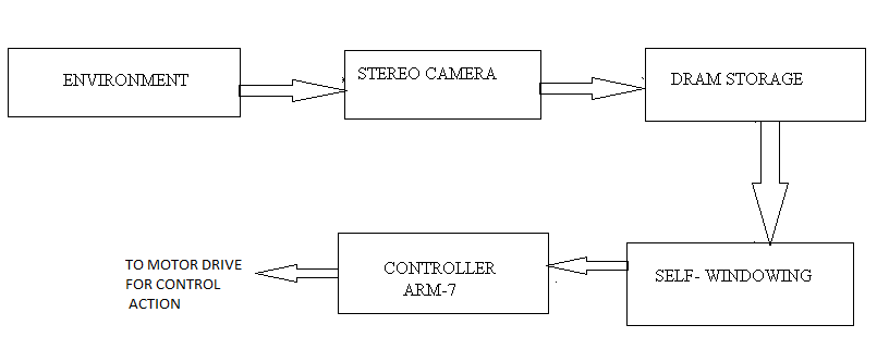
For Obstacle Avoidance:

STEP 1: Initialize the camera.

STEP 2: Observe the environment.

STEP 3: Store that in DRAM.

STEP 4: Do self windowing technique and determine the least pixel rate by using the analysis.

STEP 5: Allow the controller to take the action.

STEP 6: Repeat the process till the destination is reached.

Robotics Final Year Project Ideas and Topics

Constructional Working of Robotics:

Electronic Engineering ECE Approach:

Camera:

In our Robotics Final Year Project we have two cameras

a) C-MOS camera sensor

b) Stereo camera

          The C-MOS sensor camera is placed at the center of the bot and the stereo camera is placed at the center of the bot and the stereo camera is placed at the top of the bot. the camera is tilt to an angle to make the projection perfectly projected to the center of the object.

The C-MOS camera is used to perform more specifically for the lane detection. It is used because of its very high sensitivity to light, low power consumption and low cost. The output is digital, so it is directly fed to the controller to take the action. The functional block diagram shows the importance of camera action.

Technical Features of the Robotic Camera:

The Image processing and Image acquisition is performed by the on-board micro processor and the result of stereo and C-MOS camera is stored in SRAM (Static Random Access memory) and DRAM (Dynamic Random Access Memory) respectively.

The lane following is pre processing method, so the sample of images are pre loaded to the SRAM and it’s been cross checked by the controller and necessary action is given to the end effector. 

          The Dynamic image processing is carried out by using stereo camera where the self-windowing algorithm is used for real time variation. It is been stored in DRAM and synchronously signal is given to controller to perform the end- effector action.

Block diagram of the robotic project idea clearly show the importance of two cameras.

For lane detection:

For lane detection

Obstacle avoidance:

Obstacle avoidance

 Stereo camera is used for obstacle avoidance performances, since it has very high resolution.

Implementation of Fuzzy Temperature Control Using Microprocessor

Fuzzy Temperature Control Using Microprocessor project is designed as a system which can control the temperature of the devices using the basic fuzzy logic, this application checks the current temperature and checks weather it exceeds the desired limit, if then the application informs the user about the limit has been exceeded using an message send via SMS. This report discusses about the various components used and how they are been designed in a PCB.

Fuzzy logic controls are based on the theory of fuzzy set. Since the increased use of embedded system and microcontroller fuzzy logic has become more popular. Fuzzy logic is classified as a high level programming paradigm. Which is more appropriate for the embedded system when digital information processing is been used in case of microcontrollers. The main characteristic of fuzzy logic is that it transforms the binary world of computing into a computation basedon continues intervals of time. These property is been used by the embedded system.

The coprocessor design can be more costly than a software solution on a standard microcontroller. Another technique implemented in fuzzy logic is resolution analysis. The major reason for the fast execution of fuzzy logic in microcontroller is that it lies in identification of intelligent shortcuts during the compilation time itself in the PC. Some of the main advantages of fuzzy logic control are: High level linguistic variablebased control task description; it can beused for linear and nonlinear control, suitable for microcontrollerbased systems, Easy to implement multiinputmultioutput control system. Some of the main devices used in this project are LCD, program counters, Memory control unit, keypad, isolation circuits, power amplifier, ADC (analog to digital converter), buzzer, and LM35 microcontroller.

This paper also discuss about the whole device  with their pin diagram such as ADC 0809 controller IC and their working related to the project. Global system for mobile communication (GSM) are also been related to this project since the report are to be send to the user through the SMS service provided by the GSM architecture. 

Download Implementation of Fuzzy Temperature Control Using Microprocessor.

Design and Implementation of a Practical Aircraft Position and Reporting Identification Beacon (PRIB) in MATLAB

Design and implementation of a practical aircraft position and reporting identification Beacon project is a MATLAB project. Main aim of this project is to develop a new method for tracking aircrafts which does not depend on transponders. In order to develop this system we are using PRIB (practical aircraft position and reporting identification beacon) technology. In order to replace existing transponder system new system should fulfill size, cost, and power efficient and satisfy financial constraints. PRIB technology works on GPS technology in which GPS receiver will track aircraft signals and send to base station which is located at different locations in the form of radio signals. In this paper we provide detailed explanation on design and manufacture of PRIB. Performance is compared between existing transponders and PRIB system and detailed report is provided.

This application uses Gaussian Minimum Shift Keying (GMSK) modulation technique which is one of the secured and efficient modulation techniques used in wireless communication system.

In existing system transponders are used for tracking aircrafts which had shown few issues in recent years mainly at the time of terrorist’s attacks using aircrafts. These transponders can switch off deliberately and stops tracking aircraft for a base station. In order to solve this problem a efficient method need to be developed.

In present system we use PRIB based system which can work without depending on transponders. This system works on GPS technology which is secure and cost efficient.

In this project we provide detailed explanation on topics like aviation survey, global position system and modulation, hardware implementation, software implementations, measurements and experimental results and future development.

Download Design and implementation of a practical aircraft position and reporting identification Beacon project is a MATLAB project report.

Electronic Safety Assistance for Blind Using Micro controller and Dsp Voice Processor

Introduction:

The main objective of this project is to provide safety for blind people from obstacles. This device ensures safety for the blind while walking. The device is to be carried by blind and when the device senses any obstacle it gives the message through voice processor and accordingly he can move. The entire design is built on the concept of embedded system and AT89C52 microcontroller is used which monitors the components.

Circuit design and working:

AT89C52 microcontroller is the heart of the design. The IR waves are transmitted into free space and when these touch the obstacle its gets reflected. The reflected waves are receives by the IR receiver. The demodulator is used to process the signal and it gives the processed signal to the microcontroller. The microcontroller then drives the relay connected to the dsp voice processor by which the blind person can come to know about the obstacle. The microcontroller is provided with an oscillator frequency of 12mhz, and a reset logic signal is fed to the microcontroller so restart when bugs occur. The entire circuit is provide with an rechargeable battery source. The advantage of selecting AT89C52 microcontroller is that it has an 8kb of flash memory. The relay is to drive the dsp voice processor according to the given signal.

Advantages:

The device is very helpful for the blind people to go in a exact path without the help of others. Instead of using IR signals we can also use light signals detecting obstacles. The IR signal response for after the detection of obstacle is delayed by 0.2 seconds which is to be overcome.

Download Electronic Safety Assistance for Blind Using Micro controller and Dsp Voice Processor.

Electronic House Project Abstract

Introduction to electronic house:

The main aim of this project is to save the power in a house hold environment. We will employ certain techniques to reduce the usage of power. In this we are six major equipments which are use monitor all the devices present. By using this model we can have a monitor control over the devices.  All the monitoring equipments are controlled using a remote controller. The six equipments are

Remote operated gate control;

This is used for opening and closing of the gates, it has a sensor placed in front of the gate which gives us the signal on the remote so that we can operate the gate. By using this we can provide safety to the house.

Auto adjustable timer unit:

By using this timer unit we can set the time control for the working of the devices , after the completion of the time the devices gets off. This is used to set time control for devices like water sprinkler in garden, and bed lights etc.

Remote operated appliances:

This is used for controlling the devices like fan, ac, tv ,washing machines etc. All these appliances made on or off by using the remote control.

Touch sensitive burglar alarm for internal security:

This is used for providing internal security to lockers and some cupboards. The sensor placed for these things gives an alarm when touched by a un identity.

Automatic gate light and bell system:

This device is to give  a bell and puts on lights when the person is entering. By this we can the power by reducing the unnecessary use of gate lights. From the automatic bell we can know when any one is coming.

Water level indicator and controller:

By  using this we can know the level of water in the tank and it automatically puts off the pump when the tank gets full. By using these equipments we can save the power.

Download Electronic House Project Abstract.

Electronic Components Tester Project Report

Introduction:

The main objective of this paper is to design a device which can test the electronic components accurately. In this paper we will discuss the testing of electronic components and how to repair them. A multi meter like device is designed by using a 8051 micro controller. By using this we cannot know the operational parameters of the device but we know only whether the device is working or not.

Micro controller working:

We will select an AT89C52 microcontroller which comes under the family of 8051. It is an low power and high performance 8 bit cmos microcontroller. The special feature of this microcontroller is that it has 8kb of internal flash memory which is not available in most of the microcontrollers. It is a powerful and highly flexible for the design of embedded control applications. It is a 40 pin device in which 32 pins can be used for input and output purpose and it has 256 bytes of ram. It has idle mode which halts the normal execution and allows the interrupt to continue execution.

Testing process:

An IC555 timer is used to generate a pulse which is used for testing the electronic component. The pulse is fed to the input line of the micro controller. A control unit is present in the circuit so as to adjust the pulse frequencies accordingly. At the output line of the micro controller we connect the electronic components to check its working. We can see the output values in the lcd. By using this device we can check the working of transistors and diodes. The present available multi meters have only specific capability of checking only diodes or transistors. We cannot know the operational parameters of the components so cannot know at what point of value the component cannot work in the circuit. Thus we can conclude that this device is high performance capable and low cost when compare to that of available multi meters.

Download Electronic Components Tester Project Report.

Electronic Circuit Breaker System

Introduction to circuit breaker:

Circuit breakers act like switches which detects the faults occurred and stops the flow of current by saving the equipment from voltage overflows and short circuits. It can automatically come back to working when the faults are rectified. Generally the faults in the circuits occur due to in continuous flow of current or by improper arrangement of load elements. The circuit breakers can be designed accordingly for lower voltage circuits and higher voltage circuits. An AT89C52 micro controller is used for monitoring the circuit.

Circuit design and Working:

The microcontroller is fed with the rectified voltage coming from the rectifier. All the load elements are connected to a relay switch.  The microcontroller monitors the voltage level required for the load elements, if it detects any change  the voltage levels to voltage fluctuations  then it automatically drives the relays to turn off. The rectifier bypasses the voltage levels and then the microcontroller again makes the relays turn on. These circuit breakers are mainly used as regulators in power circuits and in battery shunt circuits. The advantage of 89C52 is that it has a 8kb of flash  memory which can be reprogrammed any number of times. A step down transformer is used to obtain the required current for the load elements present.

Advantages:

The circuit breakers are very effective in protecting the load elements from voltage over flows an short circuits. It can automatically switch when the faults occur, where as a fuse cannot switchover. It can be used for lower voltage circuits and higher voltage circuits. It is low cost model when compared to other circuit protecting devices. 

Download Electronic Circuit Breaker System.

Electro active Polymer “Artificial Muscle” Operable In Ultra High Hydrostatic Pressure Environment

Introduction:

Electro active polymers can withstand high present in the deep seas. These polymers are used as skins for devices so that the devices with the pressures in the under water. Electro active polymers have benefits of high coupling efficiency and low cost of availability. The electro active polymer shows good characteristics even under pressures upto 100 mpa. In this paper will see the design and the experimental testing of the polymers.

Brief on electro active polymers:

These are used as transducers for high power sonar’s so as to undergo high pressures. The electro active polymers are prepared from elastomeric actuator. These actuators are formed from two flexible elastic electrodes which sandwich an electrically insulated elastomeric. When the voltage is applied in between the electrodes the get squeezed and expand in area. These have high coupling efficiency because of low visco elastic loss and electrical leakages. It has specific density energy of 21 times that of single crystal peizo electric and can withstand maximum strains.

Experimental testing method:

Here a medium size  water tank is used in which high pressures are generated. Here the maximum pressure can be 159 mpa and has a supply voltage of 2.74 mpa.  It has a flexible transparent membrane which can exert pressure on the polymer. The device is placed in a box and is sealed with silicon oil.  The box is placed in the tank which generates the deep sea conditions. A camera is placed in the tank to monitor the active region. By increasing the pressure levels upto 100mpa the strain a measured. By using a micro meter capler the conditions of the active region for different supplied voltages are measured. As the pressure does not make the polymer to show any changes then we can use it for sonar transducers.

Download Electro active Polymer “Artificial Muscle” Operable In Ultra High Hydrostatic Pressure Environment.