Development of a Repository and Search Engine for Alumni of College Rase

Introduction to Development of a Repository and Search Engine for Alumni of College Rase:

An alumni association refers to an union of graduates (alumni) or former students. The students of  universities, colleges, schools, fraternities and sororities make a group with the alumni from the same institution. Social events are conducted, newsletters or magazines are published to generate funds for the institution.These alumni organizations are chiefly conducted at universities or departments of universities or may be conducted amidst students who studied in a particular country. Previously, alumni associations were regarded as the old boy network  but nowadays they include graduates from any age group and demographics. 

This project’s objective is to create a repository for a college’s alumni which is of great significance to the institution. The Repository and Search Engine(RASE), an Internet based application, can be approached round the globe. This enables the users to access the Search Engine to gain information about the college alumni but they cannot be added. The database can be updated only when the alumni belongs to that institution. 

The project is supposed to be finished in two stages. The first stage would include the development of a simple system which would be employed to gather data from the students of the present final year prior to the end of their term. The second stage would involve the working of the system that would enable the passed out alumni to get registered.

 Hardware Requirements: 

An Intel Pentium IV or later Processor, a RAM of minimum 512 MB, a Secondary storage of 80 GB is required. 

Software Requirements: 

An Operating System Server: Windows XP or later, a Database server : Oracle or MYSQL, a client :Microsoft Internet Explorer, tools and environment: Apache Tomcat 1.6, JDK 1.6, a user interface:Html, Jsp and a code behind: Java, Jdbc, SQL are required.

Download Development of a Repository and Search Engine for Alumni of College Rase.

Dynamic Search Algorithm in Unstructured Peer-to-Peer Networks Project Abstract

Introduction to Dynamic Search Algorithm in Unstructured Peer-to-Peer Networks Project:

In unorganized peer-to-peer networks, creating effective search algorithms is a major challenge. Two usual types of search algorithms include flooding and random walk(RW). Flooding conducts an aggressive search that involves utmost nodes. As it produces several query messages, it can’t be scaled. On the other hand, RW conducts a conventional search and produces a limited query messages but consumes a lengthy search time.

Therefore Dynamic Search(DS) algorithm is suggested, which is a  generalized form of Flooding and Random Walk. When it comes to short-term search, DS follows flooding, whereas it follows RW during long-term search. In order to refine the performance of the search, DS unites with the knowledge-based search mechanisms. The performance of DS is calculated by few performance measures such as success rate, search time, query hits, query messages, query efficiency etc. As shown by the outcome, DS offers  a good tradeoff  within performance and price. According to the power-law graphs, DS functions 25 times better than flooding and 58 times better than RW  and as per the bimodal topologies, it functions 186 times better than flooding and 120 times better than RW. 

Dynamic Search algorithm has benefits such as reduced search time and combines both flooding and random walk technique. These algorithms take the benefit from the knowledge gained from the earlier search outcomes and on the basis of the knowledge, they route query messages with various weights. 

Hardware Requirements: 

The hardware requirements include any Processor above 500 MHz, a RAM of 128 Mb, a Hard Disk of 10 Gb, a Compact Disk of 650 Mb, a standard keyboard and  mouse and a VGA and High Resolution Monitor as an output device. 

Software Requirements: 

The software requirements involve Windows Family as an Operating System, JDK1.5 as a Language, Microsoft Sql Server as a Database and Java Swing as Front end.

Download Dynamic Search Algorithm in Unstructured Peer-to-Peer Networks Project Abstract.

GSM Based House Maintenance and Security System Project Report

Introduction to GSM Based House Maintenance and Security System For Legless People Project:

The security of one’s home while its occupied or in their absence is a cause of concern for us. The advanced technology has allowed us to safeguard our home from wherever we are. Gsm based house maintenance and security system for legless people has proven to be a blessing to the legless people as they can control and check their homes from any place with the help of their mobile phones. This acts as a helping aid to them in a dual way. Firstly, they can take care of their house even when they are away from it and secondly, it helps them safeguard their house, that is, both purposes are served- house maintenance and security system.

With the help of a microcontroller and a relay circuit, house maintenance is attained. The microcontroller when acknowledged by the authorized person operates the electrical appliances by switching them on and off and displays their current working state. This process can be carried out through the mobile phone of the authorized person.

The second purpose, providing security, is served by an alert message which is passed to the owner, in case of any foreign intrusion. In emergency situations, the security alarm system is used to inform the owner about the intrusion. The system also allows the owner to send messages to the system to enable or disable the alarm.

Gsm based house maintenance and security system for legless people is a really useful tool for the physically challenged people as they can maintain and safeguard their homes even when they are away from them, without putting much effort and money as it is not much expensive either.

Download GSM Based House Maintenance and Security System Project Report.

MS Dissertation Project Screen Shots for Distributed Networks Project

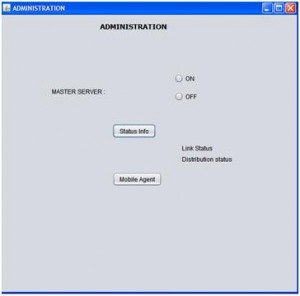
The project begins with the administration module and as discussed in the previous chapter, administrator are provided with an window and from there they can perform the required operations and the actual window created using the coding is as shown below

From the above screen it can be observed that the administrator is provided with an option to start the master server from where the actual operations begin. Administrators are also provided an option check the status of the network and with respect to this link status and distribution network status can be checked in this module and also the administrator can start the mobile agent by clicking on the mobile agent button as shown in the above screen. 

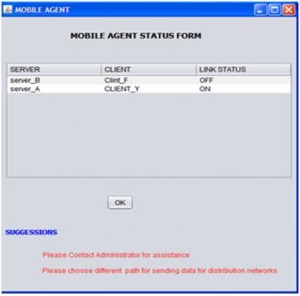
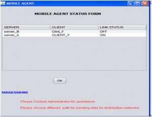
From the above screen it can be observed that the mobile agent module provides the required information related to the link failures and the corresponding information is displayed to the users in the form a table and the corresponding suggestions with respect to these failures are also shown. This module is actually invoked when there are faults across the network and the corresponding faults and network operations are shown below 

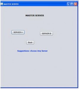
When the administrator click on the start master server this particular window is displayed and it can be observed that users are provided with the option to start the Server A and Server B. When the user clicks on the Server A, server A is started and the same with the case with server B and the next steps are as given below 

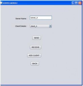
When the user clicks on the server A button, the screen shown above is displayed to the user and from here the actual server operations are initiated. It can be observed from the above screen that users can select the desired client from the list of clients and proceed with the required operations. The users are provided with the options like Send, Receive and Add client and they can click on the desired button to proceed with the required option and the corresponding screens are as given below 

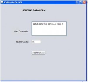
From the above screen it is clear that the users can send the data from the desired server to the desired client and the actual number of packets being sent is also calculated before sending the actual data to the desired client or server. The data sent is saved in the datapackets table as described in the previous chapter. 

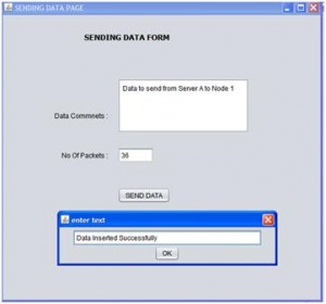
Once the data is sent to the desired client or server, users are shown a message with respect to the data insertion and thus one can conclude that the data is sent to the desired client or server successfully.

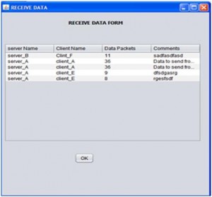
All the data received is displayed in the form a table and is as shown in the above screen. This table contains the key columns like server name, client name, number of data packets sent and the actual message sent. This table can be used to track the log of received data by the administrator and also check the level of communication between the clients and the corresponding servers. 

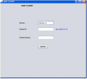
This screen shows the procedure to add a client to a particular server and if the users selects the server A to add the client, then the server A is populated by default on the server field and the users can add the client IP address and the client name. This client is added to the particular server if the server has the limit to handle the required number of clients.

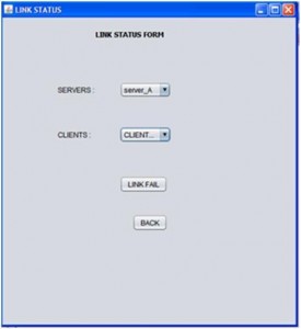
This screen shows the link status form and the users can select the desired server and the corresponding client to fail the link externally. This can be considered as the required fault across the distributed systems and if the server and the client are required and once the link fail button is clicked, then the corresponding link is failed and the communication among these nodes is not possible further and the users should contact the administrator and select an alternative path for the communication as shown in the mobile agent window. 

This screen shows the mobile agent screen where it displays all the nodes that were failed and  now the administrator can select the desired client and server and set back the status as either on or off as shown in the above screen. If any link between the server and client is off, users are provided with an option to contact the administrator for assistance and also they are suggested to choose an alternative path for the communication as shown in the above screen.

This paper is written and submitted by sai

Introduction To Distributed Communications Networks

Distributed networks are widely used across the networking world these days and the main popularity of these networks mainly is due to their wide range of support to the distributed applications and nodes across the networks. Parallel computing and distributed computing are the previous modes of the distributed networks and where the distributed networks can handle multiple servers and clients.

A single server can handle multiple clients and each and every client can process the data requests from any of the server. The load on the master server is reduced a lot with the help of distributed networks and there are few limitations with the distributed networks as well and the key among them are the faults occurred across the network.

In general there are different faults that may occur across the distributed networks and the important among them are link failures and the distributed mode of the network is down for some time. At these scenarios the communication among the nodes of the distributed networks are on halt and even the adding the clients and servers to the distributed networks are also stopped and thus the overall performance of the distributed network is affected a lot.

There are many fault tolerant techniques available across the literature and most of them are static in nature and can’t gather the required information with respect to the link failures.

This paper is written and submitted by sai

MS Dissertation Topic on Distributed Network for Detecting Faults across Network

The main aim of this MS Dissertation project is to evaluate the role of mobile agents in detecting the faults across the distributed networks and incur the fault tolerance techniques across the networks. To prove the proposed concept, Java based application is used in this project and the corresponding design is given in this project. A master server is used in this project and this server can handle two servers and each server considered can handle a maximum of two clients.

A distributed mode to the network is also provided in this project, where the newly clients are added to the next server if the maximum limit of the servers are done and in this way the load on the server is reduced a lot. Java Swings are used to design the user interface and the corresponding implementation procedure is given in this project along with the key discussion to important code is also given and a detailed evaluation to the results is also given.  From the detailed analysis of the results it is clear that there could be many chances for the faults to be occurred across the distributed networks and these faults can be in the range of link failures or distributed network failures.

All these link failures are identified by the mobile agent and displayed to the administrator at any point of time and this information is captured using a perfect database and now the administrators can handle these issues immediately by either setting the link status to ON or suggesting the users to choose an alternative path for the communication to happen. Few distributed network options like adding the clients and servers and sending the information to the desired clients and servers are also provided in this application.

Thus from the overall analysis it is clear that distributed networks are porn to faults and a perfect mobile agent can handle these faults and set back the network on state and ensure each and every client is always connected to the desired server even in the case of faults as the mobile agent can handle all the faults in an efficient manner and even the load on the servers are also reduced due to this mobile agents. The traditional handlings of faults across the distributed network are resolved using the mobile agent based approach. 

 Future work 

Apart from the work done against proving the importance of mobile agent in detecting the faults across the distributed network, future work can be done in this application to improve the scope of the application and it is listed as well. 

  • A detailed evaluation to the mobile agent methodology can be done in future to improve the quality of finding and detecting the faults across the distributed networks
  • Few real time simulation tools can be used to evaluate and compare different agent based fault tolerance techniques across the distributed networks
  • More number of servers and clients can be added to the application to understand the real impact of load on faults across the distributed networks.
This paper is written and submitted by sai

Mobile Agent Based Fault Tolerance System Implementation Procedure in Java

The actual procedure followed to implement the proposed design as mentioned in the previous chapter is explained in this chapter. As mentioned the proposed design is implemented using Java and the all the required screens are designed using the Java swings and the data base is created in Oracle SQL. This chapter summarizes all the important classes and tables used along with the flow of the application are clearly described in this chapter.

Classes used in the application

Every aspect across java programming is an object and these objects can be inherited in the form of class and the objects of the class can be created to initiate the core functionality used across the class. Following are the classes created in this project with respect to initiate the flow of the application. All the classes used across this application are created using the Java swings framework and the flow of the business logic is as listed below

  • AddClient.java
  • Administration.java
  • CommonUtil.java
  • First.java
  • LinkStatusForm.java
  • MasterServer.java
  • MobileAgent.java
  • ReceiveData.java
  • SecondFrame.java
  • SendDataForm.java
  • ServerModule.java
  • UKprogg.java

All the java files are created with an extension of .java and the corresponding logic used across these java files are as given below 

AddClient.java 

Required logic to add the clients to the servers is given in this class. As per the design few clients can be added to the server and the corresponding procedure is coded in this class. Java swing frame work is used to create this logic and all the basic components of the swing class like text fields, layouts and gaps are used to create the basic layout out the of the screen and is as shown in the appendix section. A separate client id is issued to the newly added client and assigned to the desired server and the corresponding logic used here is that the server id is tracked against adding the required client and the newly added client is to the serve and the server is identified with the server id. Once the client is added, a new row is added to the client table and the corresponding query used here is Initially the number of clients are calculated and if this count is as per the defined handled clients for the server, then only the client is added to the desired server else the client is added to the next available server.  Once the required constraints are satisfied the client is added to the client table and the rows are incremented by 1 against the table.  Whenever the client is added to the server and the database is updated, the link status of the server and the client is also updated and set to on the corresponding logic is written.

When the client is added to the server, the corresponding client IP address and the client name are also updated against the database table client. 

Administration.java 

Administration.java class is used to create the user interface for all the administration activities and the coding procedure followed is explained in this section. The key administration tasks used in this project are to start or stop the master server, check the status of the links, start the distribution mode of the network and initiate the mobile agent for detecting the faults across the distributed networks. Administrator can check the status of the links between the clients and the server at any point of time and they are provided an option with respect to this.  A link status form is opened at the user interface and the administrators can view the status of the desired links at this window and even this window is created using the swings. Distributed network option is also available to the administrator and they can initiate the distributed mode of the network.  Admin is provided with an Mobile agent button and the users can click on the button to start the mobile agent, where this agent collects the information related to the distributed network faults and suggests the options for the fault recovery options. The key java code used to create this logic is as given below 
A new object is created in the private methods to initiate the administrator requests and thus the overall functionality of the admin module is coded in this java class.

CommonUtil.java

This class is used to created the frequently used java functions like the database functions and thus if at all a new instance of the database is required an object is created for this class and initiated to dump the complete coding logic in this case.  Following are the important methods used in this class and the corresponding description of the methods are also given below

getConnection

This method is used create the connection to the database and the basic JDBC drivers are used to create the connection to the database using the Connection class across java. Once the connection is established, the corresponding statements and other parameters are initiated. Oracle thin driver is used to create the bridge to the database in this class and the user name and password to access the database are also provided in this method

getServerNameByServerId 

This method can be used to get the server name by providing the server if as the required parameter.  A separate global server is used as the required table and the server information is recorded in this table and thus the information is fetched from the database and the corresponding query used for this process is as given below 
getServerIdByServerName 

This method can be used get the server  name by providing the server name as the required parameter and the value is fetched from the global server database table. Following is the query used to get the required information from the table 

getClientIdByClient_name 

This method can be used to fetch the required client id with the help of client name and the client name is provided as the required parameter to the method.  Below is the query is used to get the required client information with the help of client name 

getClientNameByClientId 

This method can be used to get the client name by providing the client id as the required parameter and this name is fetched from the database table known as client and the actual query is used in this context is as given below 

LinkStatusForm.java 

As mentioned the administrator can check the status of the links from the desired server and the client and the corresponding code is given in this java class. User interface is provided in such a way that the users can select the desired from the dropdown list and also can select the client id from the list and the swing components are used to create this interface.  All the ids of servers and clients are fetched from the corresponding database tables and the required logic is given in this class. Once the users selects these values, these values are given as the input to the query built and this query is fired on the status table to get the current status of the desired server and client and the corresponding coding logic used is as shown below 

Thus the current status of the client and the server can be fetched using this logic and the query as shown above. 

MasterServer.java 

Master server is initiated across this project and the corresponding logic used is given in this java class. From the master server user can start the desired server and in this project two servers are created and named as Server A and Server B and once the user clicks on the desired button, the actual server operations are started. Java swings are used as the required framework and all the key components are added to get the required interface to the application. The actual action performed by user is captured using the action events provided with the swings package and based on the action performed the corresponding server is started and the key coding logic used in this context is as shown below 

From the above code it is clear that if server A is selected the corresponding ID is tracked and the actual server module is started and this procedure is repeated for both the servers as shown in the above code. 

MobileAgent.java 

This is the important class used among all the classes created in this application. Mobile agent is the java class that captures all the link failure information and displays to the administrator and the administrator can set the status to On again using this class and the corresponding functionality used. User is also provided the required suggestion to check the alternative paths across this process and the corresponding functionality is provided in this class. The link status information is fetched from the database and the corresponding logic is used as given below 

 From the above code it is clear that the required information is gathered from the database table link_status and the status values are iterated in a loop using the result set object available with the JDBC package and the fetched values are displayed to the users in a tabular form and required rows are added to this table using this information fetched from the database table.  A vector object is used to store all the values retrieved from the database and the loop is iterated against this loop. 

ReceiveData.java 

As mentioned in the design of this project, clients and servers can receive the data from the any other servers and clients and the required programming logic is given in this java class. All the data received from any other client or server is displayed to the users in the form a table and the required logic is written using the java swings framework and the corresponding components in the swing framework. Database connections are established to gain the access to the information related to all the received data by a particular client or server. A table with name datapackets is created in the database and that particular information is gained from this table and displayed to the users in a tabular form. All the data received is fetched from the table and stored in a vector object and thus a loop is iterated using the JDBC result set object and the corresponding values are displayed to the user and the corresponding screenshot is as shown in the next chapter. The actual coding logic used for this java class is as shown below 

SendDataPage.java 

As mentioned in the design chapter, any client or server can send to the desired client and server and the required programming logic is created in this java file. A window is created across this section and the users can type the desired message to be sent and actual number of packets is also calculated using this logic. A separate text field is created in this class and the client or server can add the required message to the text area and the data entered is sent to the desired client or server and the number of packets sent is also calculated in this class and the corresponding coding done is as given below 

From the above code given it is clear that all the data sent is saved in the database table datapackets  and the inserted text is converted to the desired format and the corresponding client and server information are added as well. A prepared statement is created and the query is inserted to the prepared statement and executed to insert these values in to the database table. 

Following are the database tables used in this application

  • Globalserver
  • Client
  • Link status
  • Data packets 

All the important classes are explained in this chapter and the corresponding code is also provided. The actual results achieved against this implementation are given in the next chapter. 

Mobile Agent Based Fault Tolerance Module

Once the failures are detected, now the users can choose the mobile agent based fault tolerance option to detect and rectify these failures.  A separate mobile agent is maintained in this application that will detect the failures from the database table and also suggests the corresponding solutions to these options. Users can click on the Run agent button to suggest the possible solutions to these failures and they are as explained below 

If there are any link failures to the network, this agent will suggest the alternative links and this could be something like if there is a failure from Server A to any other client, this mobile agent will scan the network and suggests alternative links to the client or server via other clients or servers. Now the users can choose the best alternative to set the link up and once done the link status is set to On and the users can proceed with the communication. 

If there are any distributed network failures and users cant use this option, the corresponding mobile agent can rectify this issue in the following way. Now the mobile agent will add more servers to the application and add the new clients to those servers on a temporary basis and ensure the distributed network option works fine and will delete these servers once the actual problem is rectified and the status of the distributed network is set to On and the users can use this option in a similar and previous manner. 

This paper is written and submitted by sai

Distributed Network Computing Model

To make this application a distributed network, a separate distributed network module is created in this application and few assumptions are made in this context. In this module, a predefined metrics are defined in this context like the number of clients to be added and the amount of data to be sent and if these metrics are exceeded then an alternative sever is chosen to add the clients and also process the client request and following are the conditions to be applied in this context

  • A sever can handle only 6 clients and if more clients are added to the server, these clients are automatically added to the next server
  • If both the servers has 6 clients each and more clients need to be added, an extra server is created and the new client is added to that server
  • Each server can process a maximum of 6 client requests to send or receive data and if this limit is exceeded, automatically the next available server is chosen in this context
  • All the servers updates the data to the master server as mentioned above

Client module

A detailed explanation to the server module and the distributed network module is given above and the design aspects of the client module are given in this section. As mentioned above, a single server can handle not more than 6 clients and these clients can communicate with each other or to their server or the other servers when the load on their corresponding server is high. Following are the key functions of the client module

Send data

Clients can send data to the desired server or client as per the requirements. Whenever the client wants to send the data, users are provided with the option to choose the desired destination and this destination can be either another client or server. Initially the users are provided with the list of options and these options only include the peer clients and their corresponding server and if any case the distributed network conditions are violated, users is given a warning message that the server is busy and now the users can choose another server to process their request. While sending the data, users are provided with a browse button and a text area field so that they can choose the desired file or write some request at the sending option and they can click on the send button to send the data. Once the data is send to the server or any other client, the corresponding details are stored across the database.

Receive data

Clients can receive the data either from the server or the client and to achieve this separate functionality is designed in this context. Whenever a client or server sends the data to a particular client, a separate link is provided to the users with respect to check all the data received against that client. Whenever the users click on the link, a table is generated showing all the details of the received data against the sender and the table contains the columns like sender Id, the date or time when the data was send and the description of the data. User can check the desired sender details to download the data and once done the data is saved across the database. 

This paper is written and submitted by sai

Project Design for Computer Engineering On Fault Tolerance System For Highly Dynamic Distributed Systems

As the main aim of this project is to design and implement a fault tolerance system for highly dynamic distributed systems using an agent based approach, the actual design implemented in developing this application is given in this chapter. A mobile agent based approach is followed to identify the failures across the dynamic distributed networks and a fault tolerant environment is provided across this approach. A detailed explanation to the front end and database design is given as below

Front end design

A virtual dynamic distributed network is created using Java in this project and to create a distributed network two servers and four clients modules are created in this project and these nodes are assumed to be in a distributed nature.  A single server module can handle two clients in this design and thus a total of four clients are managed by the two independent and distributed servers. These two servers are controlled by a master server module, where these two servers are the distributed sample of the single master server. The actual programmatic implementation and design aspects to create these modules are given as below

Master server

Master server is the key component in this process and can maintain the two independent and distributed servers. Master server is represented with a server icon and when this master server icon is clicked by the user; the actual functionality of the application is started. On and Off radio buttons are provided against the master server icon and when the user checks the On button two server modules are invoked and when the user clicks on the Off button, users are asked to choose one of the servers to terminate its operations. Once the On button is clicked, the actual process is started and it is explained in detail as below

Server modules

As it is already mentioned two servers are created and considered as the distributed servers and each server can handle two clients and in future more clients can be added as per the user requirements and this provision is also provided at the design level.  A server module is composed of few aspects and the detailed explanation to the server operations is as given below. A distributed server is represented by the server name like Server A and On and Off radio buttons are provided against the server icon. When the user clicks on the On button, the server operations are initiated and the actual operations are listed below.

Send data

Send data is the primary operation available for both the servers and this option is provided to the user across the server in the form a simple button. Whenever the user clicks on the send data button, a browse window is opened and the user can select the desired file to be sent from the servers. Once the file is selected, the very next operation is to choose the client as each server can handle two or more servers. In general the clients are identified with the client name or IP address. To simplify the concept a unique number is assigned to the clients and this number is assumed to be IP address of the client, as this application is a standalone and no network operations are included to simply the demonstration.

Once the client is selected, send button is clicked against the server icon and then the sending process is initiated and this process is represented graphically till the data is send to the client.  The number of packets transmitted to the client is also displayed to user. Users are provided with an option to check the total number of packets being transmitted before sending the data to the client and also can check the actual number of packets transmitted to the client. User can send the data to any of the clients by choosing the client unique ID as mentioned above and once the data is sends to the client, it is stored in the client database against the server name, number of packets send and the client ID.

Receive data

Servers can receive the data from the clients as well and to achieve this, a separate button is provided to the users against the server icon. Once this button is clicked server can select the desired client from where the data should be received and once selected the corresponding data is stored across the server database table.  Total number of packets received can also be calculated across this module.

Link status

Link status from the server to the client and client to server can be checked using module. Status of the link can be checked by clicking on a button before sending or receiving data and if the status is On, then the sending or receiving is done successfully and if the status if Off, the corresponding process are terminated.  Users can check the status of the link at any point of time and if anything goes wrong across the modules, the link status is automatically set to Off and this indicates that there are some failures across the distributed networks and these failures are detected in this project and an alternative fault tolerance system is developed to set the link status again On for a continuous communication mechanism.

Add clients

Users can add more clients with the help of the button available against the server icon and whenever a client is added to the network a unique ID is provided to the client and it can be accessed through the ID.  Once the client is added, a separate row is created in the database table and the client details are maintained in the table and sever can send data or receive data from the client added. When the Add client button is clicked by the user, they are provided with an option to choose the desired server to which the clients should be added. 

This paper is written and submitted by sai