Setting the application configuration
Defining the application definitions is the main step in this simulation as the required voice applications are created and the required Quality of service settings are done in this section. As mentioned in the above section, application configuration object is used and the required attributes for the application config are edited to set the application definitions. Following steps need to be followed in creating in the application definitions
- Edit the attributes of the application configuration by right clicking on the node
- Go to the application definitions tab as shown in the below screen
- Enter the number of rows as 1 such that in this scenario a single application is created
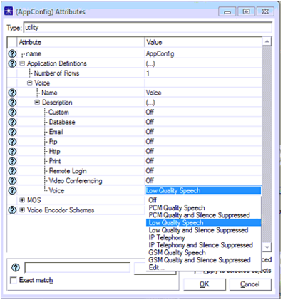
- Name the application as per the requirements and expand the application description tab to choose the desired application and the corresponding screen is as shown below
From this screen it can be observed that a low quality speech application is chose against the voice application and thus it indicates that this application supports a low quality speech in terms of quality of service requirements. This can be considered as the main step in defining the applications and in general there are different options available here and rest of the application types is chosen in the next scenarios. Now the Ok button is clicked to apply the low quality speech application to this scenario and the settings to be done for profile definitions are explained as below
Settings done for profile definition
There should be a profile definition for the application created and in this process a single profile is created for the low quality speech application created in the previous step and the settings need to be done in this context are given below
- Edit the profile configuration option by right clicking on the profile configuration object
- Give the number of rows as 1 for the profile configuration and name the profile as voice
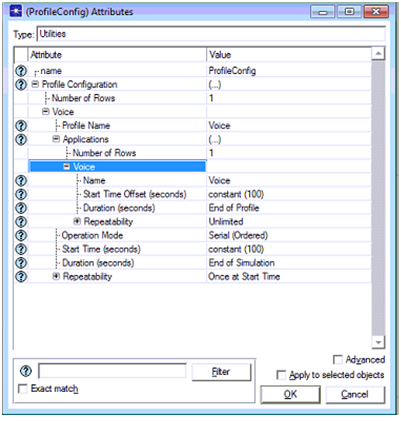
- Choose Voice application as the desired application to be supported against the profile definitions and the corresponding screen is as shown below
From this screenshot it is clear that the number of rows is given as 1 and voice profile is chosen as the desired profile. Voice application is chosen for the profile definition and the a constant value of 100 seconds is given for start time offset, end of profile is chosen as the duration of the profile, a constant value of 100 is chosen for start time and again the duration of the profile is set to end of simulation as shown in the above screen. Once the profile settings are done then these profile settings and the application settings need to be addressed to all the mobile nodes and the wireless LAN server and the actual process adopted in this simulation are given as below
Settings done for mobile nodes and wireless LAN server
A simple wireless LAN based MANET is created in this simulation and for this purpose all the WLAN workstations and server are edited for settings the attributes and in this context the process followed is explained in this section. First step in settings the attributes for the mobile nodes and the wireless LAN server is assigning the IP addresses for all the nodes and the following steps need to be followed to assign the IP addresses
- All the mobile nodes and the server should be selected from the simulation network
- Move the control towards the protocols menu and then choose the IP option
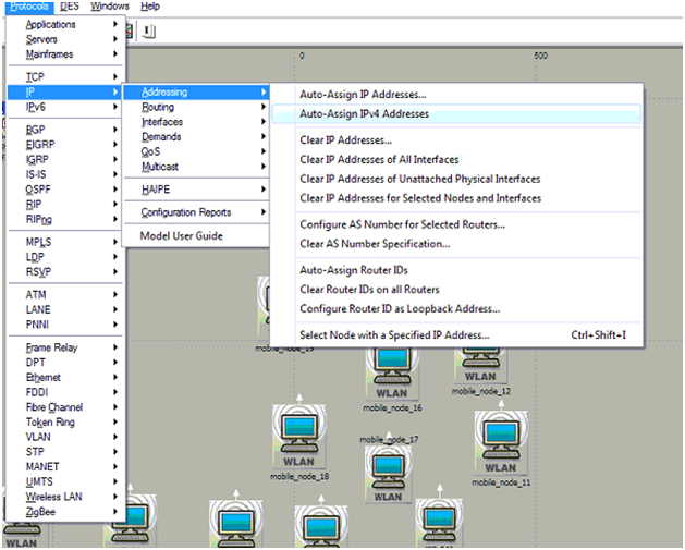
- There the users can find an option like addressing and from there choose the option Auto assign IPV4 addressing to assign the IPV4 addresses to all the nodes on the network and the corresponding screen is as shown below
With this step all the nodes and the wireless LAN server are assigned with the IPV4 addresses and thus all the nodes are identified with a unique IP address for the routing process. The next step in the simulation is to assign the desired routing protocol to all the nodes and the server and the steps that should be followed are as given below
- All the nodes and the server should be selected and then choose any of the node from the simulation network
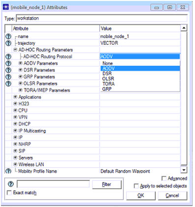
- Ad hoc routing parameters should be edited to set the required routing protocol as AODV and the corresponding screenshot is as shown below
It is clear that AODV is used as the routing protocol and thus now all the nodes and the wireless LAN server support the AODV routing parameters for the basic communication aspects. Now the AODV routing protocol plays the key role in delivering the voice packets to the destination. When the routing protocol is set to the desired nodes and the server, the application and profile settings need to be assigned to the nodes and the corresponding process followed is as explained below
- Select all option is chosen to select all the mobile nodes on the simulation network
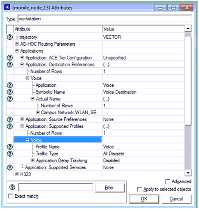
- Any one of the mobile nodes from the selected nodes is chosen and edited for all the application attributed by right clicking on the selected node and the corresponding process is shown as below
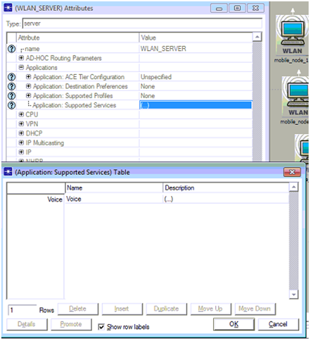
The application attributes of the selected node are shown above and from this it is clear that the application destination preferences is assigned with one row and voice is given as the desired the application destination and the voice destination is selected as the symbolic name. Application supported profile is set to one row and the profile name is set as voice and thus all the nodes across the network will support the voice destination and voice profile across the network by choosing apply to selected objects is checked for the settings. Similar procedure is followed for the wireless LAN server and the corresponding screenshot is given below.
A single row is added to the application supported services table and voice is selected as the desired option and the description is given as supported and with this the server now will support the voice profile and as mentioned a low quality speech is used for this simulation process and thus all the mobile nodes and server will now support the low quality speech across the network. This process can be done in another way known as deployment procedure, where this option is available with the applications menu of protocols and with this the all the nodes and server are dragged against the source and destination respectively.
Setting the mobility configuration
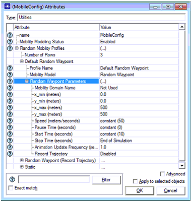
Mobile nodes are used in this simulation process and these nodes required some mobility profiles such that their key attributes like speed, destination, source and direction are defined at this level. To define the mobility profiles in general the mobility configuration object is used and edited to set the required setup for mobility. There are different mobility options available to the users and in this scenario a default random waypoint mobility model is used and the corresponding screen is as given below
Default random waypoint mobility model is used and the mobility model used here is random waypoint and the mobility modeling status is set to enable. Key aspects of the mobility like speed is set to a value of constant of 50 meters per sec, pause time is set to 0 seconds, start time is set to a constant value of 10 seconds and stop time is set to end of simulation. When all the attributes are set for the mobile configuration these profiles should be applied to all the mobile nodes and this can be set at the topology menu level. Set mobility profile is used for this purposed and with this all the mobile nodes are assigned with the default random waypoint mobility model and now they can move with the defined speed and pause time as described above.
Settings the DES statistics
DES statistics are used to estimate the performance of the network and they can be set across the OPNET simulation at three different levels like global level, node level and link level. In this simulation global level performance metrics are used and these metrics are set against the overall performance of the network. As voice is used as the application and low quality speech is used for the voice application the global level voice metrics and the wireless LAN level metrics are used to estimate the performance and quality of service level attributes are also set in this process and the procedure followed is given below
- Choose Individual DES statistics option is selected in the at the simulation network level by right clicking on the workspace of the simulation
- Global level attributes are set in this process and the related graphs are as shown below
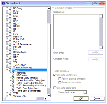
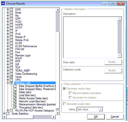
Choose Individual DES statistics option is chosen and then the corresponding screen is as shown below
Few Voice metrics are used across the performance evaluation and they are listed as below
- Jitter in seconds
- MOS value
- Packet delay variation
- Packet end to end delay in seconds
- Traffic received in bytes per seconds
- Traffic received in packets per seconds
- Traffic sent in bytes per second
- Traffic sent in packets per second
Above screen shows the wireless LAN parameters used and they are listed as below
- Delay in seconds
- Load in bits per second
- Medium access delay in seconds
- Network load in bits per seconds
- Retransmission attempts in packets
- Throughput in bits per seconds
Once all the attributes are set the required simulation run for 5 minutes to view the results and with this step the simulation of first scenario is done and the actual quality of service level voice applications used for the second and third scenario are as given below
Simulation procedure for scenario two
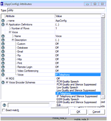
First scenario is duplicated from the scenarios menu and few changes are done to the voice application and they are shown in the below screen
Application configuration object is edited and the IP telephony is chosen as the required voice application and thus the quality of service aspects are changed to the IP telephony level voice application as shown in the above screen.
Simulation procedure for scenario three
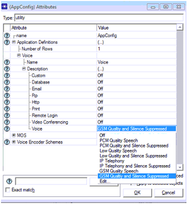
Second scenario is duplicated from the scenarios menu and the actual application used against the voice is shown in the below screen
GSM quality and silence suppressed voice application is used at the application configuration object and thus the quality of service is set to the GSM level as shown in the above screen. With this step all the three scenarios are created and next step is to run the simulation and the corresponding process is as shown below
Scenario management
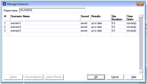
Once all the three scenarios are created and saved they can be run using the manage scenarios option from the scenarios menu and the corresponding screen is as shown below
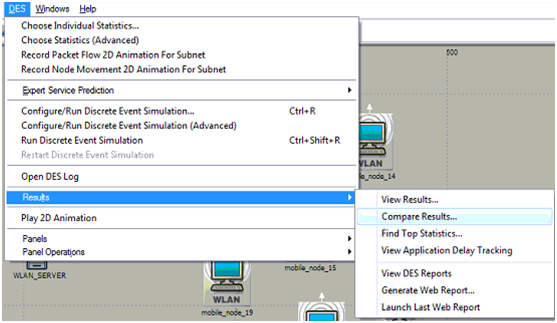
A table is opened at the user interface level and from this table it is clear that all the three scenarios are listed and the simulation duration is also set for 5 minutes and once the OK button is clicked all the three scenarios are run and then the next step is to view the comparison results and this can be done as shown below
Above screen shows the process to be implemented to compare the results and with this the comparison graphs can be viewed and they are shown in the next chapter.

