
This project has the three main modules
Application of Practical Shop Processing – Applicable Products
Lighting System of an Automobile – Demonstration Model
Parallel Clamp – Applicable Equipment
OBJECTIVE:
The main aim of the project is to have set up experience on demonstration of a lighting system for a Motor vehicle by studying the basic components of the lighting system and the operation of the lighting circuit.
USEFULNESS:
Traffic regulations require every Motor vehicle to be fitted with a correct lighting system. The lighting system is also important for an automobile to drive safely at day or night.
Unless lighting system has been used or insufficient components being applied, it will be very dangerous for the vehicle. By demonstration set of a lighting system for an automobile may support much more knowledge of this system to the students who study the concerning engineering subjects.
APPARATUS:
Types of lamps required are;
Main components
- Headlamps
- Tail lamps
- Side or Parking lamps
- Stop lamp
Accessories
- Warning lamps
- Fog lamps
- Panel lamps and
- Interior illumination lamps
Types of switch constituted in the lighting system are:
- Light switch
- Dip switch
- Stoplight switch
CONSTRUCTION: (WORKING PROCEDURE)
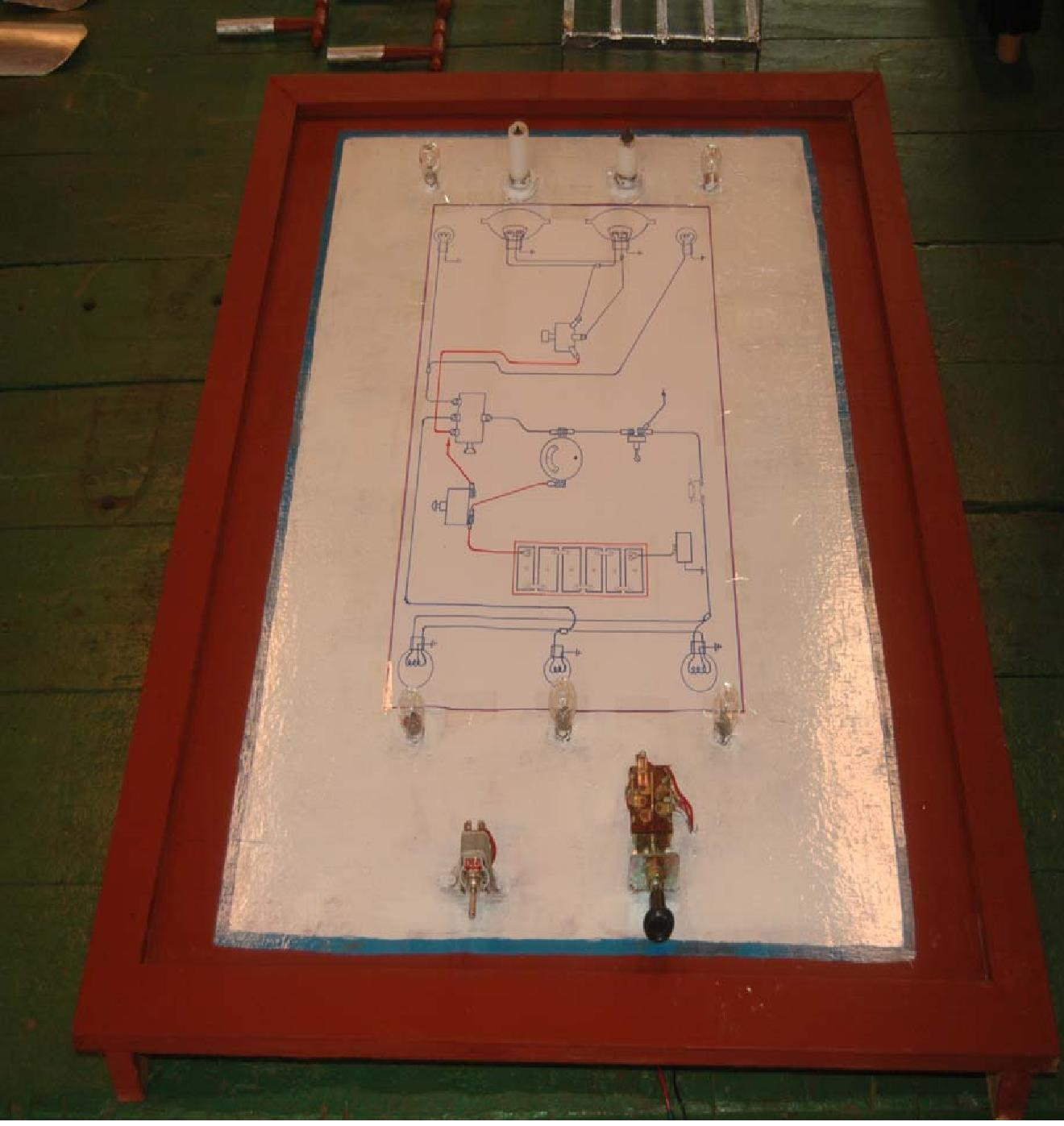
Panelboard is made of wood which has a length (3 ½ ′), wide (2 ½ ′) and thickness (¼″).
The circuit diagram is drawn on the panel board.
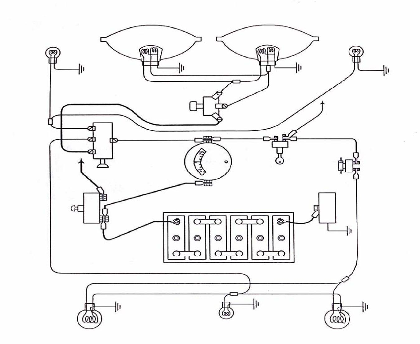
Complete Circuit Diagram
- The set of apparatus is set up according to circuit on panel board.
- The apparatus is connected to wire. After the setting has been established, the circuit is connected to the battery.
- And then, the lighting system for an automobile which display on the panel board can be started for its demonstration.
- Some of the other components are not display on the demonstration model board due to cost factor.
The following are the components’ specifications:
| Sr.No. | Components | No. Required | Specifications |
| 1 | Battery | 1 | 12V |
| 2 | Head lamps | 2 | 100 watt |
| 3 | Tail lamps | 2 | 5 watt |
| 4 | Parking lamps | 4 | 5 watt |
| 5 | Dip Switch | 1 |
CHOOSING CABLE SIZE
| CIRCUIT | CABLE SIZE | MAXIMUM CURRENT |
| SWG (size of wire gage) | CARRYING CAPACITY | |
| Battery and generator main feeds | 44/0.012
28/0.012 14/0.010 |
27.5 amps 17.5 amps6 amps |
| Other main feeds
Remaining circuits Starter circuits |
37/0.036
61/0.036 61/0.044 |
According to circuit length and vehicle operating conditions |
Firstly, it is calculated the current of headlamp and tail lamp. And the size of wire is selected from the table by comparing the result of current.
OPERATION:
THE LIGHTING CIRCUIT SYSTEM CONNECTION
- The battery is connected to the battery terminal of the light switch. The light switch is connected to the dip switch including full terminal and dip terminal connected to the head lamp’s each terminal respectively.
- Side terminal is connected to the side lamp or parking lamp.
- The tail terminal is connected to the tail lamp.
- The light switch control headlights, park sidelight, and tail lights.
- The dip switch enables the head light to be changed from dip to full beam, and vice versa, without affecting the park-light or the rear light.
- It should be noted that the stop lights will operate only when the ignition switch is on. Fuse is common practice to insert a fuse in the circuit of interior lights as on driving hazard is caused by the failure of the use in these circuits.
SWITCH OPERATION
- Naturally, during the right-driver, and in an emergency in the day-time, the full beam of the headlamp must be used and the number two-step of the light switches on. When faced with another vehicle, the dip beam is used so is not to dazzle the driver of that vehicle. Then the dip switch is used.
- When the number one step of the light switch is on, the parking lamps, the tail lamps and the number plate lamps all light up at the same time.
- As soon as the ignition switch is on, the brake lamps become operational and light up when the break is applied.
HEADLAMP ALIGNING AND FOCUSING
Headlamps must be correctly focused and aligned if the driver is to have good road illumination in the right place without dazzling another road user. They are the following.
- Front of vehicle to be square with screen.
- Vehicle to be loaded and standing on level ground.
- Recommended distance for setting at least 25 ft.
- For ease of setting one headlamp should be covered.
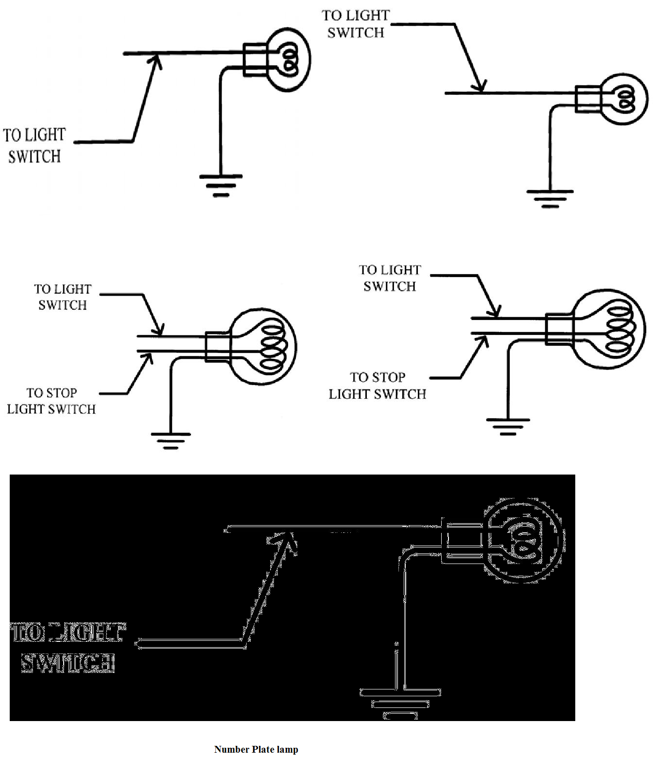
CIRCUIT CONNECTION DIAGRAM
Parking Lamp & Stop and Tail lamps & Number Plate lamp
PROJECT PHOTOGRAPHS
REFERENCES
1. J.A Dolan, AMSE, AMJED, 1996, Mortor Vehicle Technology and Practical Work Volume-1, lecture note in Mech. Eng: Dept., Ashton under Lyne College of Further Education Landon
2. R.E Owen, 1965, Electricity for Mortor Mechanics, Government Printer, Wellington, Newzeland.