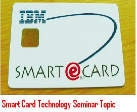
Smart Card Technology Seminar Topic

Smart-Card-Technology-Seminar-TopicSmart card technology seminar topic covers introduction of smart card technology, design of smart card, smart card application and usage, smart card examples, smart card applications and interfaces of smart card. Smart card is a ATM card sized plastic card with microchip integrated inside that card.

There are two types of cards available in the market one which stores information is called memory chip and card which can take input and make decisions with some memory is called a microprocessor chip. Because of decision making capability it is called active and smart card. This card has memory size of 32,000 bytes, in present market smart cards are built with math co-processors which can take perform encryption routing in less time and comes with memory space for storage.

This paper explains step by step procedure on how smart cards are manufactured. Smart cards are mostly used in banks for ATM cards, Credit cards, Visa cards and some of the other applications are pay phones, Mobile communication, banking and retail, electronic purse, health care and ID verification and access control. 

download Smart Card Technology Seminar Topic , paper presentation.

Mechanical Student Project on CNC Machines

Introduction:

CNC controllers are an intrinsic part of a machine or an industrial process. The project here “Mechanical Student Project on CNC Machines” explains about CNC machines. These CNC machines can be employed to produce machine tools as well as in the control mechanism. CNC controllers are capable of point-to-point control to complex algorithms for machine functions. CNC controllers can control axes from one-five and sometimes even six axes.

Some of the CNC machines are also built with integral displays, touch screen displays and keypads for programming and controlling. The programming language that is used for CNC machine devices is G-code and it can be loaded to the controller for the operation of the machine. To switch on spindle or other devices, M-code is the standard machine tool code employed.

CNC Machines Description:

Project on CNC machines explains about CNC controller whose main function is to perform binary coded commands. This control code designed for a machine has positioning (used for indicating position of work piece) and switching (controls servo components) information. These coded instructions are either entered manually at the control and at DNC.

Measuring system records the position of the work piece indicating the completion of the part program. Functions such s lubrication, coolant ON/OFF are activated via PLC through the relays and contactors at electrical panel. CNC machines possess several modes of operation. Machine precision can be greatly improved by features such as stored pitch error compensation. Another feature is helical interpolation that can make large diameter holes in work pieces.

Conclusion:

By using CNC controllers, there is a remarkable increase in the quality of products as well as it offers high flexibility. It increases the productivity and reduces the lead-time. The production is economical in nature and decreases the amount of scrap generated.

Download Mechanical Engineering Final Year Student Project on CNC Machines.

Control of Boiler Operation using PLC-SCADA Mechanical 2011 Project

Introduction to the Control of Boiler Operation using PLC-SCADA Mechanical 2011 Project:

In the industrial sector esp. power plants, the demand for high quality, efficiency and automated machines is increasing. Power plant units need to be closely monitored and supervised on a regular basis. In this Project “Control of Boiler Operation using PLC-SCADA Mechanical 2011 Project” the focus is on automating the boiler which is a crucial component of the power plant.

If we are going for automation it is also necessary to design a system that monitors the system and minimizes human errors. The system used her is SCADA-Supervisory Control and Data Acquisition which monitors and PLC (Programmable logic controller) that is used for internal instruction storage and implementation of functions such as sequencing, timing etc to control via digital I/O modules of various types of machine processes.

Description Of This Mechanical Project:

       PLC is used for achieving desired control through software programs. At the start of every cycle, the CPU the input signals from the module are stored in internal memory which is called PII. Once this PII (Process Input image) is read, the pointer of the CPU moves in the ladder program. The result of user program is stored in CPU and this is called as PIQ-Process output image. The CPU then transfers signal from PIQ to the output module and finally to the field control.

         The SCADA control system used in this system is used at the supervisory level. This may be done automatically or through operator commands. The data is obtained first by PLC’s scanning of all the field inputs that are connected to PLC. The data is scanned and processed to detect alarm conditions and if present it will display it on special alarm’s lists.

Conclusion:

          This Project Control of Boiler Operation using PLC – SCADA has tracked all the changes that have been taking continuously in the industrial sector. Stress is been given to automation of services that is happening all over the globe. In the future, further progress can be made in the purification and air circulation process.

Download Control of Boiler Operation using PLC-SCADA Mechanical 2011 Project.

Position Control of Manipulator Using PMAC with DC Servo Motors

The aim of this project is controlling the position of DC servomotor by DC servo drive and PC position controlling is for single or multi-axis.

Desired Position Command is given to the PMAC through PEWIN32PRO software to give output to Servo Drive to drive the servomotor at specific speed, direction and position.

The aims of the Position Control with DC Motors of Manipulator Using PMAC  Electrical Student project are integration of DC servomotor to clamp mechanism with DC servo drive, interfacing of Programmable Multi Axis Controller to the DC servo drives in closed loop, and parameter optimization and Tuning of the drive.

Youtube video link on Position Control with dc motor

When the system employ the PC based stand alone controller then the positioning of the table results possible with the soft CNC, motion control program, and PLC for I/O control of the system. The controller in this application is Programmable Multi Axis Controller (PMAC).

It is a controller with high performance servo motion which is capable of commanding up to 8 axes of motion with a high level of sophistication. Motorola’s DSP 56001 is the CPU for PMAC to handle all the calculations for 8 axes.

There are four hardware versions of PMAC. They are the PMAC-PC, the PMAC-Lite, the PMAC-VME, and the PMAC-STD. It  is  to  note  that  PMAC  is  a full  computer  and capable  of  standalone  operation  with  its  own  right and stored  programs.

The abbreviation of CNC is Computer(ized) Numerical(ly) Control(led) which implies computer control of machine tools for the purpose of (repeatedly).

Numerical control or numerically controlled (NC) machine tools are machines automatically operated by commands which are received by their processing units.

Advantages include Smaller outside dimensions and large torque, Good operating efficiency, Good controllability, and Cheap.

Conclusion:

This project is aimed to demonstrate the feasibility of integrating the DC servomotor to the clamping mechanism and controlling its position through Programmable Multi Axis Controller called PMAC with Dc servo drive.

Download Position Control of Manipulator Using PMAC with DC Servo Motors EEE Final Year Project Abstract with Documentation.

Powerline Voice And Data Communication For Device Operation

Powerline Voice And Data Communication For Device Operation offers an alternative means of communication. This project report provides an efficient means of communication over the existing electrical wiring as a communications medium. Power of communication, communicate using existing power lines. The main advantage of this type of communication is the existing infrastructure, which simplifies implementation General introduction to the power line communication, the understanding of some basic measurements of the properties to the behavior of the power line as a communication channel.

Every household would be connected at any time and services being provided at real-time. Using the power-line as a communication medium could also be a cost-effective way compared to other systems because it uses an existing infrastructure, wires exists to every household connected to the power-line network.

This system can be used in Nuclear Power Stations or Power Grid Stations, which are very hazardous for human beings to work in and needs heavy data transmission between the points. The present data signal transmission system can be further modified to send mixed signals such as graphics, video & audio signals over the power line. PLC technology is used to provide broad band internet over ordinary power lines. The system can be further modified to get the current status & execution of command of the load by audible beep. The above mentioned developments can be used in many public sector offices such as Railway enquiries, Bus Reservation Counter or in Electricity or Power Line Carrier Communication enquiry centers. Replacing the micro-controller with computer, one can make the system fully automatic and smarter one. The system can be more secured and comfortable with computer based control unit.

Powerline Voice And Data Communication For Device Operation Conclusion:

This report approach in designing a communication system for power line channel is a simple implementation of the receiver, thereby reducing the cost. A solid set of methods that are able to handle the unknown phase and attenuation. These methods are often combined with diversity coding (similar to Orthogonal Frequency Division Multiplex) to a communication system for power line channel, a flexible structure, the future must be updated, is recommended.

Download Power line Voice And Data Communication For Device Operation Electrical and Electronics Engineering EEE Final Year Project Report.

Fully Automated Burner Management System Using Plc

Fully Automated Burner Management System Using Plc The purpose of the protective relays and protective relaying systems is to operate the correct circuit breakers so as to disconnect only the faulty equipment from the system as quickly as possible thus minimizing the trouble and damage caused by faults when they do occur. Relays have revolutionized protection control metering and communication in power systems. Relay co-ordination will help to isolate the faulty region in the power system so that the fault at a particular region will not affect the other region in the system. Relay co-ordination can be done by selecting proper PSM and tsm of the relay and co-ordination can be checked graphically. Relay coordination in a power system will help to prevent the great loss and hazards caused due to the faulty conditions. Relays are also used to protect the transformer and motors also. Calibration of such relays are also done and also checked whether the relays are co-ordinate in each plant in FACT.

In a power system consisting of generators, transformers and distribution circuits, it is inevitable that sooner or later some failure will occur somewhere in the system. When a failure occurs on any part of the system, it must be quickly detected and disconnected from the system. There are two principle reasons for it. Firstly, if the fault is not cleared quickly, it may cause unnecessary interruption of service to the customers. Secondly, rapid disconnection of faulted apparatus limits the amount of damage to it and prevents the effects of fault from spreading into the system.

Conclusion:

The detection of a fault and disconnection of a faulty section or apparatus can be achieved by using fuses or relays in conjunction with circuit breakers. A fuse performs both detection and interruption functions automatically but its use is limited for the protection of low-voltage circuits only. For high voltages (say above 3.3kv), relays and circuit breakers are employed to serve the desired function of automatic protective gear. The relays detect the fault and supply information to the circuit breaker which performs the function of circuit interruption.

Download Fully Automated Burner Management System Using Plc Electrical and Electronics Engineering EEE Final Year Project Report.

Project Report On Uninterruptable Power Supply (UPS)

Project Report On Uninterruptable Power Supply (UPS) have become an indispensable element of many data processing installations (EDP), from desktop PC’s to mainframe computer systems. UPS systems provide a measure of insurance and security for the user who is concerned about data loss and hardware failures caused by power disturbances. The measure of insurance needed is proportional to the financial impact of the downtime caused by such an incident.

More recently, the introduction of computer based control systems in manufacturing and process control applications has prompted the need for UPS system in industrial facilities as well. Typical applications range from distributed PLC based controls to complete Distributed Control Systems (DCS) with power requirements ranging from 3 to 50 KVA. In addition to new plant construction, many older plants are upgrading both pneumatic and single loop control systems to distributed control, primarily to improve operating efficiency. Fundamental philosophical differences in system architecture indicate that industrial computer applications require different design parameters than their data processing counterparts and while UPS’s in commercial applications have largely become commodity items, industrial UPS systems remain an engineered product.

Project Report On Uninterruptable Power Supply (UPS) Conclusion:

In conclusion, there are many things to consider when specifying a UPS for industrial applications, only a few of which have been covered here. We’ve learned that industrial UPS systems generally have a high initial cost than their computer room counterparts. They are also more reliable and will be serviceable for the life of the plant. A cost justification based on the 15 to 20 year plant design life will show the cost of ownership for the industrial unit to be considerably lower. If you factor in the possibility of one incident traceable to the UPS that causes plant down time it becomes a foregone conclusion that spending a little more on the front end can save a substantial amount of money in the long run.

Download Project Report On Uninterruptable Power Supply (UPS).

Project Report On Computerisation Of Machine Lab

In this Project Report On Computerisation Of Machine Lab effort has been made to control and measure parameters such as voltage, current and speed of induction motor. Many of industrial processes and power generating plants are computerized so that to reduce labour cost, to obtain greater efficiency and improve quality. It is possible to obtain these requirements with use of advanced controlling technique such as Programmable Logic Controller (PLC).

Automation devices such as controllers and data systems and/or services. Systems and methods, to provide statements or other unit of data, the interaction of a programmable logic controller, which information or services of a suitable system for processing and to obtain optionally return a response set as a result. Furthermore, in accordance with one aspect of the invention, the native controller code, variables or tags attached to the stored data, processes or combinations of data and / or processes and automatically semi automatically. A or programmable logic controller (PLC) or programmable updated logic controller is a digital computer for the automation of electro-mechanical processes, such as rides such as control of machinery on factory assembly lines, or lamps. PLCs are used   in many industries and machinery. Different concerns than general-purpose, the present invention to facilitate communication between industrial computers, the PLC is designed for multiple inputs and output arrangements, extended temperature ranges, immunity to electrical interference and resistance to vibrations and shocks. Programs to control machine operation are typically stored in buffered or non-volatile memory. A PLC is an example of a real-time system since output results in response to input conditions within a limited time, otherwise unintended result of the operation must be made.

Project Report On Computerisation Of Machine Lab Conclusion:

A PAC provides in a single compact controller the advanced control features, network connectivity, device interoperability, and enterprise data integration capabilities found in PLC- or PC-based automation controllers. With these features, the PAC has become an integral part of meeting the new and diverse requirements demanded in a modern industrial application.

Download Project Report On Computerisation Of Machine Lab.