Packet Delay Variation in VOIP

Introduction to Packet Delay Variation in VOIP:

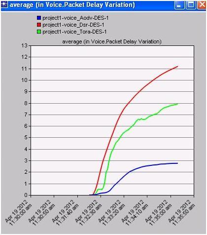
Packet delay variation indicates the overall difference in the packet arrival rate. In general the packet delay variation should be low enough for a better quality of service for the voice applications and the actual comparison graph is as shown below.

packet delay in voip

From the above graph it is clear that, the overall packet delay variation is less when the routing protocol is AODV. The average packet delay variation is more with the case of DSR routing protocol and this is due to the issue that DSR imposes more routing overhead across the peer nodes.

Even when the routing protocol is TORA the packet delay variation is more. Thus from the overall analysis it is clear that, when the routing protocol is AODV the overall packet delay variation is reduced and thus the quality of the voice application is enhanced. 

Packet End To End Delay in Voice

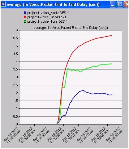
Packet end to end delay should be always less for a better quality of service. In general voice quality is enhanced when the end to end packet delay is reduced and the actual comparison graph is as shown below

packet end to end voice

It can be observed from the above graph that the overall packet end to end delay is more with the case of DSR routing protocol. In general the behavior of DSR will impose more packet delay overhead across the wireless LAN server. When the case with AODV routing protocol is considered the overall end to end packet delay is reduced and thus from the overall analysis it can be concluded that again AODV is the best routing protocol to enhance the quality of voice application. 

Thus when all the performance metrics are considered for voice application it can be observed that, the overall quality of the voice application can be enhanced when the routing protocol is AODV. The hybrid nature of the TORA routing protocol has affected few metrics of voice and the overall contribution is good. DSR is not suited for voice applications and the overall quality has reduced due to this routing protocol.


Seminar for Computer Science on Packet Delay Variation

Introduction to  Packet Delay Variation:

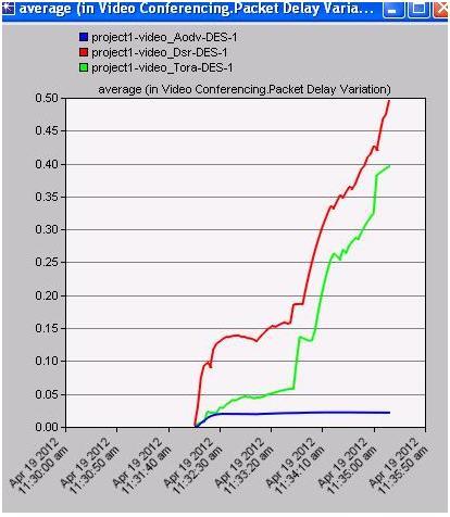
Packet delay variation indicates the overall delay imposed in the packet arrival times. This value should be less to improve the quality of the video applications. The actual comparison graph is as shown below.

packet delay

It can be observed from the above graph that the overall packet delay variation is more with the case of DSR routing protocol. As discussed in the previous section, the overall routing overhead on the wireless LAN video server will be more due to the routing nature of DSR routing protocol and thus the packet delay variation has increased.

It can also be observed that the packet delay variation is also more with TORA routing protocol and this is due to the complex routing process followed by the hybrid routing protocols. AODV is the best routing protocol that can be considered in this context and also the overall packet delay variation is low and constant.

This indicates that the quality of the video application can be enhanced if the routing protocol across the MANETs is AODV and thus always the reactive nature of the routing protocols will improve the performance of the video applications and also the required quality. 

Technical Seminar Ideas For CSE Packet End To End Delay In Video Conferencing

Introduction to  Packet End To End Delay In Video Conferencing  Technical Seminar Topic:

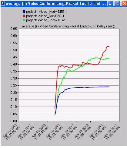
Packet end to end delay indicates the overall delay at the end to end communication process. This delay should be less enough to improve the quality of the video application and the actual comparison graph is as shown below.

packet end to end

It can be observed from the above graph that the overall end to end packet delay is less with AODV routing protocol. When the case with DSR and TORA are considered the end to end packet delay is very high and this is due to the internal routing behavior of the protocols and thus the quality of the video applications is reduced. The end to end packet delay is very less with AODV routing protocol and thus the quality of the video application can be enhanced in this case. 

From the overall analysis of the video results it is clear that, AODV routing protocol can be used across the MANETs to improve the quality of service across the video applications. When the case with DSR routing protocol is considered the overall packet delay variation and end to end packet delay is more and even it is same with the TORA. Thus AODV is always the best suited routing protocol for both the voice and video application quality of service for MANETS. 

Seminar on Mobile Ad hoc Network

Introduction to Seminar on Mobile Ad hoc Network:

With the increase in demand towards wireless networks there are many models introduced in this context. The key among them are MANETs (Mobile Adhoc Networks) and WSN (Wireless Sensor Networks) and the level of wireless operations are sophisticated across these networks. The range of application usage across the MANETs also has increased.

The main issue with the usage of applications across the MANETs is to provide the required levels of quality of service to the applications as the MANETS are infrastructure less networks. When it comes to the case of voice and video applications, the range of quality of service requirement is more and it is always important to provide the same across the wireless networks like MANETs. In general the voice and video application suffers with packet delays and streaming quality.

The main aim of this project is to improve the quality of service for the voice and video applications across the MANETs. In general the overall behaviour of any wireless networks mainly depends on the corresponding routing protocols and the key routing process implemented. The behavior of the applications and the corresponding quality of service requirements also depends on these routing protocols.

To improve the overall quality of the video and voice applications across MANETs, a total of 6 scenarios are created in this project. A MANET with 20 mobile nodes and a wireless LAN server is created in this project using OPNET Modeler tool. The actual simulation procedure followed in this context is explained in the previous chapters. Three scenarios are created for IP telephony voice application against three routing protocols like AODV, DSR and TORA and similar scenarios are created for video applications. The key performance metrics for voice application like Jitter, MOS, packet delay variation and packet end to end delay are used to evaluate the QoS requirements and for the video application the performance metrics like packet delay variation and packet end to end delay are used. All the six scenarios are run to achieve the results. From the overall analysis of the results it is clear that the quality of service of both the voice and video applications can be enhanced using the AODV routing protocol.

The reactive nature of this protocol is useful in providing the ample quality of service requirements for voice and video applications and thus implementing the AODV routing protocol will enhance the overall quality of the applications across the wireless networks like MANETs. 

CSE Minor Project Report on Computer Network

computer networks is nothing but collection of systems to gather interlinking with channel  and  to sharing of sources ,where at least exists one system is send/receive the data and another one responded to retrieve/send  the source  or otherwise interconnection of systems mutually sharing the information. To share the information between the system are maybe  get/use the resources  from one system to other system, to transmit the data ,mutual data transmission and also sharing Hardware devices like printer ,chatting, video  calls and mails are possible when system are in networking Environment.

The internet connection is possible while using the two types of technologies wired and wireless Technologies. Wired technology is existing by using the telecommunication link; where link is contain the cable wires (cables wires are twisted pair cable, coaxial cable, phone lines and an optical fibber). Wireless technology is exist using the various technologies are like satellite, radio-wave, Bluetooth, Wi-Fi and Terrestrial microware

 Network connection is possible by the usage of places there are three types Categories LAN, WAN and MAN.

LAN (local area network) is containing in single building where LAN size is restricted. LAN is depends on three different types characteristics .Those are size, topology and Transmission Technology, this run the speed between 10MBPSs to 100MBPS and now changed up to 10GBPS.Ethernet(IEEE 802.3) is mainly involved on LAN.WAN (wide area network) connection is existing abroad or a large geographical area like regional, country and continent. The speed starts from 10MBPS and up to 20GBPS.MAN (metropolitan area network) is establishing the connection on large campus or city.

 Download CSE Minor Project Report on Computer Network .

Technical CSE Seminar Topic on Bio Metric Systems

Collecting a data to identifying a person in manual way is time taking process, involves more risk for implementation and maintaining the data. In the present world data was easily misused by frauds. To secure a data from those people’s data should be maintained very confidential and access of data should be highly secure. For maintain the data in such manner we need highly protected system to maintained above things. For that Biometric system is very useful.

The Biometrics system is a device, by using this maintaining and implementation of the data in high secured manner. Using this data was not misused by any other persons.

Biometrics is an automatic mechanism used for the capture the real time persons finger prints and pictures. Biometric is containing the three type of identification, the mechanism is automated, storage process and interact with different applications.

Biometric system is contains two stages

Stage one: Enrolment stage

Stage two: identification stage

Enrolment stage contains scanning the data and the obtained data was stored

Identification stage contains cross checking the data with stored data, if it is matched system gives the permission for the proceedings

A sensor is scan for the physical density and creating digital presentation, there are two type of the topology to identifying the Biometrics physical and behaviour. The physical is depends on the identifying faces, finger prints, Hand and eye. Behaviour is taking the signature of the person and voice.

The limitation of the using the Biometrics only the user allow to perform an identity otherwise it should paly alarm alters.

Cost also increasing to scan for different human identifications. Voice is the least cost one.

Hand and IRIS are the highest cost one and give the good performance.

The Iris is a technology is used for to identify for the retina and eye colour.

The IRIS data is identifying the using the Rainbow. The Eye black one most powerful identities, this is the Technology used to identifying the person in ATM Canter and cash machines. While using the ATM canter pictures should be captures very easily when any illegal thing should be happened. The IRIS data should be unique.

 Download Technical CSE Seminar Topic on Bio Metric Systems .

E-Book Reader Project Class Diagram

Introduction to E-Book Reader Project :

E-book is also called electronic-book and it is look like form of a tablet pc, where e-book has more battery backup and easy to carry and possible for internet connection using Wi-Fi.

E-book reader  contains seven classes .Those are Register, home screen, registration form, user, Admin, Database, Guest and  book .Enter to the home screen must have login and id and password  otherwise enter the guest screen. If the user needs a membership to logon to use, he/she needs to fill the registration form where resister form contains name, user name, password, email-id and phone. After filling the form user enter the tools.

The tool is display the user information and user enquiries like which kind of books need to view, add, search, edit and navigation here the database is stored all the information required for  views and  user information and location to be stored. The book class contains the book name, author name, year of publishing, ISBN and numbers of books are in store. Where the guest class is contains the   display the books, search the book and Fill the register form. Where Admin class contained the all the operation of the editing like add user, delete users and add/delete books.

 When design part of e-book 2 type of classes used those are admin and book shelf. The admin class contains the Add/delete and search to books any users. Book shelf containing the operations like update, modification, add, delete by admin and user.

Download E-Book Reader Project Class Diagram .

Vehicle Monitoring and Control System Using Micro controller Project

Introduction to Vehicle Monitoring and Control System Using Micro controller Project:

We know that most of the accidents involve heavy vehicles such as trucks and busses. The main reason is because of them using huge engines and complex running structure compared to smaller cars there is greater risk of any of the system being failed while the vehicle is moving at a high speed or even because of driver error an accident may be caused.

Hence there is a need to monitor the vehicles parameters such as speed of the vehicle, temperature of engine, fuel availability, battery monitoring, proximity detection and coolant level is essential for the safety of vehicle. This information should not only be visible to driver but also to the base stations/owners.

In this system we make use of PSOC – programmable system on chip instead of microcontroller which reads all the parameters of the vehicle and transmits the same data to base stations using RF frequency.

PSOC’s has powerful processor architecture, advanced peripherals, Flexible on-chip memory, precision programmable clocking, programmable pin configuration, additional system resources and complete development tools.

Operation: – The important parameters of the vehicle are measured using appropriate sensors and this information is transferred to PSOC. Then the PSOC samples the data at regular intervals and the corresponding actions to be taken are stored in its memory for later or immediate action.

The speed of the engine is monitored every second and is converted into RPM which is displayed to driver continuously and when speed exceeds a certain value, the PSOC automatically activates a motor which apply the brakes. In this way the speed is limited to a predefined value.

Similarly all other parameters can be sensed and controlled immediately or at later stage at a base station. Hence this system of Vehicle-monitoring and control system using microcontroller helps in better management of heavy vehicles and reduces the accidents to highways to greater extent.

Download Vehicle Monitoring and Control System Using Micro controller Project report .

Vehicle Density Based Traffic Light Signaling System

Introduction to Vehicle Density Based Traffic Light Signaling System Project:

Traffic management is one subject on which every year millions of dollars are spent across the world to provide better traffic management. Especially in the developed countries such as India there is huge scope for a better traffic management.

Presently traffic is managed manually at smaller junctions and by using the signals lights (Red – Green – Yellow) at major junctions. This system will not serve for effective using of road space in major cities. The latest technology that can be employed is by using signal lights which function based on density of vehicles on the roads.

In this system all the timings of signal lights are fed to a computer basically termed as base station and through this station all the signals are sent to microcontrollers (89C51) placed on signal lights to operate accordingly. Sensors are connected to microcontrollers on every signal location which senses/reads the density of traffic in that particular road and sends the information to base station. Hence a bi-directional information flow system should be in place between signal lights and base station. Based on this information on density of traffic the signal light timings are automatically changed and also if needed traffic will be diverted to roads where traffic is less.

For sensing the traffic we can either use laser sensors or inductive type metal sensors. For transiting data we can use 433 Mhz carrier frequency. And use RS232 protocol for microcontroller (895C1) communication.

By deploying this model in real time we can save time being wasted in standing at signal, petro / fuel consumption can be reduced and make traffic management accurate.

Download Vehicle Density Based Traffic Light Signaling System .