MODIFIED DSR:
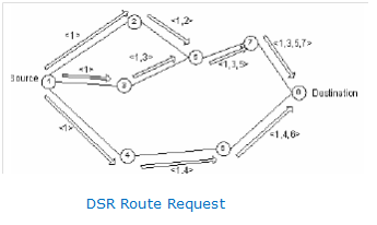
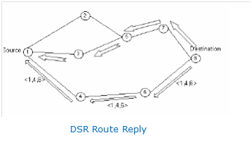
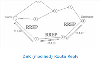
In DSR, the propagation of Route Reply as well as Route Request packets is represented in the following figures given below (Niranjan Kumar Ray, 2010).
Figure: DSR Route Request
Figure: DSR Route Reply
Figure: DSR (modified) Route Reply
In the protocol of DSR, the huge number of unwanted route replies is the major drawback, since a Route Reply is transmitted by each and every existing route leading to energy wastage i.e. battery power and unnecessary congestion. Therefore, it is suggested to restrict several Route Replies to only one Route Reply. This Route Reply is transmitted by the route where the initial Route Request is received by the destination, since it is defined to be the most active route for specific pair of source-destination during the moment of request transmission. Furthermore, this is the route where the packets of data can be quickly transmitted. Therefore, for transmission of data, similar one is selected as route, where the propagation delay is reduced to large extent by it. Moreover, it leads to increase in the delivery ratio of packets and reduction in control packets produced in the network. As a result, transmission of data is made optimum by these modifications. For the method of Route Reply, the modified DSR is represented in the above figure (C. Behrens, 2007).
Overhead is another disadvantage for protocol of DSR, which appears because of appending the intermediate node’s addresses that are being available on source to destination route. The available DSR protocol’s Data Packet Format is represented in the figure below.
|
SNA |
INA |
INA |
INA |
DNA |
DATA |
Figure: Data Packet Format of available DSR protocol
In the existing protocol, to decrease the overhead, the intermediate node’s addresses are suggested to be eliminated. Therefore, Data Packet’s header consists of only destination and source addresses as represented in the figure below (Mauro Marinoni, 2005).
|
SNA |
DNA |
DATA |
Figure: Data Packet Format of modified DSR protocol
As shown in the figure the following represents:
DNA– Destination Node Address
INA– Intermediate Node Address
SNA– Source Node Address
Previous Chapter -> Concepts of Energy Maps
Next Chapter -> Implementation of Overhead Reduction
Full Project Report -> Incorporating Energy maps to measure and compare the coherence time and spreading period across mobile wireless networks


