Network Load Balancing Project User Case Diagram

Each machine has its own copy of everything it needs to run the  Web application which includes the HTML files, any script pages (ASP, ASP.Net), any binary files (such as compiled .Net assemblies, COM objects or DLLs loaded from the Web app) and any support files such as configuration and local data files (if any).

This means each server must be configured separately and run the Web server as well as any Web server applications that are running. If you’re running a static site, all HTML files and images must be replicated across servers

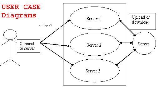
if any machine in the cluster goes down, NLB will re-balance the incoming requests to the still running servers in the cluster. The servers in the cluster need to be able to communicate with each other to exchange information about their current processor.

user case diagram network load balancing

Network Load Balancing Project ER Diagram

This processing as well as tine taken to generate well reports where also even when large amount of data was used. The system is designed in such a way that even when large amount of data used for processing there would less performance degradation.

Software Interface

The design part and interface id done the front end ASP.Net and SQL server as a backend of the project.

Operational requirements

The database or databases that are being failed over to the stand by server cannot be used for anything.

ER diagrams network load balancing

Network Load Balancing Project DFD Diagrams

It is concluded that the application works well and satisfy the needs. The application is tested very well and errors are properly debugged.  It also acts as the managements Systems to the valuable resources.

The issue date and returned date of books is updated at the database automatically at the time of enter by the Liberian. Additional checking whether the book is available in the library at that time is done by the system automatically; the backup is made automatically at the system startup. The speed of the transactions become more enough now.

dfd network load balancing


Network Load Balancing Project Module Description

Modules 

  1. Authentication Module.
  2. IP Address Representation Module.
  3. Load Servers Module.
  4. Load Balancing Module.
  5. Report Module 

Authentication Module: 

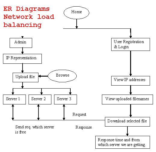
            The authentication module is to register the new users and previously registered users can enter into our project. The admin only can enter and do the uploading files into the servers. After login by every user and the admin the sql server checks the login id and password is valid or not. If the login is not valid it displays that the login is not correct. 

IP Address Representation Module: 

            The IP Address Representation module is to give the IP addresses which we are going to assign those as servers. We can enter and view IP addresses from this module. In load balancing system we can connect the three servers [system]. The connection has to be represented by the IP Address representation only. 

Load Servers Module: 

            The Load Servers module has the authentication for the administrator only can enter into this module. The administrator will do the encryption of the text file and store into the servers which we are assigned in IP representation module. This module will make the both public and private key for the cryptography. 

Load Balancing Module: 

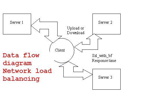
            The Load Balancing module has the authentication for users can enter into the upload page and can view the file name which the administrator stored into the servers. The user can select the file from the list and can download from the server which is in idle state. We will get the response time and from which server we are getting the file. Finally we can get the decrypted file from the key pair. 

Report Module: 

            We will get the response time and from which server we are getting the file. From the response time produce the chart report here. It compares the response time between the servers and download the given file in the better performance response time server. 

Sample Input and Output: 

            Input text file is given by admin and the encrypted format is stored in all servers. Output is decrypted file from the server which is in idle state. And it produce response time chart.

Network Load Balancing Final Year Project Source Code

The project “Network Load Balancing” is designed using Microsoft Visual Studio.Net 2008 as front end and Microsoft SQL Server 2005 as back end which works in .Net framework version 2.0. The coding language used is VB .Net. 

Many distributed real-time applications, such as audio- and video-conferencing, require the network to construct a multicast path (tree) from a sender to multiple receivers. Furthermore, real-time applications have Quality-of-Service (QoS) requirements (e.g. bandwidth). The objective of the routing protocol is to build a tree that is both feasible (i.e. satisfies the requested QoS) and least costly.

The cost of a tree depends on the costs of its links. The cost of a link should reflect the effect of allocating resources to the new connection on existing and future connections. Many studies have proposed multicast algorithms to construct low-cost QoS-constrained trees.

However, these studies assume that some cost is given for each link, and they do not examine the effect of the link cost function. In this paper, we examine the effect of various link cost functions on the performance of two classes of multicast routing algorithms under both uniform and skewed real-time workload.

We also investigate the impact of inaccurate network state information. Our simulation results show that when network state information is accurate (most up-to-date) at each router, the choice of the link cost function only has a negligible effect, if any, on the routing performance.

More interestingly, we find that, a link cost function that is more sensitive to load performs better when link state information is relatively accurate, while when link state information is more stale, a link cost function that is less sensitive to load performs better. This is more pronounced under higher load and when multicast groups are denser.

Network Monitoring System with Simple IP Subnet Calculator Database Design

TABLE AND DATABASE DESIGN

TABLE DESIGN

Admin Login Table

Database Design:

The database design is a must for any application developed especially more for the data store projects. Since the chatting method involves storing the message in the table and produced to the sender and receiver, proper handling of the table is a must.

In the project, login table is designed to be unique in accepting the username and the length of the username and password should be greater than zero

Network Monitoring System with Simple IP Subnet Calculator System Design

Design is multi-step process that focuses on data structure software architecture, procedural details, (algorithms etc.) and interface between modules. The design process also translates the requirements into the presentation of software that can be accessed for quality before coding begins.

Computer software design changes continuously as new methods; better analysis and broader understanding evolved. Software Design is at relatively early stage in its revolution.

Therefore, Software Design methodology lacks the depth, flexibility and quantitative nature that are normally associated with more classical engineering disciplines. However techniques for software designs do exist, criteria for design qualities are available and design notation can be applied.

OUTPUT DESIGN

In the project, if the employee has to communicate with other employees they can communicate through send and receive message.

INTERFACE DESIGN

The ODBC (Open Database Connectivity) interface is a pure .NET to execute SQL statement. The ODBC provides a set classes and interfaces that can be used by developers to write database applications. Basic ODBC interactions in its simplest form, can be broken down into four steps:

1. Open a connection to the database. 

2. Execute a SQL statement

3. Process the result

4. Close the connection to the database

Network Monitoring System with Simple IP Subnet Calculator Requirement Determination

Existing system

The existing system has been maintained manually. The system, which has been maintained manually, had been complex and complicated. There were many chances to loss the data and the work wouldn’t be an effective and efficient one. Manual operation is always been complicated to the organizations for maintaining the records. In the existing system

  • In this system we can’t monitor who all are accessing the files at the same time.
  • It’s difficult to find which are the files are updated and renamed.

Drawbacks of the existing system 

  • Maintenance of the system is very difficult.
  • Employee’s attentions are needed for maintaining the system.
  • There is a possibility for getting inaccurate results.
  • User friendliness is very less.
  • It consumes more time for processing the activities.

Proposed system

  • Considering the anomalies in the existing system computerization of the whole activity is being suggested after initial analysis by the organization.
  •  In this system we can monitor who all are accessing the files in the network at the same time.
  • When monitoring the connected systems, we can easily found what are the files updated and renamed.

ADVANTAGES OF THE PROPOSED SYSTEM

  • Fully Secured                                              
  • Role based access
  • Ease in maintenance                               
  • Notification about the modification 

Network Monitoring System with Simple IP Subnet Calculator Tool ER Diagrams

External Entities

External entities are outside the system but they either supply input data into the system or use the system output, they are entities which the designer has no control. Square or rectangle may represent external entities that supply data into a system or some times called sources. External entities that use the system data are sometimes called sinks.

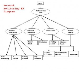
network moinitoring ER diagram

Network Monitoring System with Simple IP Subnet Calculator Tool Modules

Admin

            The Login module consists of username and password. This process is for authenisation.The  user name and password is correct it is link into next page. This process is done in login. 

 Network Monitoring System:

The most of the organization they connect more numbers of systems to form a network to make their work easier to share their files and folders. While connecting we want to monitor the network system activities for secure purpose. This Project deals with monitoring the Network Screen Activities. It has two methodologies one for Client and another for Server. In the proposed system we introduce current session option to monitor the network systems at the same time and in the accesses folder option shows the username and user accessed folders. While client logins to the server, the Client IP Address and System names are added to the server. Server will display all the user names, from server we can monitor the particular Client Screen Activities like that currently opened screens, what are all the files created, modified and deleted. 

 IP CALCULATOR SUBNET

 The calculator module certain process

  • Internet protocol
  • Network type
  • Calculate          

The calculate is used to calculate the network type and it class. The other process are prefix,net.mas,maximum number of host,network,broadcast,iprange,maximum number of subnets, wanted number of hosts. 

Internet protocol:

                The Internet protocol is used to know about the network type. The protocol is enter in the textbox and calculates. It will show the network type. If wrong protocol is entering in the textbox. It will show the error message.

Network type:

                The Network used to describes the class.

      • Class A:0:   127 255
      • Class B:128:191 255
      • ClassC:192:223 255
      • ClassD:224:239 255
      • ClassE:239:254 255          

Calculate:

                The Calculate is used to calculate the internet protocol and network type.In this system Maximum number of subnet is display.