ADOV Routing Protocol Implementation Design

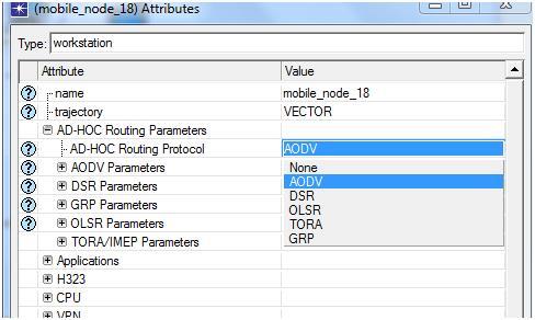
Similar simulation setup can be created for voice the applications and the routing protocol chosen in this context is AODV. Low resolution video is selected across the application configuration and the routing protocol used is AODV and the corresponding screenshot is as given below

adov routing 1

Routing protocol for video applications is selected as AODV and the corresponding screenshot is as shown below

adov routing 2

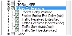
Now the performance metrics are chosen for video application and the corresponding screenshot is as given below

The following performance metrics can be used for evaluating the QoS of video application

  • Packet delay variation
  • Packet end to end delay
  • Traffic received bytes per sec
  • Traffic received packets per sec
  • Traffic sent bytes per sec
  • Traffic sent packets per sec

As with mobile nodes, similar performance metrics can be used for the rest of the scenarios in video applications as well. We only have to change the routing protocols to DSR and TORA.

Similarly run the results for evaluation against the simulation time after you create all required protocols.

DSR Protocol Simulation

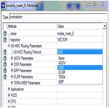
Simulation for DSR is similar to DES protocol but the routing protocol set for the mobile nodes and the server is alone changed. The steps to be followed in this protocol are as follows:

  • Choose all the mobile nodes and the server from the simulation environment
  • Select any one of the mobile node and edit it to the attributes level.

Go to the ad hoc routing protocols menu and change the routing protocol to DSR. Remember it was AODV with DES protocol. Refer the corresponding screenshot given 

From above screen it can be observed the AODV routing protocol is changed to DSR routing protocol.

Simulation of third scenario: TORA

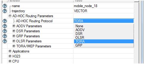
It is same as the second scenario only the routing protocol is changed to TORA throughout the process. Watch the screenshot below carefully.

This completes the simulation of all three protocols and the next step is to run the simulations against its simulation time. All the three scenarios are run for 15 minutes to achieve the results. 

Ad Hoc Network Project Reference for Setting Up The DES Metrics For Performance Evaluation

The main aim of this process is to analyse the packet losses in the network. The following steps are to be followed in setting up the DES metrics.

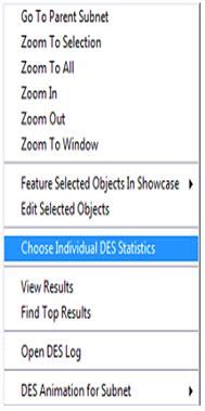
  • Right click on the simulation environment and chose the option  and Choose ‘Individual DES statistics’
  • A new window is opened where three options like global, link and node level are available. You got to choose the right option to evaluate the performance of the network
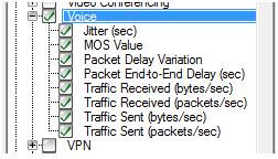
  • Refer  the following screenshot for Global level attributes, if chosen .

The following are the actual performance metrics used across the network against the traffic and packet sequences.

  • Jitter time in seconds
  • MOS Value
  • Packet Delay variation
  • Packet end to end delay in seconds
  • Traffic received in bytes per sec
  • Traffic received in packets per sec
  • Traffic sent in bytes per sec
  • Traffic sent in packets per sec

The same process stands good and can be applied for the second and the third scenario as well. The following are the actual simulation methodology implemented for the other scenarios. 

Setting the Mobile Definitions to the Nodes Ad hoc Project Reference

The main constraint of a mobile launch program is the packet losses across the network. This could be kept at a minimum by keeping the nodes used in the simulation pre set against few mobility patterns and these nodes can be added using the mobile configuration program. This mobility pattern is very important as if defines the destination, source and speed of the mobile nodes and the functioning of the mobile network on the whole.

The following points should be considered to set the mobility of the mobile nodes.

  • Right click on the object to edit mobile configuration object
  • Choose random mobility profile from the various options that prop out.
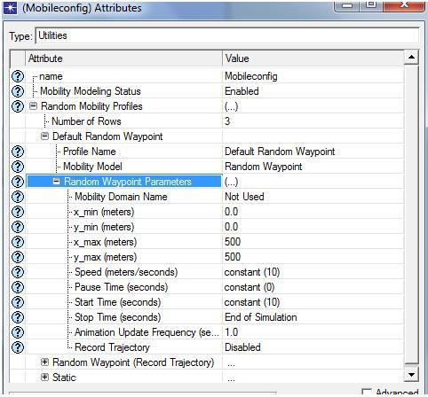
  • Expand the option, default random waypoint tab and set this as the required mobility model to the nodes. Check the corresponding screenshot given below for your reference.

From the above said process, random waypoint parameters are set and from the above screen it is clear that the speed of the mobile nodes is set to a constant value of 10, pause time is set to a constant value of 0 seconds and start time of the mobile nodes is repeated for every 10 seconds. Stop time of the simulation is set to bring about an end to the simulation as shown in the above screen.

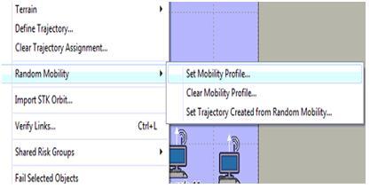
The edited mobility profile should be applied to all the mobile nodes and this can be achieved by choosing the option, ‘set mobility’ from the topology menu. Refer to the pictorial representation below to clear any of your doubts.

Once the mobility profile is set as shown above, all the mobile nodes should be assigned with this random waypoint mobility which helps the nodes to move randomly to process the traffic and to deliver the corresponding packets to the destination side. With this step the process of setting up the mobility patterns to the network nodes is done and the next step is to define the performance DES metrics. Its process is as follows. 

Node and Server Level Settings for Packet Analysis CSE Reference Material

In order to define the traffic as well as the packet analysis the node as well as the service level settings are needed which are against the nodes and then the overall configuration is been followed further in order to explain the server and node level settings. As discussed earlier, there are 20 different types of mobile nodes along with the single wireless LAN server and then the nodes which are been configured towards the traffic analysis as well as the packet analysis is situated in the initial step. The steps required to perform this activity are explained below:

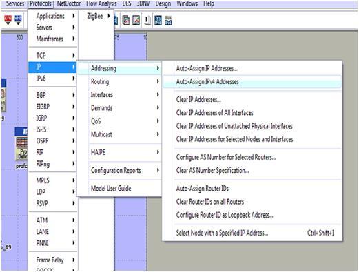
  • Select the appropriate mobile nodes as well as the WLAN server
  • Then after go towards the menu called protocol -à ApplicationsàIP
  • Then after starting from the IP section select the option called Auto assign and then the IPV4 address through which the actual nodes as well as the WLAN server which are allotted are been sent to the alternate !PV4 address and the screen shot which explains this process is shown below:
server 1

The auto assign IPV4 address which are been selected for the entire process are been allotted to the different mobile node along with the wireless LAN server as explained in the below screenshot. The next step is to configure the mobile nodes as well as the server which is added towards the routing protocols. It is explained in the earlier section that AODV is been used for the purpose of desired routing protocol the applicable mobile nodes along with the WLAN server is used and the steps are explained below:

  • The routing option is available to node levels or else to the server levels which are used to select the entire mobile nodes as well as wireless LAN server.
  • Within the entire available nodes, a single node is selected as well as opened within the edit mode which can be performed by clicking on right button
  • Within this edit mode the quality such as Adhoc routing protocols are used which allows the server to display the entire list of the routing protocols towards the users starting from AODV scenario and the process will be explained in the below screen
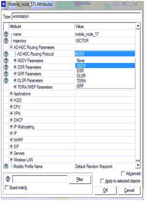
AODV is been chosen from the available list in which the total number of routing protocols which are seen in the screen can select al the nodes along with the server that are against the AODV protocol and it can be verified in the form of selected objects shown in the screen displayed above. In the entire process if the routing protocol is all set to serve the traffic against the patters of routing parameters the nodes as well as the server will be totally against the applications and profile definitions process is explained below. The total application level settings are situated towards the nodes that are explained below:

  • The total number of mobile nodes are been selected starting from the simulation networks and every node will be selected as well as edited in order to explain and define the total applications
  • Within the node level qualities there are different types of options available such as application destination preferences and then the tab which is expanded can be used to explain the application requirements
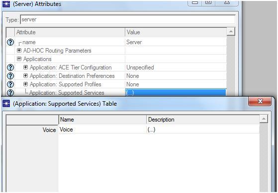
  • The total number of tows that are explained as single nodes requires support to the voice applications that are created with in the below screen
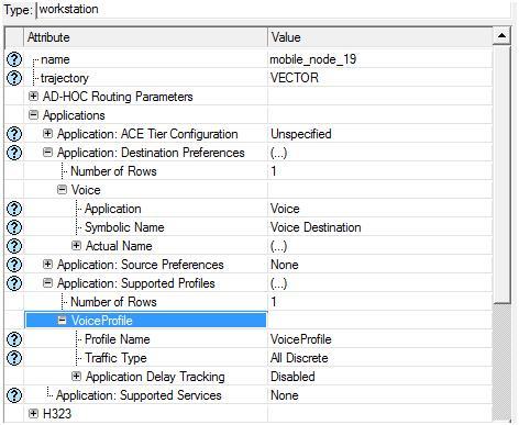
Application destination preferences is set to one rows and then the voice application is selected for this row and the symbolic server name is given as voice such that this server will generate the required voice traffic and the corresponding packets across the network.  Apart from the destination preferences now the application supported profiles are also set and in this context a single row is added to the section application supported profiles and voice profile is selected for this row as shown in the above screen. With this the node level application and profile definitions are applied to all the mobile nodes and the procedure followed to apply the same for wireless LAN server is given below

  • Select the wireless LAN server from the network and open it in the edit mode
  • There is an option like application supported profiles and expand this option to edit the profile settings for the wireless LAN server and the corresponding screen is as shown below

The above screen it can be identified that the voice profile which is been chosen as the main application facilitated and managed by the corresponding profiles the WLAN server will provide its support to the traffic that is distinct and then the voice profile will be generated and then the server will be capable of managing different types of the packets that are adjacent to the traffic. There is an alternate method which can be used to apply for the applications as well as the profile settings for the purpose of mobile nodes and wireless LAN server this particular process is known as deployment and these steps are explained in detail below:

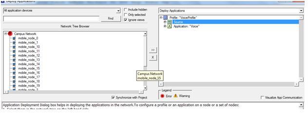
  • The user should go to the protocol menuàApplicationsàDeploy in order to define the applications
  • The new window is been displayed towards the user side and then the deployment process will be performed
  • The entire mobile nodes are been submitted towards the source and then the WLAN server is been submitted towards the destination side and the example is given below

From the above screen it can be identified that the entire mobile nodes are submitted towards the actual source. A success message like consistency check pass is displayed to the users if the deployment is done in a right manner. With this the corresponding email application and email profile are applied to the 20 mobile nodes and the single wireless LAN server. 

Profile Configuration Settings in Ad hoc Mobile Nodes

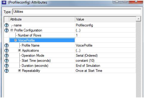
The further step in the simulation process is to define the profile configuration setting and there is a necessity of the profile definitions in order to perform the application requests that are obtained from the mobile nodes and then alternately the traffic is been produced which totally depends on the created profile definitions. The steps required to define the profile configuration settings are explained below.

  • In order to define and explain the profiles the profile configuration is used and then the profile configuration should be selected by using right click option
  • The different types of the rows are added to the profile definition and then the single row is been added to the context in order to support different types of voice applications that are already designed in the previous section
  • Only less number of definitions such as start time as well as end time are been set to the alternate network which is explained in the below screen.

profile configuration

From the above screen it can be noticed that the voice applications which are utilized in order to set the different voice profiles that are alternate towards the row are created for the purpose of explaining the profile definitions. 

Application Configuration Settings

In order to set the desired levels for the purpose of obtaining the traffic upon the networks the applications are needed. Depending on the type of application selected and used the traffic sending process as well as traffic receiving process are performed. Within the OPNT modeler process different types of applications are been used and then the voice application is been designed and the below steps are required to perform this action.

  • The user should give a right click on the application definitions towards the object in order to edit the different attributes that are required
  • There is a separate tab called application definition within this section and then the user can add the number of rows required in which each and every node will represent a single application
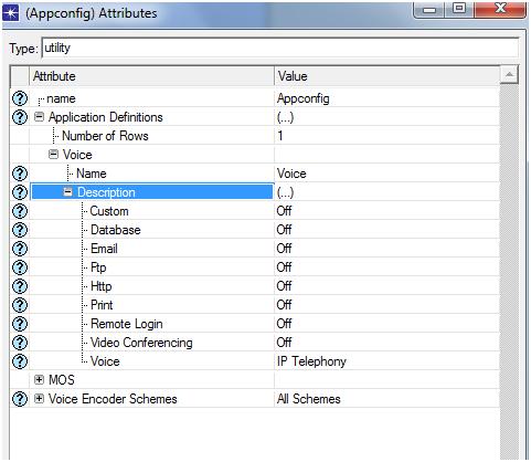
  • But within this simulation only single and unique application is utilize and for this reason only single row is created within this process
  • The application voice is created in which each and every voice based application is selected
  • The IP telephony is been selected for the purpose of application and then the next screenshot obtained is given below

application configuration settings

The IP telephony application is been used within this particular scenario in which the voice traffic is been produced upon the networks and then once if the application is selected then click on the OK button in order to apply these settings. The application definitions which are needed are been produced in this step and then in order to create the profile definition the further process is explained below.

Simulation Steps Involved in Using ADOV Protocol

Within this first scenario the ADOV protocol is been utilized along with the 20 mobile nodes in order to produce the traffic. The different types of voice applications are used within this scenario in order to identify the service requirements of the quality by using this protocol. The different steps are followed in order to perform this scenario such as follows:

Steps to form basic network

The MANET- mobile Adhoc networks is widely used within this project in order to estimate the entire performance of the AODV protocol which is totally against the different packet losses which needs some important steps to be followed to create the network which is general. A single LAN along with 20 different types of mobile nodes are utilized within the simulation process in order to set the traffic upon the networks. The steps that are to be followed to create the network are explained below:

  • Initially the user should open the OPNET modeller simulation tolls and then the user should select the option to open new file in order to start the simulation process
  • The project name as well as scenario names should be created in order to obtain the new scenario
  • By selecting a specific option users can create the scenario which is employ in which the OPNET modeler can be utilized to load the different types of default scenarios that are totally inherent into the networks.
  • In order to select specific type of topology various options have taken place and then alternately in the simulation process the simple campus network is been selected to perform the topology functions
  • In the next step the campus size should be situated and then the simulation size of the campus should be set with size of 1000X1000 square meters
  • There is a necessity of new network model family for the purpose of simulation of MANET and within the entire available models the appropriate model is selected in order to perform the simulation process. By following the above mentioned steps the basic network which is required to perform the simulation process is explained and then the different objects which are considered from object palette will be utilized in the simulation process in order to get the expected results.
  • Depending on the requirement of mobile nodes 20 different types of wireless LAN mobile workstations are utilized which performs an activity as the main source in order to get the final traffic in which the actual real packet analysis process is performed
  • The single WLAN server is utilized which acts as an individual application destination along with a server as well as the 20 mobile nodes.
  • As discussed earlier the actual aim of this project is to evaluate and estimate the different packet losses towards the Mobile Adhoc networks which requires a traffic and source applications to perform the actions. The configuration is required to the applications in order to produce the traffic that is needed to analyze the entire data packet losses
  • The profile definition is been created for the purpose of application which is performed by making use of the profile configuration nodes which are gathered from the object palette.
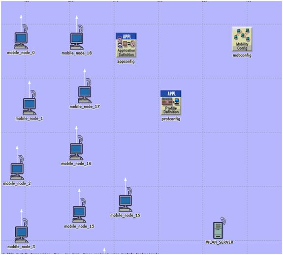
  • The major and important step within the entire simulation process is to set the mobility towards the nodes by making use of the mobile configuration object which is there to perform the process with the object palette and then the finally by following all these steps the first scenario is obtained which is explained in the form of screen shot.

simulation steps

From the above proposed screen it can be identified that the total number of 20mobile nodes starting from mobile_node_0 to mobile_node_19 is been created with the individual WLAN server with different traffic definitions.

In order to set the definitions different types of configurations such as application configuration, mobile configurations as well as the profile configuration are used. The application configuration settings are explained in the further steps.

ECE Seminar Report on Voice Morphing

Introduction to Voice Morphing Seminar Topic:

Imagine if your voice can be changed just like the president and give instructions to get your visa stamped. It looks as if kidding but technology can make it possible using Voice Morphing. Turning of one speech signal into another speech signal is called as Voice morphing.

Voice morphing technology is first developed at Los Alamos National Laboratory, USA by George Papcun and had seen light in 1999. Voice morphing is a process of cloning speech patterns and bringing accurate copy of a person’s voice using which an operator can say anything in the voice of someone else.

Voice morphing main aim is to keep intact the shared characteristics of starting and ending signals in the process of making a smooth transition while changing other properties.

Speech morphing can be successfully achieved by signal transition represented by acoustic waveform taken from sampling of analog signal. This signal is split into multiple waveforms or frames. In this way transformation can be applied to each frame of signal. Two important properties of signal to be known are pitch and overall envelop of sound. Manipulation of pitch plays important role in morphing. In order to successfully morph pitch should be smoothly changed throughout the signal.

To achieve this signals are stretched and compressed to match important sections of each signal. In order to create intermediate sounds for morphing interpolation of two sounds can be done. finally the frames are converted back into a normal waveform.

Voice morphing has military applications such as psychological warfare of subversion. It can be turned into powerful weapon in provide fake orders to the enemy’s troops as if coming from their superiors.

Download ECE Seminar Report on Voice Morphing.  

Technical Paper Presentation on Virtual Retina Display

Introduction to Virtual Retina Display Presentation:

Virtual Retina Display (VRD) is an alternative to conventional bulky power consuming video display units. In VRD’s video is focused on minuscule image right on retina. Color is produced using LED triads of Red, Green, and Blue (RGB) by mixing in required proportion. Video signal is intensity modulated when light gets scanned by retina. Collimating optics is used in raster patterns when scanning is performed directly by retina.

We can use VRD systems in military applications for helmet mounted displays. In medical field it can be used for complex operations. It can also be used in cameras for better display screen which consumes less power that the conventional liquid crystal on silicon and organic LED displays.

Key features of VRD are as follows:

Weight to Size ration: – since there is absence of intermediate screen and all parts being small and light weight VRD is portable and can be used in hand held and head mounted devices.

Power consumption: – VRD consumes power in mille watts since scanner is a resonate device with high figure of merit. Entire light enters pupil in VRD because of employing small aperture. This allows power efficiency.

Resolution and brightness: – With a million pixels and high grade scanners are having an ability to scan over 1000 lines per frame almost nearing HDTV. Even in day light SLD source provide brightness to the level of see through mode.

Stereoscopic display: – in order to provide natural vision both eyes are addressed separately using stereoscopic display. 

Download Technical Paper Presentation on Virtual Retina Display.