Securing Aggregate Queries for DNA Databases Project

Concept:

Efficient scheme which ensures that plaintext data cannot be recovered as long as the adversary has access to at most all but two ciphertext blocks, even when the encryption key is exposed.

Owner:

  • Owner has to register to get login.
  • File Upload: owner can upload the file to cloud . this file will be visible to cloud-A who will generate private key.
  • View Files: owner can view the uploaded files.
  • Upload to Cloud: owner can upload the files into cloud with a valid privatekey which is generated by cloud A file will be split into two parts and will be stored in two diiferent accounts in Drive-Hq cloud.

User:

  • User has to register to get login.
  • View files and send request: user can view the cloud files and he can send request to cloud
  • Verify keys and download: To download total file User need to verify splited part-0 file from cloud-a with 1st key which is sent to user mail by cloud-a and veirfy part-1 splited fle from cloub-b with 2nd key which is sent to user mail by cloud-b.
  • If both key are matched then only user can download if not he is malicious user.

Cloud A:

  • Cloud has to login
  • View Files: cloud A can view the files which are uploaded by user and cloud can provide private key for respective files
  • Split files: cloud A can view part of splited files which are uploaded by owners.

Cloud B:

  • View user request: cloud-b can view user requests and can give public keys to requested user to download files.
  • Split files: cloud A can view split files

Attacker module:

  • Attacker will search for keys and download part from cloud-a but he cant view that data because he can get only partial part-0 of file. Attacker dont know how to get part-1 and where it was stored.
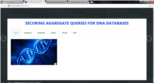
Home page

The above screenshot shows the home page. The header tab includes hospital 1, hospital 2, cloud 1, cloud 2 and the user modules are shown here.

User registration page
The above screenshot shows the user registration page. A new user can register here by filling up their Name, email address, password, and Date of Birth and Contact details.
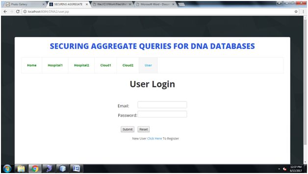
User login page
The above screenshot shows the user’s login page. An already existing user can login with the user name Password, If not he/ she can register newly.
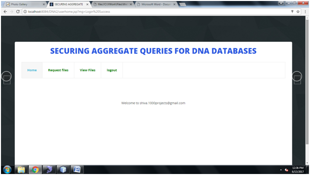
User main page
The above user main page shows the user’s main page after he logs into his account.
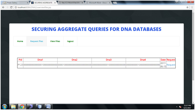
User file request page

The above page shows the user’s file request page. Here cloud will check and respond to the user’s requests of the file.

User file view page

In the user’s file view page, the files that have been uploaded by the Hospitals modules are displayed.
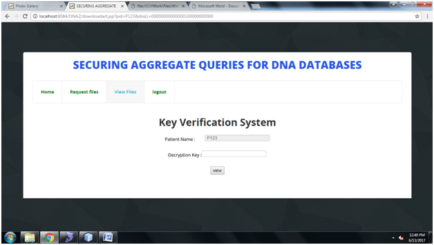
Key Verification Page

In the key verification page, the researcher verifies the decrypted key with the patient name.The Decryption key Is received To registered mail Id.

Display patient information page

In the display verification page, if the decryption key matches, then only the researcher able to view the patient details.
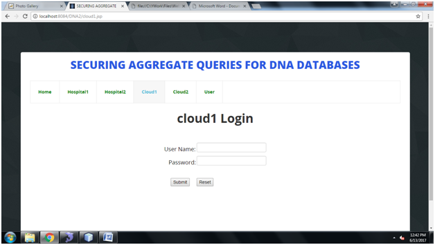
Cloud 1 login page

In the cloud 1 login page, To get Access to cloud home page must enter the valid username and password.
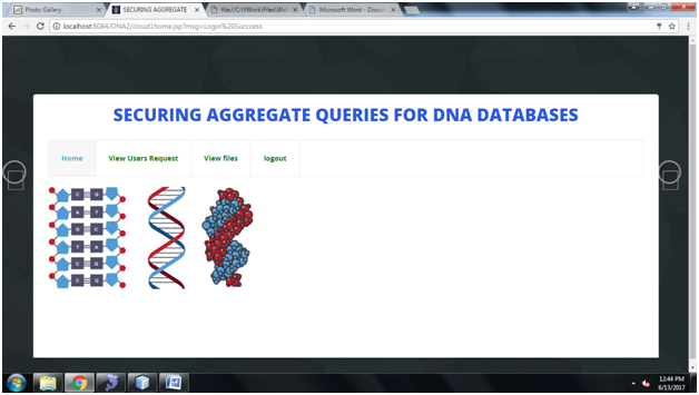
Cloud 1 home page

In the cloud 1 home page, this page shows the functionalities of cloud 1.
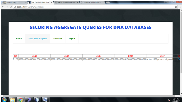
View users request page

In the user’s request page, the cloud can view the requests send by users and he can respond and send key to user’s mail.
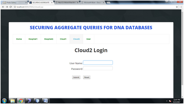
Cloud 2 login page

In the cloud 2 login page, To get Access to cloud home page must enter the valid username and password.
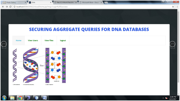
Cloud 2 main page

In the cloud 2 main page , this page shows the functionalities of cloud 2.
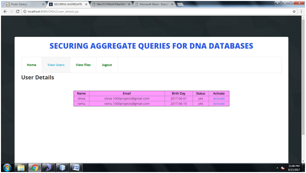
Cloud 2 users view page

In the cloud 2 users view page, cloud can view Researcher who are registered and Cloud can activate the Researchers.
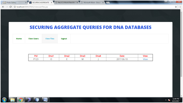
Cloud 2 view files page

In the cloud 2 view files page, cloud can view the files which are uploaded by Hospital and cloud can provide private key for respective files.
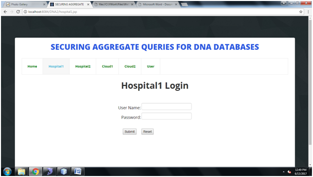
Hospital 1 login page

The hospital 1 login page is the official login page for the hospital, to get Access to hospital home page must enter the valid username and password.

Hospital 1 main page
In the hospital 1 main page , this page shows the functionalities of hospital 1.
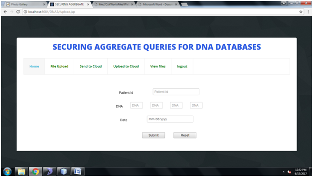
Hospital 1 file upload page
In Hospital file upload page, Hospital can upload the patient information to cloud.

Hospital 1 send to cloud page
In the Hospital 1 send to cloud page, Hospital can view the uploaded files and can Send files to cloud2 for private key.

Hospital 1 view files page
In the Hospital 1 view files page, Hospital can upload the files into cloud with a valid private key which is generated by cloud 2.
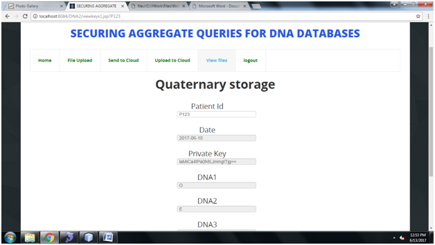
View files Quaternary storage page
In the view files page, The private key generated and uploaded to real time cloud(Drive HQ).

UML Diagrams:

Class Diagram:
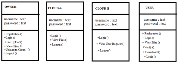
Use Case Diagram:

Sequence Diagram:

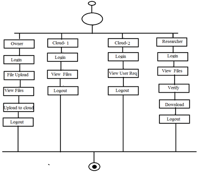
Activity Diagram:
Download the Securing Aggregate Queries for DNA Databases Java Project Code, Database, Project Report
Airline Catering Services .Net Project

Purpose

India has a major market where there is a strong demand for top quality in flight catering services. A complicated system like airline catering needs to consider various issues. It is the independent international system which provides a collaboration work made easy by chef and administrator.

Project Scope

Airline Catering Services software provides a better user interface in the catering system. Here we maintain all the details of the chef and we maintain the all the goods available in the store. This makes the chef work more reliable. Apart from this Airline Catering Services application we also maintain transport details we have different vehicles to carry different food materials.
Communication interfaces:

System Design:

Study of Existing system

“India is a major market where there is a strong demand for top quality in-flight catering services”. A complicated system like airline catering needs to consider various issues. Till now this type of system is not yet integrated to provide automated catering services.

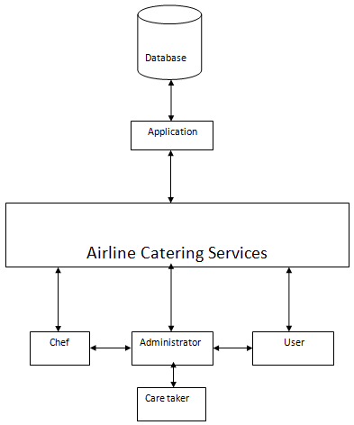
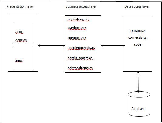
Technical architecture:

Proposed system

Airline catering services is the independent international airline caterer services which provides a collaboration work made easy by chef and administrator. Transport and Retrieval System have been devised manually, making the entire material handling/stacking process completely mechanized.
Using this Airline Catering Services application administrator can get the details such as number of passengers traveling in the aircraft, the items to be packed for the airlines, what type of food Items (veg or non-veg), beverages that are to be supplied. He can send the required information for administrator.

UML Diagrams:

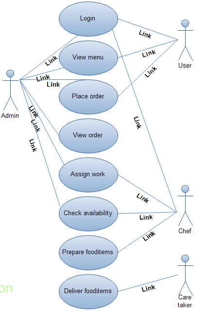
Use Case Diagram:

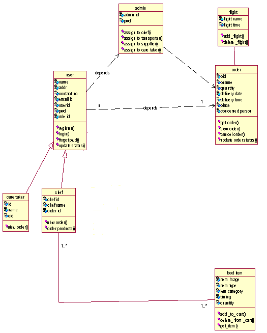
Class Diagram:

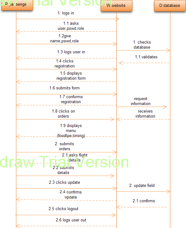
Sequence Diagram for User:

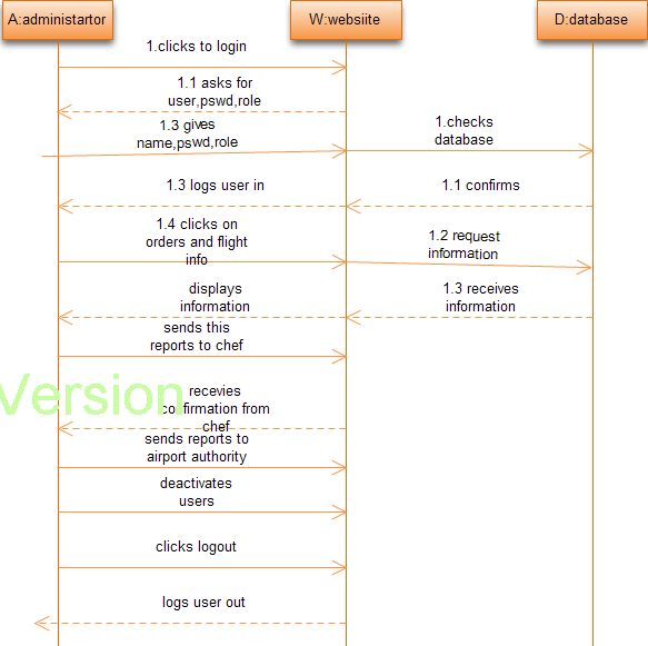
Sequence Diagram for Admin:

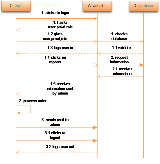
Sequence Diagram for Chef:

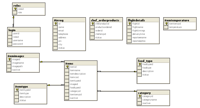
Database design:

Requirements

Functional requirements

The following modules are present in this Airline Catering Services application:

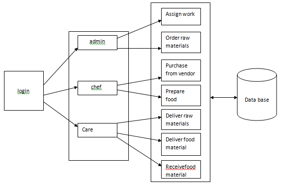
  • Administration System: In this module admin can send all the details required to other members. Details like number of passengers travelling in the aircraft, the items to be packed for the airlines, what type of food items (veg or non-veg), beverages that are to be supplied will be configured.
  • Chef: The chef should have the details like number of dishes to be prepared. He will plan what are the items and beverages to be purchased from the vendor. He has to take care of each and every goods that is required for the chef, and he has to maintain each and every flight timings and what the food to be served for that particular airline he has to maintain all that details
  • Care taker: He is responsible to transfer the goods from the transporter to airlines. He plays a major role, he has to maintain all the records of what all the goods he delivered and at what time he received the good. He has check whether the food is good or spoiled during the traveling.

Database tables

TABLE NAME:  Airreg

Column name Data type Length Allow null
Id int 4 0
name varchar 50 0
email varchar 50 1


telephone varchar 50 1


address varchar 150 1


pin varchar 50 1


city varchar 50 1
status char 10 0

TABLE NAME:  Chef_Orderproducts

Column name Data type Length Allow null
chefProductsId int 4 0
ProductsOrdered varchar 2000 1
OrderId int 4 1
ChefEmpId int 4 1

TABLE NAME:  roles

Column name Data type Length Allow null
role_Id Int 4 0
role varchar 50 0

TABLE NAME:  Flightdetails

Column name Data type Length Allow null
FlightId int 4 0
FlightName varchar 50 1
FlightTimings varchar 50 1
Deliverytime varchar 50 1
Reporteename varchar 50 1
Reporteephno varchar 50 1


TABLE NAME
:  Food_Type

Column name Data type Length Allow null
foodTypeId int 4 0
foodType varchar 50 1
description varchar 150 1
status bit 1 1

TABLE NAME:  ItemImages

Column name Data type Length Allow null
imageId int 4 0
imageName varchar 50 1
imagePath varchar 50 1
IsActive bit 1 1

TABLE NAME:  Items

Column name Data type Length Allow null
ItemId int 4 0
itemName varchar 50 0
itemDescription varchar 150 1
itemCost float 8 1
ItemTypeId int 4 0
imageId int 4 1
foodTypeId int 4 1
categoryId int 4 1
ItemTempId varchar 50 1
IsActive bit 1 0

TABLE NAME:  Item temperature

Column name Data type Length Allow null
ItemTempId int 4 0
Temperature varchar 50 1

TABLE NAME:  Itemtype

Column name Data type Length Allow null
ItemTypeId int 4 0
ItemType varchar 50 1
description varchar 150 1
status bit 1 1

 Software :

  • Language : Microsoft C#
  • Microsoft ASNet
  • Runtime : Microsoft Framework
  • Environment : Microsoft Visual Studio IDE
  • Web server: Internet Information Services (IIS)
  • Database : Microsoft SQL Server
  • Operating system : Microsoft Windows

6.2 Test cases:

Test case number #01
Module Airline
Description Registration
Input Provide the details in the registration page for the airlines
Expected Output Request for username and password to be entered
Actual output Request for username and password to be entered
Test case number #02
Module Airline
Description registration
Input Provide the login details
Expected Output Displays a message that registration is successful
Actual output Displays a message that registration is successful
Test case number #03
Module Airline
Description login
Input Provide the login details and select the user option in dropdown
Expected Output Displays catering services home page
Actual output Displays catering services home page
Test case number #04
Module Airline
Description Home page
Input Click on about us link
Expected Output Displays the catering management information
Actual output Displays the catering management information
Test case number #05
Module Airline
Description Home page
Input Click on contact us
Expected Output Displays the address of catering services
Actual output Displays the address of catering services
Test case number #06
Module Airline
Description Place an order page
Input Select the food timings and food type
Expected Output Displays the item name, image, description and quantity information
Actual output Displays the item name, image, description and quantity information
Test case number #07
Module Admin
Description Home page
Input Click on orders link
Expected Output Displays the flight details, order details and delivery time
Actual output Displays the flight details, order details and delivery time
Test case number #08
Module Admin
Description Home page
Input Click on orders and view
Expected Output Displays the order details previously entered and  the items ordered
Actual output Displays the order details previously entered and  the items ordered
Test case number #09
Module Admin
Description Home page
Input Click on orders and accept
Expected Output Request to select the chef to whom order has to be assigned
Actual output Request to select the chef to whom order has to be assigned
Test case number #10
Module Admin
Description Home page
Input Select the chef from the drop down list
Expected Output Displays the particular chef information
Actual output Displays the particular chef information
Test case number #11
Module Admin
Description Home page
Input Click on submit
Expected Output Displays a message that the order has assigned successfully
Actual output Displays a message that the order has assigned successfully
Test case number #12
Module Chef
Description View order
Input Click on order link
Expected Output Displays the order item details and order status
Actual output Displays the order item details and order status
Test case number #13
Module Admin
Description view status
Input Click on order status
Expected Output Displays status as product ordered by chef
Actual output Displays status as product ordered by chef
Test case number #14
Module Chef
Description if the order is ready
Input Click on chef inprocess order link
Expected Output Click on completed preparing food link
Actual output Click on completed preparing food link

Output Screens shots

  1. Login
  2. “User” home page
  3. Select Food as per our choice
  4. Place Order
  5. Admin Login
  6. “ADMIN” check for orders with respective of flight details , food types. He sends order information to “CHEF”
  7. CHEF logins and check his orders and prepares food .

Conclusion:

This  proposed  project  “Airline Catering services” is  analyzed ,designed , developed and  tested in the specified  period  of time  using the Advanced Microsoft  .Net technology   to automate the general operations held in a catering system

Track Machine Management for Railways .Net Project

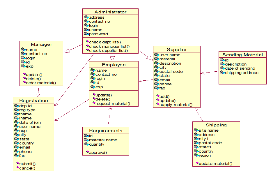
Railways is a big organization which need to maintain the details of different things like tracks and their material so it is tedious job to maintain all these details manually,in order to overcome this problem track procurement management system is providing the successful tools and techniques to a broad range of activities like maintaining  inventory of the material needed for tracks like bolts,nuts,joints etc…,the project mainly contains the modules like material purchasing,material issuing, stock maintenance, zonal issuing,monitoring of track machines.

This project is about the maintenance of Railway tracks of particular region.

UML Diagrams:

Class Diagram:

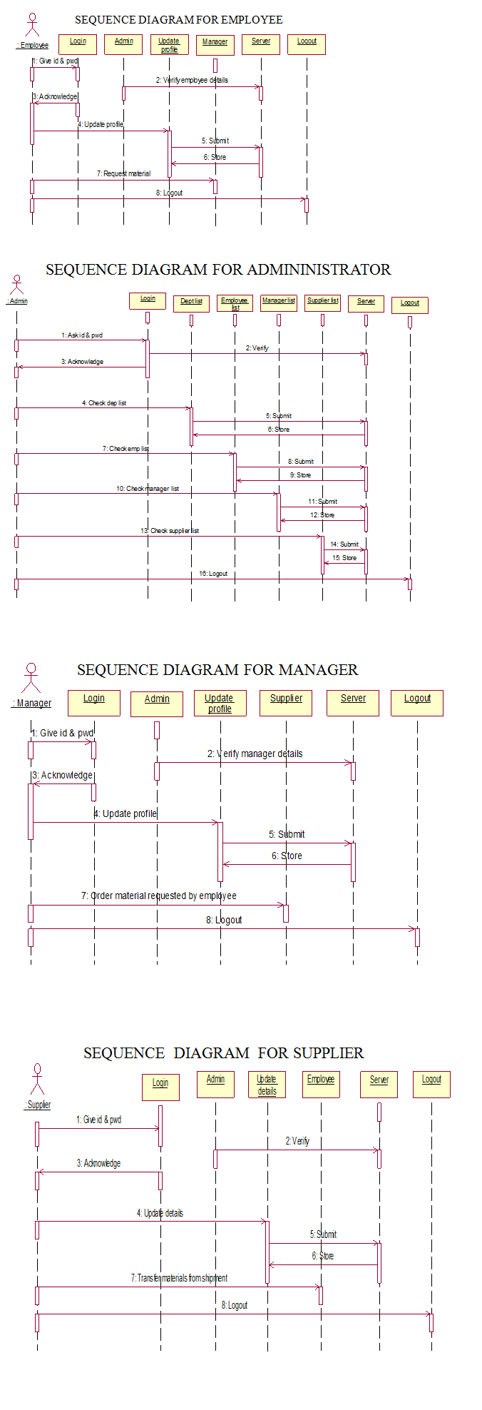
Sequence Diagram for Employee, Administrator, Manager & Supplier:

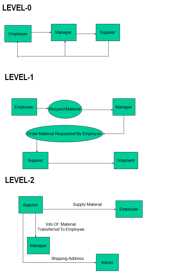
Data Flow Diagrams:

And this project consists of four modules.

  1. Admin
  2. Manager
  3. Employee
  4. Supplier

Administrator

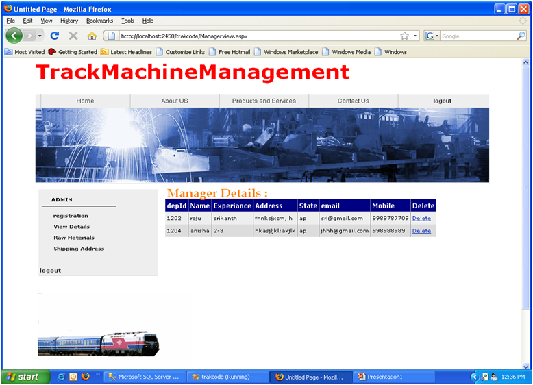
  • Views the details of manager,employee, Supplier.
  • Updates,deletes details.
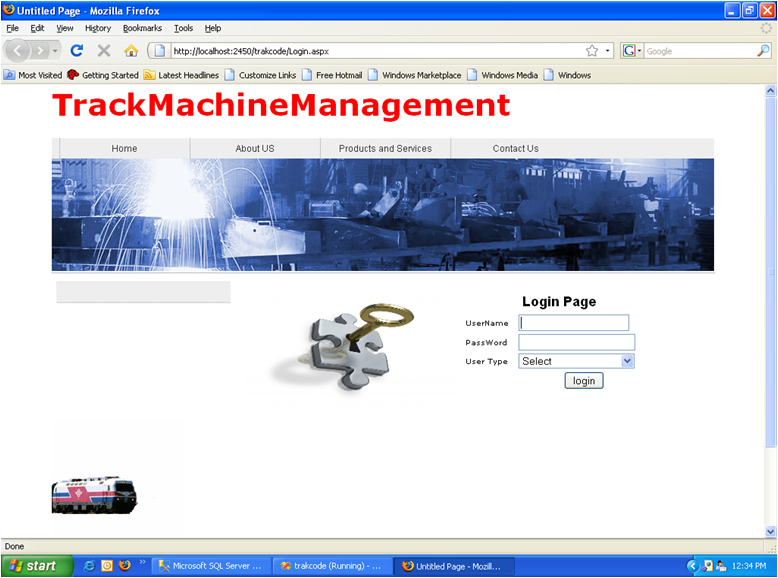
  • To view the details ,admin should login

  • Admin logins by using user name –admin
  • User type admin
  • Views the details of manager,employee and supplier.
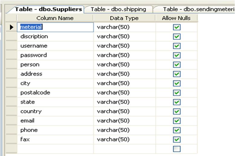
  • These details are stored in database using MS-SQL server 2000 where these data is stored in the form of Tables.
  • Similarly data is stored for manager,employee in database.
  • Admin can add new shipping address Requirements
  • When admin wants to add new shipping address
  • He can by filling the add new shipping address form

Manager

  • Orders material requested by employee
  • Gets the information of material supplied to employee from supplier.
  • Logins by using username,password and Type-manager
  • He can view his personal details, employee details and supplier details.
  • He gets the details of the material supplied to the employee.
  • He can delete employee details from database
  • Approve material
  • This information is given to manager by employee.
  • Received material information is forwarded by supplier
  • When supplier delivers material to employee.

Employee:

  • Third module
  • Logins by using user type-employee
  • Views personal details, supplier details, received materials, requested materials.

Supplier:

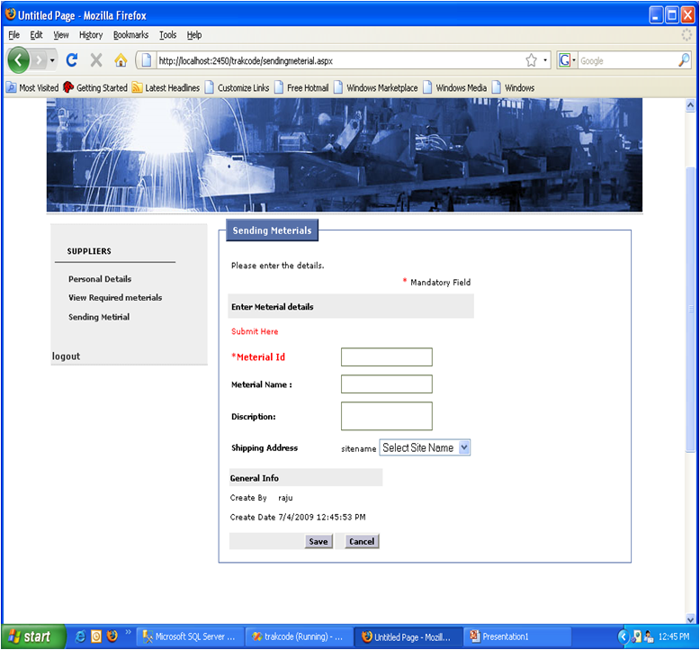
  • Sends material to the employee directly
  • Gives information of the material delivered to employee ,to the manager.
  • i.e both manager and employee can view received material
  • Delivers the material from shipment
  • He can view personal details, requested material and send material

SOFTWARE REQUIREMENTS

Operating System      :        MS Windows

Languages                   :        Asp.Net with C#

Database System       :       MS-SQL Server

Download this Track Machine Management for Railways .Net Project Source Code & Database.

Time Sheet Management System .Net Project

The main aim of developing this Time Sheet management System .Net Project is to provide automated work Time sheet for allocated projects all employees in the organisation.

The main Users are Employee, Manager and Admin.

Employee functionalities:

where employees can login with their credentials and view their details, modify existing details, enter new time sheets, view time sheet, update time sheet, delete sheets

Manager functionalities:

Where manager has actions like release, update, view, change & allocation time sheet functions.

Admin functionalities:

Where admin can add employees, approve time sheets, create projects, view projects, create employee id’s, project billing actions, etc.

Database Tables below:

Project Table:


Column Name Data Type
UniqId int
ProjectId Varchar(50)
Project Name Varchar(50)
Started Date Varchar(50)
Estimated Date Varchar(50)
Client Name Varchar(50)
Client Location Varchar(50)
Address Varchar(50)
Poc Varchar(50)
PO Varchar(50)
Scope Document Varchar(50)
Estimated Cost Varchar(50)
Types Varchar(50)
Pay For Manager Varchar(50)
Pay For Employee Varchar(50)
Technology Required Varchar(50)
Data Bases Varchar(50)
AssgineTo Varchar(50)

Employee table:

Column Naame Data Type
UniqId int
EmpId Varchar(50)
First Name Varchar(50)
Last name Varchar(50)
Password Varchar(50)
Gender Varchar(50)
Phone Number Varchar(50)
Email Varchar(50)
AltEmail Varchar(50)
Experience Varchar(50)
Date Of Join Varchar(50)
Address Varchar(50)
City Varchar(50)
State Varchar(50)
Country Varchar(50)
Pincode Varchar(50)
Position Varchar(50)
Status Varchar(50)

Timesheet Table:

Column Name Data Type
TimeSheet Id int
EmpId Varchar(50)
Date Varcar(50)
Analasys Requirement Varcar(50)
Preparing Functional Design Document Varcar(50)
 Preparing High Level Design Varcar(50)
  Preparing  Loe Level Design Varcar(50)
   Writing Code Varcar(50)
  Preparing Tcehnical Design Document Varcar(50)
Analasys & Fixing Bug Varcar(50)
Unit Testing Varcar(50)
System Testing Varcar(50)
 Integrity Testing Varcar(50)
Preparing Test cases Varcar(50)
Totaltime Varcar(50)
Status Varcar(50)


Column Name Data Type
Allocated Id int
Allocated By Varcar(50)
Project Id Varcar(50)
Project Name Varcar(50)
Allocated To Varcar(50)
Status Varcar(50)


Column Name Data Type
Uniq Id int
Project Id Varcar(50)
Emp Id Varcar(50)
Total Work Hrs Varcar(50)
Payment Varcar(50)

Download the Time Sheet Management System .Net Project Source code

College Visitor Management System .Net Project

Abstract: “College Visitor Management System” is a process of managing the information of the visitors visiting the College campus. For any organization maintaining the information of the visitor is a very major issue. This system will replace the manual maintenance system and will help the authorities to keep track of the visitors visiting the campus.

This software is being build with help of ASP.NET. The data of the new visitors visiting the campus will be stored in the database. With this system the visitor’s information can be stored in the database, so that in the future it shall be used for the reference. The data will be stored in the SQL SERVER as the backend. This software will help an organization to do the job effectively and give an all round development of the project.

The major features of the College Visitor Management System are:

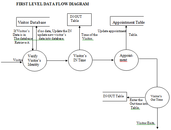
  1. The in and out time of the visitors is stored in the database.
  2. Name, address and all other information regarding the visitor.
  3. There will also be provision to retrieve the data from the database for the future references.
  4. The reason for which the visitor is going to visit the campus.
  5. When the visitor visits the campus for the first time he/she needs to register. He/she will be provided with an id so that whenever he/she wants to visit next time they can refer through this particular id.
  6. Appointments of the Visitors with the Faculty will also be stored in the database.

Requirement Analysis

Module:

College Visitor Management System

Overview Statement:

The purpose of this module is to store the information of the visitor’s visiting the campus.

Customer:

Visitor

System Functions 

Ref # Function Category
R 1.1 Visitor should be able to add his details. Evident
R 2.1 System should be able to save the new visitor details. Hidden
R 1.2 Visitor should be able to get the appointment from the faculty. Evident
R 2.2 System should be able to save the appointment time & intimate the visitor about the availability of the concerned faculty. Hidden
R 1.3 The security personnel should be able to update the IN time of the visitor. Evident
R 2.3 System should be able to inform the concerned faculty regarding the visitor. Hidden
R 1.4 After the visitor had paid his visit to the concerned faculty, the system should save it. Hidden
R 2.4 System should inform the security post that the visitor has met the faculty/staff. Hidden
R 1.5 The security personnel should enter the OUT time of the visitor. Evident
R 2.5 System should be able to save it. Hidden

 System Attributes 

Attribute Detail and Boundary Constraint
Software Microsoft ASP.NET
Hardware Web Camera, PC with 250 GB hard disk & 4 GB RAM.
Network Local Area Network

 List of Use Cases and Scenarios

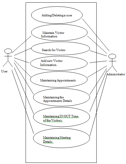
 Use case # 1 /Maintaining Users

Scenario # 1 / Adding a User.

Scenario # 2 / Deleting a User.

Use case # 2 / Maintaining the Roll

Scenario # 1 / Adding a new Roll.

Use case # 3 / Maintaining Visitor information.

Scenario #1 / Adding a new visitor.

Scenario #2 / Editing the Visitor information.

Scenario #3 / Searching for a Visitor Data.

Use Case # 4 /Maintaining Appointments

Scenario # 1 / checking the appointments of the faculty.

Scenario # 2 / Fixing the Appointment for the visitor.

Use Case # 5 / Maintaining the Appointments details.

Scenario # 1 / Reason of the Appointment.

Scenario # 2 / Faculty/staff member with whom the visitor wants to meet.

Use Case # 6 /Maintaining the meeting details.

Scenario # 1 / IN & OUT time of the visitor, meeting with the faculty/staff.

Use Case Diagram:

Data Flow Diagram:

PROJECT FORMS

Form 1 Homepage

• This is the Home Page.
• The user needs to type http://localhost/College/webform2.aspx in order to get this page.
• There is a calendar showing the current date and year.
• There are two hyperlink buttons on this page
o NEW VISITOR
o SEARCH
• On the left hand side of the form there are 3 hyperlinks
o About NIST
o FACULTY
o COURSES OFFERED

Form 3. New Visitor Entry Page

• When the user clicks the NEW VISITOR button from the homepage this page is displayed.
• The user enters the necessary data in this form and clicks the Save button in order to save the data in the database.
• After the data has been saved the user clicks the Home page in order to return to the Homepage.
• If the user wants to refresh the data entered he/she has click the refresh button.

Form 2. Search Page

• This page is obtained on clicking the SEARCH button from the Homepage.
• The user needs to select anyone of the search criteria.

Form 2.1 Search form where the search criterion is Visitor ID.

• The user enters the visitor id and clicks the search button.
• The entire detail of the visitor is displayed in the data grid.

Form 2.2 Search Form where the search criterion is name.

• The user enters the first name of the visitor and clicks the search button.
• The entire detail of the visitor is being displayed in the data grid.

Form 2.3 Search Form where the search criterion is Place

• The user enters the place and clicks the search button.
• The entire detail of the visitor is being displayed in the data grid.

Form 2.4 Search Form where search criterion is Date.

• The user enters the date in the mm/dd/yyyy format or selects the date from the calendar as shown in the above form.
• The entire detail of the visitor is being displayed in the data grid.

Form 3 Visitor Detail Page.

• When the user clicks the SELECT hyperlink from the data grid, this page is being displayed.
• The user clicks the Appointment button to move to the Appointment page.
• The user may click the Home button to return back to the Homepage.

Form 4.1 Appointment Form.

• This page is displayed when the user clicks the appointment button from the visitor details form or enters the visitor id in the search page and clicks the appointment button in the search button itself.
• The user then clicks the show calendar button to display the calendar.

Form 4.2 Appointment Page showing the calendar.

• The user selects a particular date from the calendar, which is being displayed in the textbox (mm/dd/yyyy format).
• Then the user selects the faculty with whom the appointment is to be taken.
• The image of the faculty is being displayed in the faculty/staff image box.
• Then the user mentions the reason for appointment and selects the timing.
• The user then clicks the save button to display the batch.

Form 5. Faculty Information Page.

• The user may select any of the hyperlink in order to display the page showing the information regarding the concerned faculty.

Multi Level Marketing Java Project

Abstract:

Now a days the e-commerce website and the study type materials are different so difficult to purchase and time taking process. In this Multi Level Marketing project we are providing both e-commerce and study materials in this project you can buy laptops, mobiles, etc., and also know the study information.

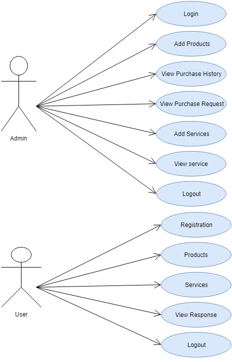
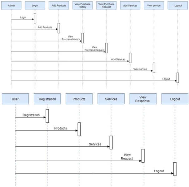
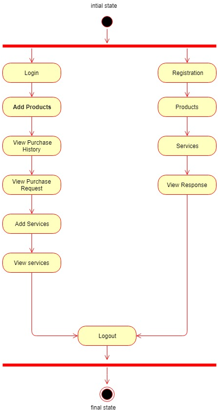
In this Multi Level Marketing project the admin can login and add products, accepting the user requests and also accept the purchase requests, know the purchase history and add the services. Students who are registered can login and see the products and purchase it, and student can also view the services which are added by the admin.

In this Java project there are two modules

1) Admin

2) User

Existing System:

In the existing system the e-commerce website and the study type websites are different so difficult to purchase and time taking process.

Proposed System:

In the proposed system the both e-commerce and study type materials are in the same website and the user can easy to select and purchase.

UML Diagrams:

Use Case Diagram:

Sequence Diagram:

Activity Diagram:

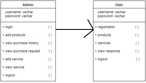
Class Diagram:

 Software Requirements:

  • Operating System :  Windows
  • Database :  MySQL
  • Technology :  Java/j2ee,JDBC,Servlets,JSP
  • Web Technologies :  Html ,CSS, Java Script
  • Web Server :  Tomcat
  • IDE: Eclipse/ Net beans

Output Results:

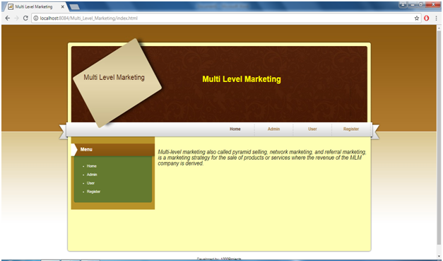
Home Page:

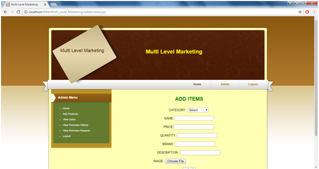
Add Items Page:

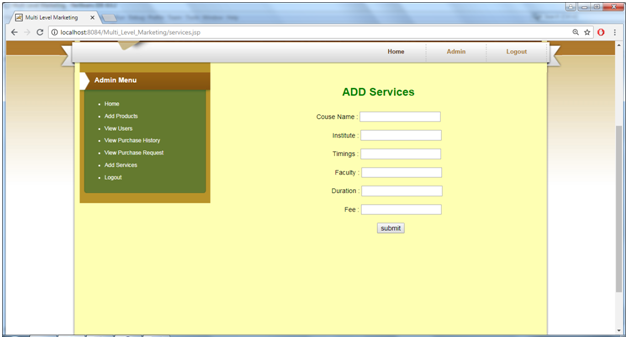
Add Services Page:

All Output Functionalities:

  • Home:
  • Admin:
  • Admin Home:
  • Add Products :
  • View Users:
  • View Purchase History:
  • View Purchase Requests:
  • Add Services:
  • View Services :
  • Registration:
  • User Login:
  • User Home:
  • Products:
  • Search Services:
  • View Services:
  • View Response

Local Vendor Review System Java Project

Abstract:

Local Vendor Review System is a web based application developed by using Java and MySQL Technologies, this application is mainly for the customers who are interested in food. Now a day there is no proper way to get the Restaurant Information whether which is providing quality food or not, but this application helps to find good restaurants. This project is developed to improve the quality of the services provided by vendors. There is an option to give feedback of the restaurants so that customers can easily find the restaurants.

Existing System:

In the existing system we don’t have any feature to find the restaurant, we directly go to restaurant and have some food then only we will get to know the food quality and services of the restaurant.

Proposed System:

In this proposed system the customer has an option to give his/her feedback to the particular restaurant so that the user can easily find the better restaurants.

UML Diagrams:

Use Case Diagram:

Sequence Diagram:

Activity Diagram:

Class Diagram:

Modules:

Admin:

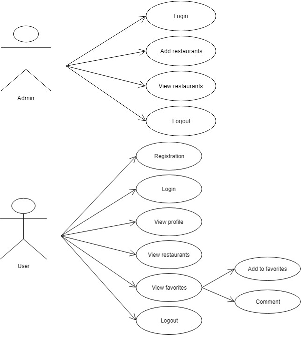
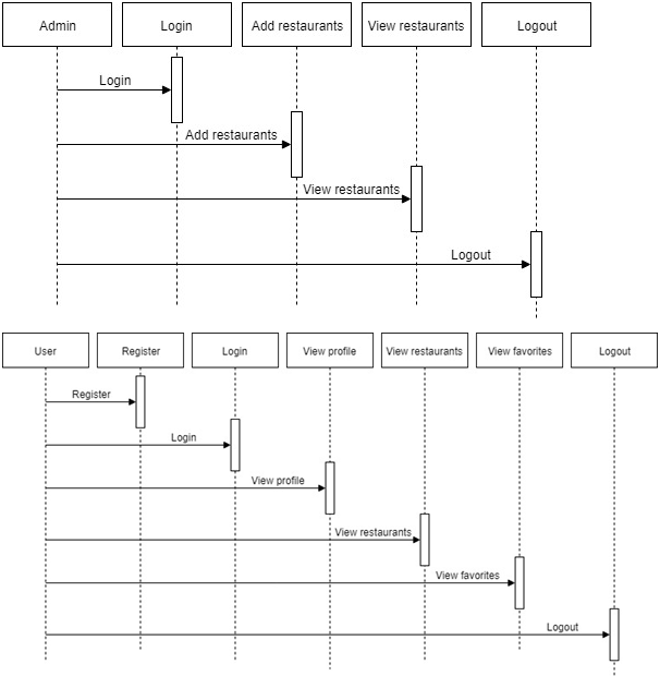
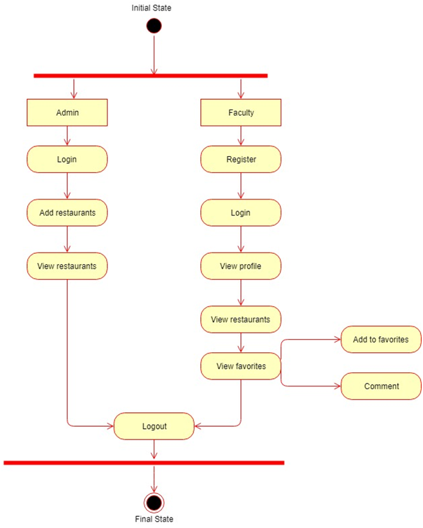
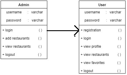
Admin needs to get login by entering valid credentials.  Admin can add the area wise restaurants details.  Admin can view all the restaurants.

Customer:

Customer needs to enter all the details in the registration form to get a valid username and password. Customer can see his/her profile information and customer can search restaurants by location or area wise. Customer can find the restaurant details and add restaurants as his/her favourites.

Output Results:

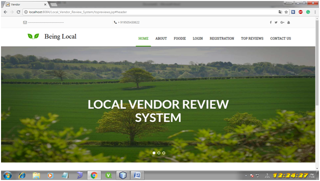
Home Page:

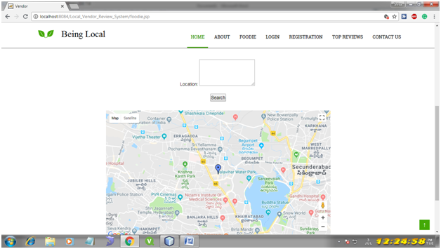
Foodie Page:

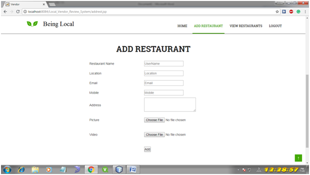
Add Restaurant Page:

Software Requirements:

Hardware Requirements:

Processor-Intel Core, RAM-2 Gb , Hard disk-500 Gb.

Software Requirements:

Operating System-Windows 7/8/10, Front End-HTML, CSS, JavaScript NetBeans7.4, JDK 1.7, MySQL 5.5, SQLYog, HTML, JavaScript and CSS.

All Other Functionalities:

  • Home:
  • Foodie:
  • Admin Login:
  • Admin Home:
  • Add Restaurant:
  • View Restaurant:
  • Registration:
  • Customer Login:
  • Customer Home:
  • Profile:
  • View Restaurants:
  • View favourites:
  • About Us:
  • Contact Us:
  • Top Reviews:

Citizen Card System Java Project

Abstract:

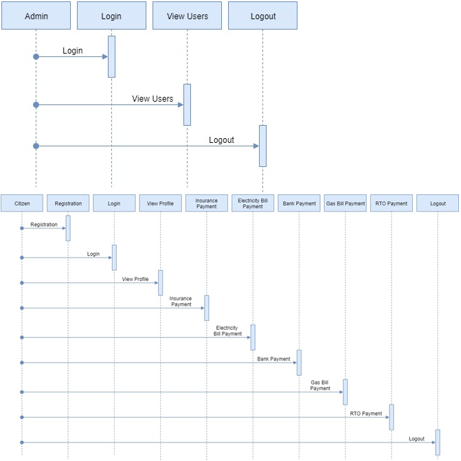
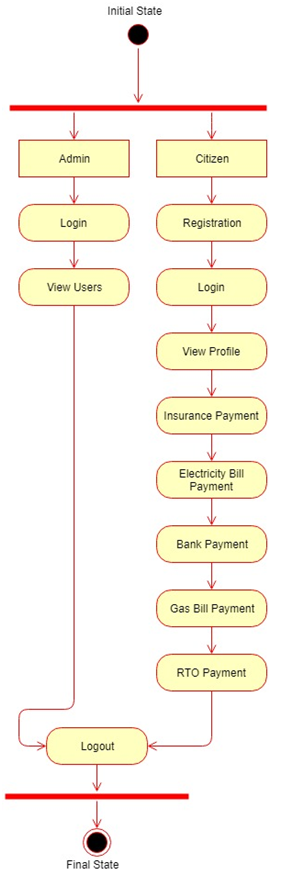
The project ‘Citizen Card system’ provides us the data regarding the citizen of a country. Every citizen has a unique Id to trace the personal data in each and every division or service that he enters. The data can be traced using the unique Id of that particular city.

In case a citizen wishes to use the services or utilities of the Government or private institutions, he ought to go to the various divisions with varied IDs for that specific division. But a citizen card allows the citizen to enjoy all the services and utilities under a single card. The citizen card system assists us in gaining data regarding the services or utilities as well as providing data regarding the conduct of the citizen in credit rating.

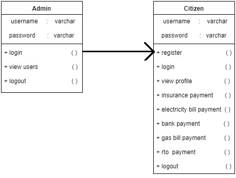
UML Diagrams:

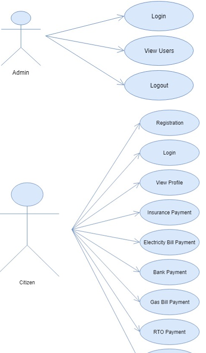
Use Case Diagram:

Sequence Diagram:

Activity Diagram:

Class Diagram:

Existing System:

The existing system is a system operated by humans and the citizen requires to reserve his data through excel sheets or disk drives, but there is always a risk of losing the data due to mismanagement.

Proposed System:

The proposed system is more user-friendly and makes the entire project maintenance very uncomplicated and manageable. This system motivates people to get the Citizen Card, which is a multi-purpose card. This is a socially responsible website and functions on the principles of citizen data and strengthening citizen safety in the country.

Output Results:

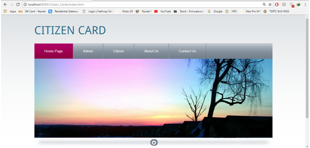
1. Homepage


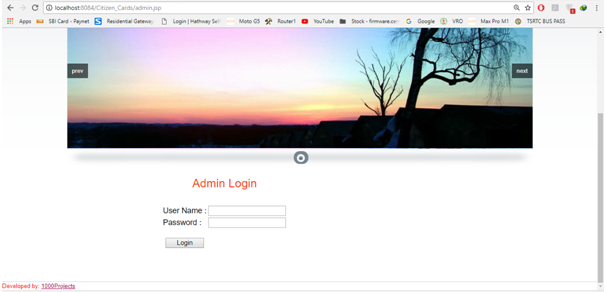
2. Admin Login Page

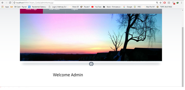
3. Admin Home Page

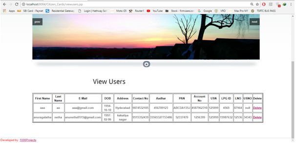
4. View Users


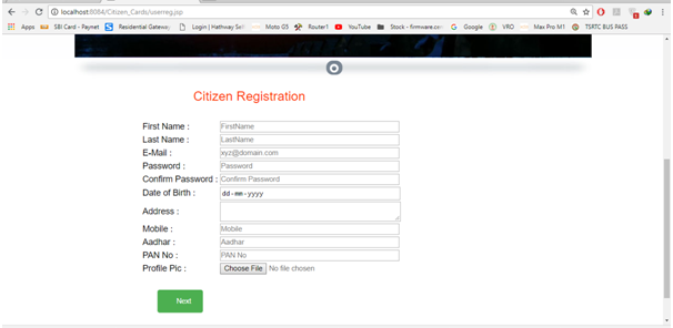
5. Citizen Registration

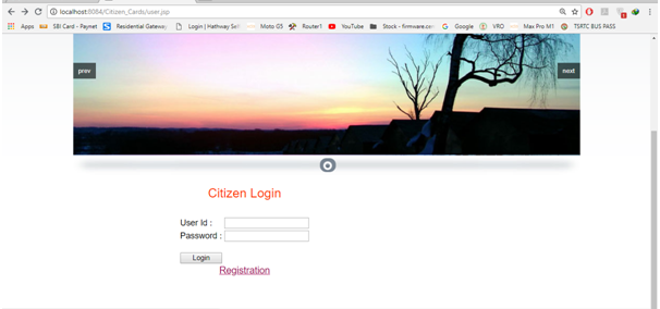
6. Citizen Login


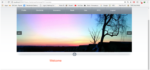
7. Citizen Home


8. View Profile

9. Insurance Info

10. Electricity Bill Payment

11. Bank Bill Payment

12. Gas Bill Payment

13. RTO Bill Payment

Software Requirements:

  • Operating System:  Windows
  • Database:  Oracle
  • Technology :  Java/j2ee,JDBC,Servlets,JSP
  • Web Technologies:  Html , CSS, JavaScript
  • Web Server:  Tomcat
  • IDE: Eclipse/ Net beans

Online Entertainment Portal Java Project

Abstract:

Online Entertainment Portal is a web application which is used to provide services of Movies With options like online Streaming, buy option. It’s a good Platform Which Connects Sellers with customers who are Movie Lovers. Apart from this we have books section for book lovers And a customer Buy from Seller.
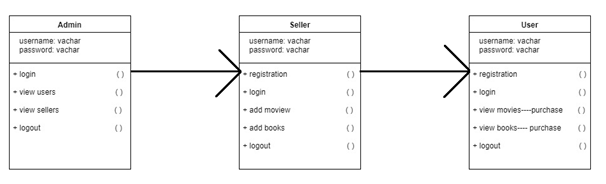
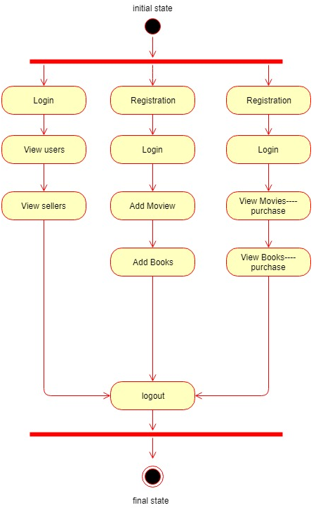
UML Diagrams:

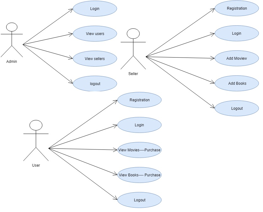
Use Case Diagram:

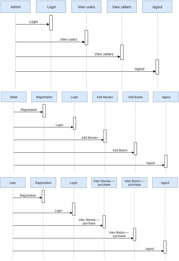
Sequence Diagram:

Class Diagram:

Activity Diagram:

This System includes 2 Modules

ADMINISTRATOR

He has the full authority over the website. He can View all the registered sellers and users, has the access/power to delete them, he can also edit the website like update them regulary. He is responsible for safety of information which is provided by both the users/customers and sellers who by their product on this site.
CUSTOMERS

There are generally 2 types of customers over here

  1. Users :-

They use the site to stream movies/videos and read books and try to Register for an event. Users have two options either they can buy a Movie if they buy it a Dvd will be delivered to them for which prices are to be paid

  1. Sellers:–

They use the site to sell their products like movies, books. They decide the price of their products and regularly need to update about the quantity of product present with them.

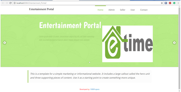
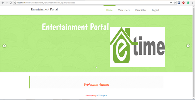
Output Results:

Home Page:

Admin Home Page:

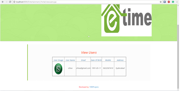
View Users Page:

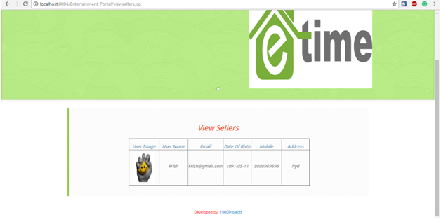
View Sellers Page:

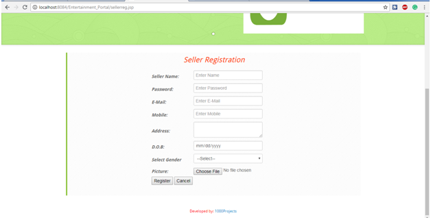
Seller Registration Page:

All Output Screens:

  1. Home page:
  2. Admin login page:
  3. Admin home page:
  4. View users page:
  5. View sellers page:
  6. Seller registration page:
  7. Seller login page:
  8. Seller home page:
  9. Add movies page:
  10. Add books page:
  11. User registration page:
  12. User login page:
  13. User home page:
  14. View movies page:
  15. Movie Details page:
  16. Purchase page:
  17. View books page:
  18. Book Details page:
  19. Purchase page:
  20. Contact us page:

Software Requirements:

  • Operating System :  Windows
  • Database :  MySQL
  • Technology :  Java/j2ee,JDBC,Servlets,JSP
  • Web Technologies :  Html ,CSS, Java Script
  • Web Server :  Tomcat
  • IDE          : Eclipse/ Net beans

Collaborative Online Tutorial System Java Project

Abstract:

Now a days Tutorial Points are becoming useful to the students who are in the search of quality education. So, this application provides the support for both the tutors and students. The Admin is the head of this application who can view the students and tutors registered into the application. Admin will add the courses. The tutors who need to be registered and login and can select the course he would like teach by providing location and timings.

Students who also need to register and login into the application while registering student will give the location and after logging when he selects the course. The tutors available in that location and the course that tutor can teach both are matched and the request will be sent to admin. Admin will confirm the request therefore student can view the tutor details.

UML Diagrams:

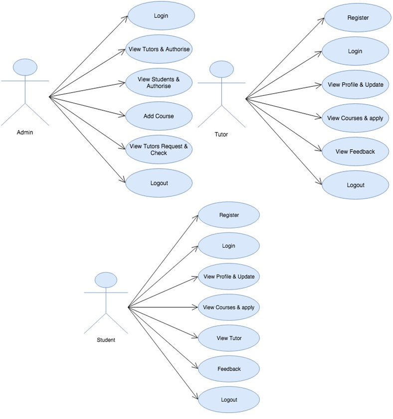
Use case Diagram:

Sequence Diagram:

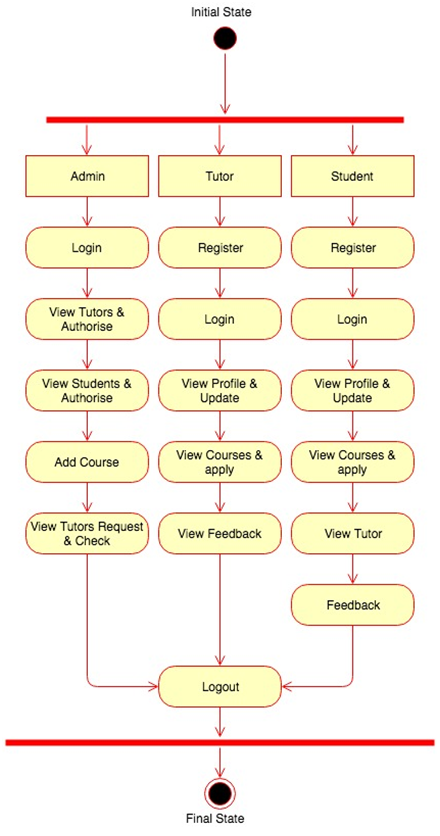
Activity Diagram:

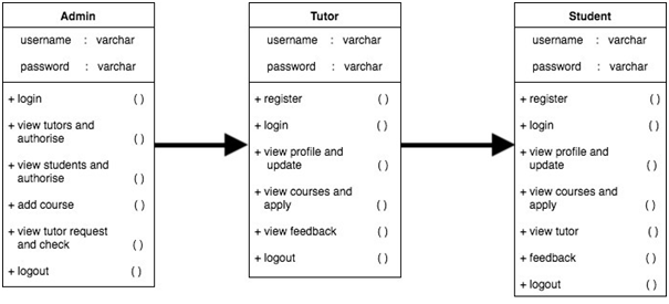
Class Diagram:

There are 3 Modules present in the application:

  1. Admin
  2. Tutor
  3. Student

Admin:

Admin will login with the default username and password. Admin can view the registered tutors and students. He can also view the requests from tutors. Admin will confirm the requests then the details of tutors are shown to student and the tutor will be assigned to student.

Tutor:

Tutor will login and register into the application by giving the username and password, after logging in tutor will select the course and location and the timings with his availability. If any student requests were there in that locality the tutor will be assigned to student. 

Student:

Student will register and login into the application by giving username and password and student need to select the course and timings and if any tutors available in that area the request will be forwarded to admin, admin will confirm the request the tutor will be assigned to student.

Existing System:

In Existing System, the users need to visit the nearest tutorial point and there after he need to enquire the courses and the availability timings of the tutor. This makes the process lengthy and complicated.

Proposed System:

In Proposed System the tutors and students will registered and based on the student’s locality the tutors will be mapped by the timings selected by the student, this makes the whole process simple and effective.

Output Results:

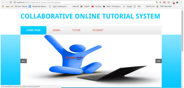
Home Page:

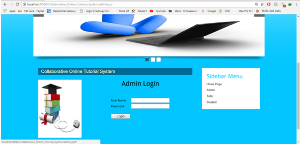
Admin Login Page:

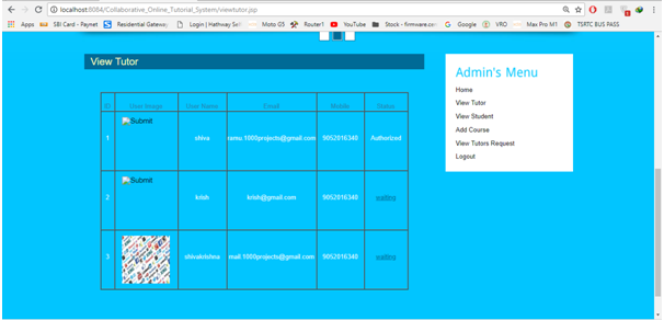
Admin View Tutor Page:

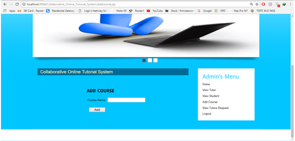
Admin Add Course page:

All Output Results:

1.Homepage
2.Admin Login
3.Admin Home
4.View Tutor
5.View Students
6.Add Course
7.View Tutors Request
8.Tutor Registration
9.Tutor Login
10.Tutor Home
11.View Profile
12.View and Select Courses
13.View Feedback
14.Student Registration
15.Student Login
16.Student Home:
17.View Profile
18.View and select courses
19.View Tutor
20.Feedback Page

Software Requirements:

Hardware Requirements:

Processor-Intel Core, RAM-2 Gb , Hard disk-500 Gb.

Software Requirements:

Operating System-Windows 7/8/10, Front End-HTML, CSS, JavaScript NetBeans7.4, JDK 1.7, MySQL 5.5, SQLYog, HTML, JavaScript and CSS.