Final Year Electrical and Electronic EEE B Tech & BE project

The final year Electrical and Electronic EEE B Tech & BE project is based on Analysing of Bangladesh power system. The data is based on their requirement of the major components and according to full details from the Power Generation Company Bangladesh (PGCB).

Company all the major components like Buses,Generator,TapTransformer,Capacitor,Motors and Loads are given the counting by the company itself But, this tool is Identify to analyse contingency of the power system. To do this we take details from the database.

Total Project Report Components & Roles:

The Major role is to perform the selection operation from the database.to, perform this suitable software to analysis this which new product available in market. Select all the information from the PSAF. The PSAF (power system application Framework)This framework is taking care of the table entry data and picture or graphical mode data ,the diagram which are in single line for drawing options other one is Generating for report to simulation. The framework is developed by CYME international TD Inc. This is the tool we can use for perfect matching in Bangladesh system to collect. The version is used for this PSAF 2.81(Revision 2.8).this is the overall operation to perform the PSAF.

The constructing the data base data should select the suitable for the software, it come constructing the network, we provide all the information from the PGCB in PSAF. All the network select can run the process of the simulation. The Simulation is the process which is run the real time process on all time, and this takes the abstract level of the system all the times. Simulation take the all the information form the source.

By taking the data from the table creates low power voltage problem. By this we can use to solves the problem is Newton-Rap son, and this the method take all the fault conditions and solves the first.

Download Engineering Final Year Electrical and Electronic EEE B Tech & BE project Report, Abstract, Documentation and PPT Seminar.

Signal Flow Graphs seminar topic

This Signal Flow Graphs seminar topic explains you about the signal flow graphs and how the signal flow graphs are used in the control systems, the network analysis, and signal flow graph consisting of the graphs. It consists of nodes and branches and we have to use mesh and nodal analysis. Signal flow graphs represent the multiplications and additions it represent the relation of cause and effect relation, porting technology used these graphs, two port networks. signal flow graphs used to represent the servo control system, the analysis like mesh and nodal are done each and every loops, signal flow graphs are done using series rule, parallel rule- having common node and it has one incoming and one out going wave and those are combined, parallel rule- branches connect one node to another, self loop rule begin and end of node, splitting rule- split the one node into two are more nodes. This ECE technical paper mainly used for simplify the complex networks, and in metabolic control analysis in this solve the equations and write in the form of matrix form and also provide the visual frame work to analyse cause and affect relationship.

Download Signal Flow Graphs seminar topic and Technical paper presentation.


Remote Tap Changer Control Panel Seminar Topic

This seminar topic explains about the Remote Changer Control Panel also called RTCC, the main of this topic is to control the output of the transformer, the output voltage is achieved based on the controller of the remote tap changer control panel, the output voltage of the transformer maintained using the automatic voltage regulator (AVR), this AVR is arranged inbuilt manner, based on this the output of the transformer is controlled, RTCC mainly consisting the automatic voltage regulator, switches for selection purpose automatic selection, in the automatic mode the voltage is controlled by AVR and in the manual mode based on taps the voltage is raised or reduced, OLTC (on load tap changer) motor is used in clockwise and anti clockwise, OLTC control the two or more transformers continuously.

This topic explains you about the on load tap changer- this OLTC used in high voltage transformers which having high capacity, OLTC (on load tap changer) consists of LCP (low control panel) and RTCC, AVR sense the low voltage and comparator used here to compare the low voltage with initial value, it is suitable for the bidirectional power flowing (forward and backward directions), current rate is up to 500 MA, OLTC can be connected to desktop and laptop.

Download Remote Tap Changer Control Panel Seminar Topic and Paper Presentation.

Power Former Seminar Technical Presentation

The main aim the Power Former Seminar Technical Presentation is to generate more power using the power former. Power utility increases day by day for industries, home appliances, corporate companies, A / C usage increases, so to avoid the power problem we have to generate the power in an efficient manner. This technical paper can done this, and this document gives us details of the power generation and transmission and provides the details how the power is generated in an effective manner, here in this  we are using step – up transformers, this is used here to step up the voltage value, if the plant generated 40 k v then it step up to 900 k v, but the drawback in this equipment is less efficiency, and more maintenance cost, area taken more for manufacturing, power former is a 3 phase ac generator, the components used here are generator, generator circuit breaker, step up transformer, line circuit breaker,  stator design should be innovative, the types of winding consisted in the power former are outer semiconductor layer, inner layer, solid insulation, standard conductor. So by using the step up transformers in the plants we can generate the more power, so that high voltage is generated.

Download Power Former Seminar Technical Presentation with full documentation.

Phase Sequence Detection and Controlled Power Supply System Project

This Phase Sequence Detection and Controlled Power Supply System (EEE) project mainly used to find the phase sequence of any machine or other electrical equipment and it works on three phase supply and the extra feature added in this project is controlling the power supply voltage and also provides the concept of over and under voltage protection. in this electrical project three phases are used namely  R Y B (red, yellow, blue), if the order is not in a manner then the total circuit winding will be damaged, when the high voltage is applied to the system then that is more than the required range then the circuit and finally it will be tripped, this can be done by using the relay  and high voltage protection system, with the help of this we can protect our electronic equipments, can provide more efficient and simpler to maintain the phase detection, this project is mainly used in sub stations, because the power from the power plant can send to the sub stations then next send to the homes, agriculture areas, industries, here industries are having separate line for power transfer, so in the sub stations we have to set the phase sequence, where it should be in a sequence of R Y B.

Download Phase Sequence Detection and Controlled Power Supply System Electrical and Electronics Engineering EEE Project Report

Differential Drive Robotic Rover project

The main aim of this Differential Drive Robotic Rover project is to whenever obstacle finds the robot then takes the diversion from that position. The obstacle can be founded by using sensors, here the robot consist of two motors, each and every motor control the operation of the vehicle moving forward, backward, left and right this can controlled by the  remote. IR rays are used for the detecting the vehicle, there are two main parts are working with the IR those are emitter, detector in this emitter emit the infrared rays and detector detect if any obstacle is present in that motion of moving, this type of robot mainly used in the industries. Here in this project use the microcontroller because the sensor send a signal to the microcontroller then it controls the operation, here separate sources are required for the motor and the microcontroller.

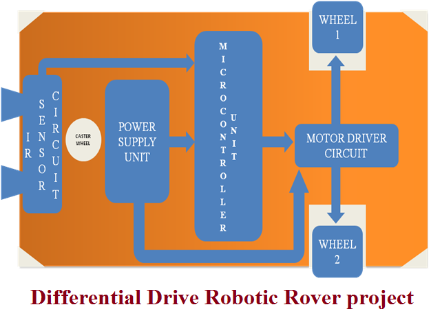
The robot consist of power supply unit, battery charger unit, IR sensor circuit, microcontroller unit, motor driver, and DC motor, power supply required for the microcontroller and motor is different, 5Volts for the microcontroller, 12volts for the motor driver circuit, design of IR sensor circuit, the microcontroller used here are AT89C51, 256kb of RAM, interrupt handling, interrupt recovery time and this robot is most reliable and cheap around 2000/-only.

Differential Drive Robotic Rover project

This project architecture works with IR Sensor circuits and these are directly connected to the micro controllers with motor driver circuits as well as power circuits and different wheels.

Download Differential Drive Robotic Rover full project document and report, Paper presentation, seminar topic.

Collide Vehicle Information Capturing Using Gps and Gsm Technologies Project

The main aim of this Collide Vehicle Information Capturing Using Gps and Gsm Technologies project is to get the vehicle information using the GSM and GPS technologies, this GSM is the global system for mobile (to get the vehicle information using SIM (subscriber identity module)), and GPS (global system for mobile) is used to find the vehicle location and to get the information when the accident occur, in this project the components used are accident switch, microcontroller, GPS modem, GSM modem, buzzer, ADC analog to digital converter, LCD- liquid crystal display, the software used are embedded c, keil IDE software, this project is mainly used in the industrial usage, coalmines, transportation system, object recognition,  whenever accident occur then the sensor detect the vehicle and give the information based on the threshold value selected, if the threshold value exceeded then sensor give the information to the microcontroller, and the sensed data is in the analogy form then the data has to convert to the digital form, this can be done using the analogy to digital converter, then this digital data send to the microcontroller, then compare this value with fixed threshold value, if the threshold value exceeds then the microcontroller send the information to the mobile using GSM, to find exact location using the GPS.

Download Collide Vehicle Information Capturing Using Gps and Gsm Technologies Project Report and Full Documentation.

4G-Mobile Communication Systems seminar topic

This 4G-Mobile Communication Systems seminar topic is mainly explain you about the 4G mobile communication systems, this technology is the successor of the 3G communication system, it provides ultra broadband internet access, it means wireless services are provided, it supports video calling, 3D television. Nowadays 4G technology is used because it provides 100MBPS speed; the data rate is 1GBPS in stationary times. 3G technology is designed it can support up to 2mbps, compared to 3 rd generation technology 4th generation is having more features higher interactivity (comfortable interface), higher connectivity (better connection), dynamic self reconfigurability (can change the equipments when problem occur), voice recognition, provide good security, it provides the features of internet access, radio access, platform, display, RF component.

It support mobile IP, GPS technology support, effective handover algorithms, user interface technology,   these are the services provided by the 4G technology. To use the 4G technology we should have the network in rural areas even they don’t have the 3G signal network, so by taking the 4G supported mobile there is no usage to that type of customers, 4G provides the high data rate, recently 4G supported mobiles are manufactured and released in to the market, I phones are supporting the 4G technology. 

Download 4G-Mobile Communication Systems seminar topic and Paper Presentation Report.

3-Phase Minor Electrical and Electronics Engineering EEE project

3-Phase Minor (EEE Project):

                The main aim of this 3-Phase Minor Electrical and Electronics Engineering EEE project is to explain use of three phase minor, in this project we use the three transformers, these three transformers of type step down transformers, these transformers convert the high voltage to low voltage that is 230 volts AC to 12 volts AC, now these AC voltage is convert to the DC voltage rectifier, here in this project we use the IC (integrated circuit chip) this is the electronic chip, it requires only 5 volts so here we use the voltage divider to divide the voltage, this signals are given to the operation amplifier (op amp) of type LM 324 type, the output of operational amplifier shown digital form, 0’ s and 1’ s this digital data display on the LED’ s. the components used in this project are transformers (step down), rectifiers (to convert ac to dc), capacitors, resisters, op – amp of type LM324, LED’ S, voltage regulator (voltage controller), power supply. This project is mainly used in big industries, power plants, this equipment is controlling the three phases of the transformers, the 3 phase supply is transferred by using this project, and finally this project is very complex and should be maintained in a safe position.

Download 3-Phase Minor Electrical and Electronics Engineering EEE Final Year project report Documentation and Paper Presentation seminar topic.

Final Year Project on Robotic Car

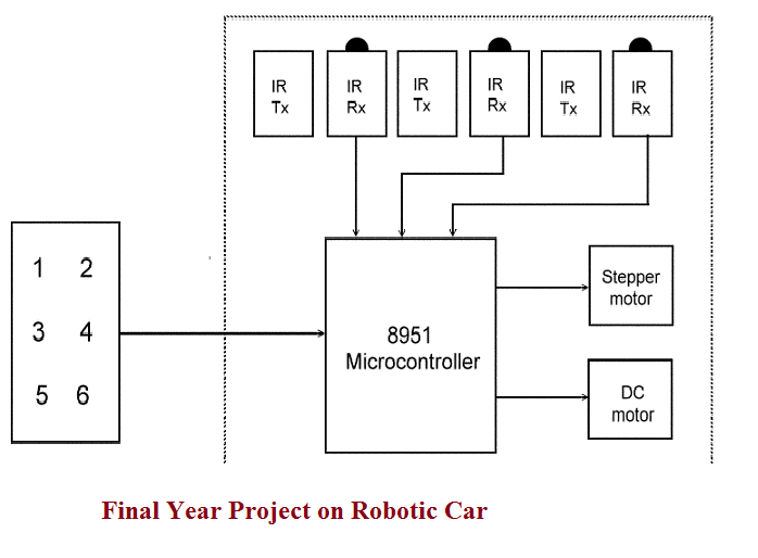
The main objective of developing this Robotic car is to provide automatic method for controlling of microcontroller based electronic robotic vehicle. Here we have used Keyboard based operations to move the positions and speed of the car, keyboard prepared in this application is looking like computer keyboard and has the functionalities like left key used for turn left the car wheels and position, right key used for turn right the car position, enter button used to stop and start the car. Simple motors and stepper motors, micro controllers, transmitters, receivers, LCD displays, LED equipments used to impalement total robotic movement system. 8951 Microcontroller connected to the keyboard and operations can be done by car operators in the vehicle control room. IR transmitter and receiver sections, Stepper motor, DC motors directly connected to micro controller in the circuit diagrams.

final-year-project-on-robotic-car

Download Final Year Project on Robotic Car and total Project Documentation, paper Presentation, Seminar Topic.