Women Protection System Mobile Application

In this Women’s protection system project mobile application is to be implemented that inform the predefined numbers about the safety and location of the user. The application is accessible automatically as well as manually.

Requirements from Android APP:

– Android App constantly monitor the Bluetooth connection between mobile and hardware.

– System can be deactivated by entering the password on the mobile and after that even  if the  key is pressed or connection between mobile and hardware is broken then message will NOT send.

– When mobile received signal via Bluetooth,after pressing key on the belt(Hardware side), App will fetch the current GPS location and Emergency message to predefined numbers using SMS method.

– When Bluetooth connection ( between hardware and mobile) broken( by forcefully opening belt ),or if link between mobile and hardware is disconnected,then App will generate alert command and send last recorded GPS location to predefined numbers.

– If unintentional person want to switch off mobile to remove the communication medium, App will display any wrong message,

Example. “Do you really want to switch off your phone?”

The right answer for this is NO to switch off phone,which is only known to user of that phone but as obvious answer is YES,that unintentional person will say YES.

Because of this before switching off,Mobile will send current location via  SMS without knowing to that unintentional user saying”I am in danger please follow my GPS location”.

Analysis of the International Fashion Retail Brand

Executive Summary:

This content of this presentation consists of analysis of the International fashion retail brand. This paper mainly focuses on the operational strategy technologies which are being adopted by fashion retail brand which makes them stay far ahead from competitors. The study was carried out on supply chain management and logistics management strategies of fashion retail brand. How could they meet the challenges and market demands parallel to capturing new markets like opening one stare every day across the globe on an average and around 500 stores in a year. The corporate governance policy, the technology, the manufacturing, Research and development concepts which are contributing to their business growth. How they are striving to make their product to be proffered by customers. The Standard operating procedures, the product positioning, Innovation, Quality, pricing, the work scheduling, new trends, the people and the processes were analyzed to understand the success stories and challenges and the gaps. There were few gaps which were Identified and the recommendations were given in technical aspects analysis.

The fashion retail brand is an flagship brand of Inditex incorporated in 1975 in Spain. The fashion retail brand is has its presence in 88 countries with 6500 Stores. The fashion retail brand is growing in such a phase of opening one store every day and an average of 500 stores in a year. The main business objective of fashion retail brand is “ Link customer demand to Manufacturing and link Manufacturing to Distribution. The Main range of fashion retail brand are Men’s, Women’s and Kid’s fashions.

The fashion retail brand has got its Global Head Quarters at Arteixo which is beside La Coruna the same is the head Quarters for fashion retail brand Home which are two brands out of eight Inditex brands. Apart from these fashion retail brand has Head quarters based on states and countries. The fashion retail brand has got Manufacturing setup here and half of their production is being done here. Apart from fashion retail brand has got own manufacturing in Portugal, Moracco and turkey. The fashion retail brand has also out sourced productions at China, Bangladesh, Vietnam, Brazil etc and there are few manufacturing units which are outsources with in the limits of the corporate offices. The turn around time for product to reach from manufacturing to retail is two to three weeks.

The core Team of fashion retail brand consists of Designers, Sourcing Specialists and the Product Development Specialists. The major designs will be released twice in a year by names Fall/Winter and Spring/Summer. Dozens of designs will be created every day and hardly the finest one third will go for production. The turn around time for availability of approved design in store is 15 days. Right from Idea, design, approval, manufacturing and the making the product available at store is 15 days and this is the key for fashion retail brand to make their product ahead and away from competition and competitors. The sourcing specialists across the locations source for best vendor to manufacture and make product available at stores with in TAT.

The other major aspect of fashion retail brand in its product promotion is participation in fashion weeks and events conducted in Paris, Spain, New York, London and Milan. Apart from these TV Ads, Online Marketing, Digital Marketing, university campaigns etc are other promotional activities which are being done by fashion retail brand . In all these the linking of product design to store is the point to be noted. The new product which is developed will be made available at high end and high revenue stores as sample sale and based on the product movement the bulk production will flow and the product will be made available across all stores. The reason behind 1% failure rate compared to 10% failure rate of competitors at fashion retail brand is the trail basis production and sale. The Data from Store Manger, the Data from soft ware etc will be thoroughly analyzed on repeated order patterns, stock dumping, fast moving and slow moving etc is helping fashion retail brand to focus and control the flow. There is a separate team working on this.

The Quality of the product which is keeping fashion retail brand ahead from competitors and the key contributor in this is fabric. More than half of the fabric is being purchased form their purchase offices situated at Barcelona and Hongkong. Recently they have started procuring material from other locations like china etc as well. The major production will be happening at Global Head Quarters and they have tie up with 450 work shops which consists of Man power ranging from 20 – 100 employees in Galicia and Portugal and the cloths will be sent to them for sewing and cutting for final finishing and from them they will come to Main unit again from here the labeling and packing will be done and through trucks etc the products will be sent to their retails across the globe.

The fashion retail brand products will be delivered in less than three weeks where as compared to other competitors who are taking 3 months for design and another three months for manufacturing. The manufacturing of fashion retail brand is highly automated and they are following Just in Time and six Sigma strategies. There is Turn around Time and dead lines even for out sourced vendors as they have more than 200 vendors. The fashion retail brand is mainly focusing on eco friendly manufacturing, the toxic free production is their objective and it will save environment. From 2012 the fashion retail brand has taken oath to produce complete non toxic products and it is following the same not only fashion retail brand it has mandated to their out sourced manufacturers to follow the same.

The fashion retail brand has its own centralized distribution channel. The fashion retail brand has 400000 Square Meters facility at Arteixo and smaller facilities in Mexico, Brazil and Argentina. The Arteixo operates in two shifts and all merchandises happens from the central ware house. The facility has got mobile tracking system, automated machines, Bar coded charts which are capable enough to handle 45000 folded garments in an hour. The distribution is being made as per the orders received and they do will analyze the past sales and the demand and then they will decide on lots and the models which need to be distributed to the respective store. The turn around time for delivering the product at stores is 24 – 36 hours for the stores located in European continent and 24 – 48 hours for the stores which are located outside European continent. 75% of the deliveries will be done by their own trucks and vehicles and the 25% of deliveries will be done by the courier companies like KLM and DHL etc.
The organizational structures and the levels and verticals are framed in very professional manner. All the middle level and top level have a common objective which is vision and strategy of fashion retail brand . The Decision making authority, decentralization of power and decision is making fashion retail brand to have Innovation in their every step.

International Scenario: fashion retail brand feels it is viable to export products to its newly operating countries rather than having manufacturing setup at initial stages. They have an option of alternate channel of marketing/sale like franchisee model. They are open to have a strategic tie up with national level brands when they are entering into new markets and new countries.

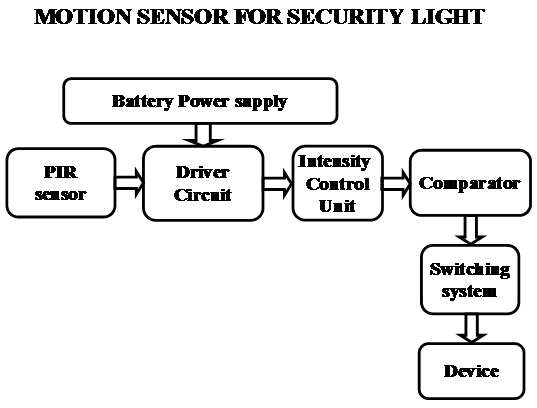
Motion Sensor for Security Light

The Motion Sensor for Security Light system uses Passive infrared sensor. These sensors are capable of sensing the presence of human being and post the same to the comparator IC. Now the micro comparator takes the responsibility of processing and judges the status of individual appliances and there by controls them using switches like relay, TRIAC.

The most important thing to be noticed here is the system is aimed for industrial, home, firm needs. So, there may be very high voltage devices like ACs and very low voltage devices like High intensity LEDS. Due to the presence of different appliances of different power ratings the design of the interfacing circuit should be done with utmost care.

Features:

1. Controlling the status of different electrical appliances
2. Live detection of human presence.
3. Low power consumption.
4. Reliable for industrial and domestic needs
5. High sensitivity.

The project focuses on the following areas:

1. Characteristics of PIR sensor.
2. High voltage device controlling.
3. Intensity controlling technique.
4. Embedded C program.
5. PCB design.

The major building blocks of this project are:

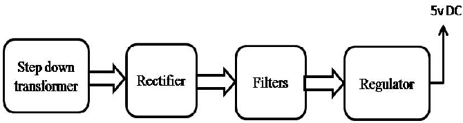
1. Regulated power supply with voltage regulator.
2. Micro controller.
3. Passive Infra Red Sensor (PIR).
4. Industrial appliances.
5. TRAIC boards.

Regulated power supply:

Block diagram:

Student college simultaneous alert to parent and HOD using GSM, RFID and RF

Aim:  The main objective of this Student college simultaneous alert to parent and HOD project is used to send a message after his son/daughter attended for the college and also the same acknowledge will go to the authority and incrimination of attendance every day.

Description :

This main motto of this Student college simultaneous alert to parent and HOD project is very much longer useful in colleges and also to the parents of the students. The idea behind this project is

1. identification of the student entry at the college in remote LCD display
2. Sending SMS to the parents of their sun/daughter entry at the college
3. Incrimination of the attendance details
4. Showing the student marks on the display by using RFID technology along with their password.

In this Student college simultaneous alert to parent and HOD project we will use 3 ACCESS cards for three students and executes the above points sequentially. The RFID reader which we are going to use for this project uses 125 KHz of frequency. Here in this project we will use total 3 wireless communications 1.GSM , 2. Radio Frequency, and 3. RFID

SOFTWARE : Embedded ‘C’
TOOLS : RIDE/KEIL to write code, ISP to burn the chip.
TARGET DEVICE : At89s52 based our own developed board.
ADVANTAGES : Low cost, automated operation, Low Power consumption.


BLOCK DIAGRAM :

Hardware : AT89s52
RFID reader
Max232
LCD
RF modules
GSM
EEPROM

location based temperature and humidity record system based on ZigBee and GPS

Aim: Aim of this project is location based temperature and humidity record system by using dual wireless technology.

Description : The present temperature and humidity record system project deal with ZIGBEE, GPS and hsm-20g sensors. Whenever he falls from the bed automatically coordinates of the bed will be sent to the caring people via ZIGBEE.

This temperature and humidity record system project main concentration is maintaining a record for temp and humidity for different different locations. We will store the envirement values in EEPROM along with the area fleet. These values will be sent to the authority using ZIGBEE technology.

SOFTWARE : Embedded ‘C’
TOOLS : RIDE/KEIL to write code, ISP to burn the chip.
TARGET DEVICE : At89s52 based our own developed board.
ADVANTAGES : Low cost, automated operation, Low Power consumption.

BLOCK DIAGRAM :


Hardware : AT89s52
ZIGBEE module
Max232
HSM-20g
Mux

Speech Recognition Controlled Intelligent Robot

ABSTRACT 

Aim: aim of this Speech Recognition Controlled Intelligent Robot project is moving a robot by giving specific voice to the module.

Description :

This Speech Recognition Controlled Intelligent Robot paper proposes a robot motion authored using speech recognition module. The proposed method is a user friendly method that easily authors  robot motion according to the user voice.

Robot is only possible to move when  the recorded voice is again repeated. we can give voice for robot like ‘Run’, ‘Stop’, ‘Left’, and ’Right’.

BLOCK DIAGRAM : 

Hardware : AT89s52
L293d
Robot plaform
Speech recognition module

SOFTWARE : Embedded ‘C’
TOOLS : RIDE to write code, ISP to burn the chip.
TARGET DEVICE : At89s52 based our own developed board.
ADVANTAGES : Low cost, automated operation, Low Power consumption.

GPS & RFID based Intelligent Guided Vehicle

AIM: The main objective of this GPS & RFID based Intelligent Guided Vehicle project is to develop an embedded system, which is used to find the location of a vehicle using rfid technology.

IMPLEMENTATION:

This GPS & RFID based Intelligent Guided Vehicle project is developed 8051 based At89s52 board interfaced with GPS modem and LCD for displaying the data.

BLOCK DIAGRAM:

POWER SUPPLY:


DESCRIPTION:

This GPS & RFID based Intelligent Guided Vehicle project is useful to find the way, whether their are going in the correct way by using RFID and Gps.

People want to know about the way they want to travel. To look after such persons our embedded project is very much useful. At According to this project we will issue an RFID CARD to read the car number. In our premises we will keep a READER for that RFID CARD. That reader I attached with a microcontroller based board along with GPS modem.for tracking the location.

The GPS & RFID based Intelligent Guided Vehicle system uses a compact circuitry built around Flash version of AT89S52 microcontroller. Programs are developed in embedded C Programming Language. ISP is used to dump the code into the microcontroller.

SOFTWARE:

Embedded ‘C’
RIDE to write code
ISP to burn the chip

HARDWARE:

At89s52 based our own developed board
Power Supply
GPS modem
LCD
RFID READER

ADVANTAGES: Low cost, automated operation, Low Power consumption.


Network Desktop Manager Java Project

Network is to connect two or more computers together with the ability to communicate with each other. Networking is to link two or more computing devices together for the purpose of sharing data.

It provides design, programming, development and operational support for LANs, WANs and other networks. A local area network (LAN) is a group of computers and associated devices that share a common communications line or wireless link.

Desktop Manager can assess the configurations of desktops and determine if they have received the proper updates — a task that is helpful to ensure all desktops are operating properly and securely. Network Desktop Manager manages desktop icons, background image and media message on LAN.

It controls the Desktops within the network and keep desktops clean and tidy. It even allows to add own Media message (video, image or HTML) that can be displayed on the remote Desktops within the network.

Our proposed project is Network Desktop Manager which provides the complete control on the remote desktop. When ever the administrator wants to operate the remote system this application provides the requested host desktop to the administrator so that he/she can operate the remote system directly with the system desktop. It also provides some of the features like chatting, desktop locking, desktop sharing, and port scanning.

Modules :

1. Desktop Sharing

Administrator can directly access the remote system by sharing the requested system desktop. Desktop Sharing is a server application that allows to share current session with a user on another machine, who can use a client to view or even control the desktop. Desktop Sharing lets users call a remote computer to access its shared desktop and applications.With the Desktop sharing we can operate our office computer from our home or viceversa.

2. Desktop locking and unlocking

Desktop locking and unlocking is a utility provided by the Network Desktop Manager to lock and unlock the remote desk to prevent others from accessing the system.Desktop Lock is a computer security protection and access control software product, we can use it to lock computer to prevent people from accessing your private documents and resources. When the computer being locked by Desktop Lock, none can access your documents, browse your computer, or use programs on locked system.

3. Messaging

Administrator can communicate with the remote systems that are connected With in the local network administrator can communicate publicly or privately.

Messaging is nothing but passing data to and from applications over the network which makes the synchronisation of data simple. Messaging allows users across the network to exchange data in real time. Most commonly, these data consist of typed conversations, but the power of the system lies in its ability to pass other data as well. This could be in the form of audio or video or, as will be presented here, other text data that will allow the two chatting parties to retrieve the same data base record by sending a primary key or keys from one to the other.

4. IP Port Scanning

If administrator wants to know the information about how many ports are working on the specified system and what is the port number allotted for the service, how many ports are closed, and how many are open.IP Port Scanner allows for testing whether a remote computer is alive with UDP and testing whether a TCP port is being listened with two types CONNECTS and SYN. IP Port Scanner reverse lookup IP address into hostname and read responses from connected TCP Port.

Software Requirements:

Platform : JAVA using Swings

Computer Network Project

The purpose of this Computer Network-Project is to implement a simplified web system. The system consists of three programs, the DNS server program, the Web server program, and the client program. The client program consists of two parts, a browser simulator and a client program for system testing.

Domain Name Server

In Internet, packets are routed based on the 32-bit destination IP addresses. However, these numerical addresses are inconvenient for users and applications. Instead, hostnames that consist of strings separated by periods are used. Using hostnames instead of IP addresses has another advantage, namely, transparency. For example, a Web site IP address may change if a different company is hosting the content, but the hostname can remain the same. The translation of hostnames into IP addresses and vice versa is coordinated by the domain name system (DNS). DNS is a hierarchical name space that can be represented by a tree (see the following Figure). The root of the tree is an unnamed node. The first layer of the tree contains the top-level domains. The second-level domain names are given to individual

companies, institutions, and/or organizations. Various levels of subdomains further divide a domain. DNS is a distributed database that consists of a hierarchical set of DNS servers. More specifically, there is a DNS server associated with each node at the root, top-level, and second-level domains. The DNS servers for the second-level domains serve both

iterative and recursive DNS requests. For example, a client in local domain may query its local DNS server (say S) for a hostname “www.yahoo.com” using a recursive request. S will search its cache (not the mapping table) for a match. If such match does not exist, then it sends a query to the root DNS server to get the IP address of the DNS of the “com” domain. Then S queries “com” domain DNS to get the IP address of the DNS of the “yahoo.com” domain. Finally, S queries the “yahoo.com” domain DNS to get the IP address of “www.yahoo.com”. After getting the mapping, S adds the entry to its cache for future accesses. Actually, if S already has a cached entry for “com” domain DNS server, then there is no need to go to the root DNS server.

Web System

In the Web system, a client (browser) sends a Web access request to a Web server to access a web page. The Web server, in turn, receives the request, parses it to identify the file to be accessed, and transfers the file to the client (or sends back an error message if the request is not correct or the file it accesses does not exist). A Web access request is specified by a URL and HTTP protocol is used for the handshake between the client and the server. A URL consists of two parts, a host name and a file name. The host name is the name of the Web server and the file name is the Web page to be accessed. When a browser gets a URL, it separates the URL into host name and file name. It sends the host name to DNS server to obtain the corresponding IP address of the Web server. Then, it sends the file name to the

Web server with the IP address returned from the DNS server. Subsequently, it receives the response from the Web server and displays the returned content or error message.

In an older version of a web server program, a TCP connection is opened to accept the client connection requests. When a connection request is accepted, the server spawns a thread to receive the subsequent HTTP requests, process them, and send back the responses. This approach incurs high overhead for thread creation and disposal. Thus, new Web server programs use thread pools to handle client requests. A thread pool consists of multiple threads that are created up front. When a user requests for connection, an idle thread is chosen to establish the connection with the user and process subsequent requests. The

number of threads in the thread pool can expand and shrink, depending on the load of the system. For a Web site with high hit rate, one Web server may not be sufficient to handle all the client accesses. Multiple Web Servers are frequently used to share the load. However, a mechanism is needed to allow the client to transparently connect to the web server with low load. In other words, the same URL should be used for the access no matter whether the Web server is replicated. There are several methods that are commonly used for Web server load sharing. Here we introduce the DNS-based load sharing. The DNS server is used to direct the client to different Web servers. In this approach, the DNS server can map one hostname to multiple IP addresses, where each IP corresponds to one of the replicated Web servers. DNS

server can use round robin policy to select the IP address to return to the client. Some DNS servers can probe the servers to obtain server load information and, based on the load information, selects an appropriate IP address to return to the client.

Tasks

  • The client program simulates a browser.
  • repeat
  • read in a URL;
  • get the hostname h and file name f from r;
  • if h is not the same as the hostname of the previous request then
  • send a message to close the previous connection;
  • send a query to its local DNS server to get the IP address for h;
  • establish a connection to h;
  • endif;
  • send a request to h to get file f;
  • print the file f;
  • until being killed; 

Your client program should provide a browser-like interface. The interface should allow users to input the URL r from standard input. Each input line consists of a URL and a sleep time. To simplify the parsing process, we define fixed formats for hostnames and file names. We assume that each hostname always consists of 3 segments separated by periods, the name of the host, the second-level domain name, and the top-level domain name. The host name and the second-level and top-level domain names are strings of 3 letters. We also assume a flat file system, i.e., no directories. Each file name contains only a string of 4 letters followed by “.htm” extension. The entire URL, thus, is a string of 20 characters. After receiving

the requested file, the client program (browser) should display the HTML file (similar to a browser). The client program may send multiple requests along the same connection if consecutive requests are for the same host (e.g., fetching multiple objects in a web page). When a request needs to be sent to a different host, then the client should send a closing message to close the connection established with the previous host. The message formats for the DNS requests and the Web requests will be discussed in the later sections.

Your client program needs to know the IP address and port number of its local DNS server. These are given in an input file which will be discussed in the next subsection. 

The basic DNS server simply receives DNS queries from clients, performs name resolution, and responds to the clients. You need to implement the DNS servers to process DNS requests. In your implementation, you only need to consider mapping hostnames to IP addresses, not vise versa. Though actual DNS has a fixed port number, we will have to use different port numbers for different DNSs so that multiple DNSs can be simulated by one single processor. Thus, the mapping should include port number as well. Also, we only consider three levels in the domain hierarchy, including the root, top level, and second level. A mapping table should be maintained for all DNS servers in order to process iterative DNS requests. For the second-level domain DNS, you need to also maintain a cache for name resolution for recursive DNS

queries. UDP protocol should be used for DNS communication. Each DNS server creates a UDP socket to receive requests from clients and another UDP socket to send responses to clients. Each DNS request contains the full host/domain name string. The string should contain 11 bytes. We add a blank at the end to pad the string to 12 bytes. Thus, the request message is of 12 characters. The DNS server at different levels simply extracts the partial string that represents the domain name it can serve and finds the mapping. Each

DNS response contains 4 fields:

  1. <host/domain name (12 bytes)>
  2. <DNS level (4 bytes)>
  3. <IP address (16 bytes)>
  4. <port number (8 bytes)>

The DNS level specifies the level of the DNS in the hierarchy the response is from. It contains 4 characters, the first 3 characters are blanks and the 4th character is the actual level, where 0 represents the root level, 1 represents the top level, and 2 represents the second level. The IP address will always be a 16 byte character string. If the actual IP address string is shorter than 16 characters, the remaining bytes are filled by blanks. The port number and is converted to text format with he corresponding sizes. In total, each DNS response, no matter which level it is from, should contain 52 characters.

We use thread pool concept to implement the Web server program. When a Web server starts, it creates N threads. Then the server listens to a TCP port. When a connection request comes, the server selects an idle thread from the thread pool and let the selected thread accept the connection and process the requests. Since the load of the system changes, the thread pool size should adapt accordingly. We create another thread to perform thread pool maintenance.

The request message from the client contains the client id (4 characters, converted from the integer value) followed by a file name. As discussed previously, the file name is a string of 8 characters, including 4 letters and the “.htm” extension. Overall, each web server request contains 12 characters.

At the Web server site, the Web files are located in one directory. The directory name will be discussed later. When the Web server receives a request message containing the file name, it appends the directory name and fetches the corresponding file. It then sends the file content through the same connection to the client. The response message starts with the file size and followed by the file content. The file size is an integer in text representation and it uses 12 bytes. If the file does not exist, then the value in the response should be all 0’s, indicating an error. The connection from the client does not close till the client close the connection.

Location Tracking Android Project

In this Location Tracking project we will track the location of the mobile user automatically when the message sent is matched with the code that is set by the developer in the application. If not it will be as a normal message to the mobile and will be stored in inbox.

This application can automatically run in background once it is installed until it is uninstalled. Here in this project we set a code which is itself a password and this code must be sent in the form of message from another mobile. This application can be installed in any android mobiles.

It is a project that you can able to find the location of a mobile which is been lost or missed. Our application can be very useful to the user because it is the only application that can trace the exact location of the mobile.

Our application must be installed in the mobile whose location is to be traced and in our application a code is been set. When our mobile is lost or missed we send a message with code to the lost mobile from another mobile, the application on receiving the message checks whether it matches with the code. If it matches then it sends a message containing the location to the sender’s mobile number.

This application works in background and the user cannot find this application on the mobile screen though it is installed in that mobile.This application will be supported by all the network providers.

This application makes use of GPS services and internet services in the mobile. For developing this application, we use components like broadcast receiver(), service() ,etc.

Existing system limitations:

The current system has no application to track the location of the mobile through an SMS. In the previous projects the message sent will be sent as a normal message to the other mobile .

But there is no application developed for location tracking automatically by receiving a predefined message without the user’s permission.

Proposed system with features:

In this project we are proposing a new form of messaging to get the location back as a reply automatically. In this project we will send a Message to my mobile, it will authenticate the message and reply the location if code is matched.

The main feature of the proposed system is, we are developing an application in such a way that it tracks the exact location of a mobile. For this application we are using features like broadcast receiver (), service (), etc.

This application makes use of internet services, GPS services in the mobile and based on this services it gets the location and sends it to the message sender’s phone number.

Our application can be very useful to the user because it is the only application that can trace the exact location of the mobile. Our application must be installed in the mobile whose location is to be traced and in our application a code is been set.

When the mobile is lost or missed we send an message, the application on receiving the message checks whether it matches with the password.

If it matches then it sends a message containing the location to the sender’s mobile number. This application works in background and the user cannot find this application on the mobile screen though it is installed in that mobile.

Generally in android market you will not get any applications that can find the location of the lost mobile by sending an SMS.

Finally we are proposing a new technology to find the location and according to the user flexibility named “Location tracking”.