VHDL Mini Project on Flappy Bird Game Code & Report

Specifications :

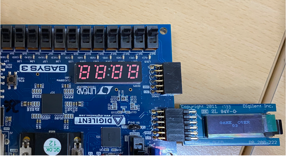
In our Flappy Bird mini-project, we were required to implement a game functionally equivalent to “Flappy Bird” using a Basys3 Board and a 128×32 pixel monochromatic Pmod OLED. Flappy Bird is a game where a ‘flying bird’ encounters obstacles in the form of vertical pipes. The objective of the Flappy Bird mini-project game is to guide the bird through the gaps in the pipes without touching them. The game is over if the aforementioned event happens. The bird changes its vertical position through a user-controlled switch and continuously flies to the right through a set of pipes. Collision detection is carried out using the known positions of the bird and the pipes.

Assumptions :

In our version of the game, the bird’s position is not horizontally fixed but moves to the right instead of the pipes moving to the left towards the bird. On reaching the end of the screen it re-enters through the left in the same level as it exists. Also, unlike the original, where pipes have an upper and lower half with a random gap between them, we have pipes either covering the upper half of the display or the lower half of the display. So we have allowed the bird to move only in two levels using a switch.

Design :

In this project, we have 4 pipes, two on the top and two at the bottom, the bird is represented by a symbol. The game has 9 levels with the game speed increasing after each level. The game also has an ‘enable’ and a ‘reset’ switch. The ‘enable’ switch is used to start the game and the ‘reset’ is used to reset the whole display and game. There is also a ‘jump’ switch which when ‘1’ places the bird in the upper half and when ‘0’ places it in the lower half. The top left corner of the screen displays the scores for the current level and the top right corner shows the current level.

Also, the score increases by one unit when the bird moves right by one unit. When the bird reaches the end of the screen the level is incremented and there is a transition screen showing the next level and the bird reaches the start of the screen. Whenever there is a collision the screen transitions to a display and shows the game over and score in that level. Once all 9 levels are crossed the screen shows that you won.

Description of files :

1. Delay: This component is used the deploy a delay of a given amount of time.
2. SPI_interface: This is used to read data bit-by-bit and send it to the display. An 8-bit input is passed into the module and it transmits it bit-by-bit.
3. OLEDInit: This module contains all the commands to turn on the display and this has to do every time the display is powered on.
4. BirdDisp: This is the main module in which the movement of the bird is coordinated and the output for the display is determined. A set of multiple screens has been defined here which is used to display the output on the screen of the Pmod OLED. Also, the scoring and level increment part is taken care of here itself.
5. Pmod_driver: As the name suggests this module works just as a driver for all the previously defined sets of modules.
6. charlie: This is the memory module and we have imported it for use in our game.

References :

• http://www.pld.ttu.ee/~alsu/04_I2C_RTC.pdf
• https://github.com/mmattioli/ZedBoard-OLED/blob/master/rtl/ascii_rom.vhd

Testing and Results :

In this, we were able to successfully create a functional flappy bird game, with nine different levels of speed. The game used switches to change the position of the bird as can be seen on the monochromatic OLED screen. When the bird reaches the end of the screen, it reaches back to the initial column again. When the collision takes place, the game over message is displayed on the monochromatic OLED, denoting the end of the game. Our demo showed that our game played properly with no signs of bugs, glitches, or failure while maintaining a visually appealing image throughout.

Download the Complete VHDL Flappy Bird mini project code, Report and output video file.

IL Processor on FPGA Platform Project for ECE Students

Design & Implementation of Instruction List IL Processor on FPGA Platform Project Abstract:

PLC (Programmable Logic Controller) issued in Industrial process-control applications. PLC contains a CPU core surrounded by memory and I/O peripheral devices. Most of the commercial PLCs available in market uses general purpose processor as PLC CPU. The general purpose CPU is not suitable for PLC in terms of cost and speed. This project proposes an Instruction List (IL) processor compatible with IEC 61131-3 standards. Instruction List isa simple textual programming method for programming of PLC, given by International Electro-Techno Commission As the program of PLC becomes more complex, the execution time taken by the PLC also increases resulting in failure in responding to high speed safety critical logic.

In conventional PLC’s the control specification first converted into instruction set listing that the operating systems can understand. Now a days it is becoming a standard practice to include safety critical function and operation control functions with single ladder diagram programming. Because of this, rungs in the ladder diagram increases and ultimately its performance in terms of speed decreases. For high speed safety critical application the execution time becomes critical. In this project, a 3-stage pipeline is proposed so that each instruction is executed in single processor machine cycle, providing high execution speed required in many high speed safety critical applications.

IL Processor FPGA Project for Final Year ECE Students

Problem definition:

Programmable Logic Controllers are widely used in the industrial automation applications. Now-a-days it is a standard practice to include safety critical functions in PLC programming. Also, MEMS based sensors are used in the PLC applications which gives input to the PLC which is very fast changing. The processors used as PLC core are mostly general purpose processors which fail to perform when very high speed of execution is required.

It is desired that processors should be dedicated to PLC tasks, rather than being general purpose and it should employ some technique such as instruction pipelining so as to speed-up the execution of PLC program. Also, the overhead routines should be less in the PLC operations. When this is achieved, PLC can respond to very fast changing inputs. Hence, to achieve fast response from the PLC, it is proposed to design a PLC dedicated Instruction List (IL) processor.

Implementation of Telemetry Link on FPGA

Main Project Title            :     Implementation of Telemetry Link on FPGA        

Project Description: The main objective of the Implementation of Telemetry Link on FPGA Project is to develop the Telemetry link Transmitter and Receiver on FPGA. In this Final Year ECE Project object’s measured characteristics or parameters are transmitted to a distance station where they are displayed on the screen, recorded and analyzed. In this electronics application transmitter section and receiver section has implemented on FPGA using Very High Speed Integrated Circuit Hardware Description Language (VHDL). The ModelSim simulator is used to simulate the design and Xilinx synthesis tool is used to synthesize the design on FPGA

VHDL Projects for Final Year Students

This category consists of list of vhdl projects with source code and project report and latest vhdl project ideas for final year students. Here you can download VHDL projects for free of cost. VHDL is one of the fast growing technology which is used for design circuit diagrams and test through software application.


FPGA implementation of 32-bit CRC Project

  •   Project Title      : FPGA implementation of 32-bit CRC Project
  •   Platform            : VLSI
  •   Language used: VHDL
  •   Software’s used: Modelsim 6.1f, Xilinx ISE 9.2i

  Project Description:

                           FPGA implementation of 32-bit CRC Project deals with error detection in digital data transfer applications. We are going to use CRC for error detection. The Philip Koopman’s polynomial is used for CRC generation, which provides two more bits of error detection capability. In this Electronics & Communication Engineering Project, at the transmitter check bits are appended (codeword) to the data to be transmitted on the network or channel. These check bits are generated by dividing the message polynomial with the generator polynomial. At the receiver section same operation is performed, if the remainder is zero the transmission is error free, otherwise error has been occurred. In this project we are using VHDL for designing the 32- bit CRC. Synthesis, Place & Route are carried out using Xilinx Spartan-3E kit for programming and for verification of the functionality.

Train Collision Using MIWI Communication.

Description: In this project we are going to prevent the train collision using MIWI communication. In this project we use sensors and micro controller and p2p protocol for communication. Code is written in C language and updated to micro controller which is the heart of the system for taking decisions.

 Hardware and software requirements:

Programing Languages            :   C, MASM, VHDL, MATLAB

Operating system                      :  WINDOWS XP

download Train Collision Using MIWI communication.

Implementation of Data Link Layer of Controller Area Network Using VHDL Project Abstract

Data Link Layer of Controller area Network Project Description: 

                    The scope of Implementation of Data Link Layer of Controller area Network using VHDL Project  is There are many protocols which are developed for Serial Communication.But these protocols lack the real time capabilities.As a subject of real time capabilities Controller Area network was developed.

 The Data Link Layer Of controller area network has the following features:

  •     Serial,multi-master Communication protocol.
  •     Prioritization of Channels.
  •     Error detection.
  •     Framing of the outgoing messages.
  •     De-framing of received messages.
  •     High levels of data integrity and data rates upto 1 mbit/s. 

This project is implemented Using Xilinx and ModelSim simulator.

download Implementation of Data Link Layer of Controller area Network using VHDL Project Reference document.

Asic Implementation of DDR SDRAM Memory Controller Using VHDL Project

DDR SDRAM Project ABSTRACT:

Asic Implementation of DDR SDRAM Memory Controller Using VHDL is advanced version of regular SDRAM which is developed with advanced features like effective bandwidth of memory and able to transfer data on both edges of clock cycle. DDR SDRAM is mostly used in computer applications like laptops, networking, DSP processing systems….etc. In present electronic systems cost and speed is important factor, DDR SDRAM will reach present standards more importantly in the field of digital signal processing where memory speed is key factor.

This project is implemented using Xilinx and ModelSim Simulator.

download Asic Implementation of DDR SDRAM Memory Controller Using VHDL project reference documents.