Simulation Procedure
Introduction:
The previous chapter describes the design of the simulation and this chapter concentrates on the explanation of the corresponding simulation process that is implemented in the project. The explanation of the process that is followed to create the scenarios that are required for the simulation is done step by step in this chapter in addition with the other procedures like network configuration, configuration of nodes, configuration of wireless LAN server, setting profile config, application config, mobile config and setting the DES metrics. All these explanations are done to provide a better understanding about the simulation procedure for achieving the aim of project, the respective screen shots are also appended in the sections below. As discussed earlier the simulation of this particular application considers two scenarios and the process involved in creating both the scenarios and the process involved in simulating the scenarios in order to obtain the results is explained clearly in the further sections of this project.
Simulation process of first scenario:
The design chapter of this document already explains about the requirements for the simulation of scenarios, in this scenario the network selected for the simulation is the Mobile Adhoc Network and the sensor nodes needed are selected as the mobile nodes. The number of mobile nodes used for the simulation is taken as 10 and a wireless LAN server is selected as the server which can behave as a sink node and the general settings that are required to forma a required network are as follows:
Simulation process of basic network:
The basic network selected for the simulation of this project is “Mobile Adhoc Network and this section explain the process that is implemented to create a network and to make the basic settings for the network as required. Based on the requirement of the user a new scenario is deployed and renamed as the initial step of the simulation procedure. The steps involved in creating the scenario and the screenshots that explain the process involved is shown below:
- The file menu is selected by starting the OPNET modeler and new project is chosen.
- Based on the interest of the user the name of the project and name of the scenario is changed.
- In order to create a blank scenario “Create blank scenarios” option is selected
- MANET is selected as the network required for the simulation this is also set as the model family.
- Campus is selected as the network area required for the simulation
- 1000 X 1000 square meters is taken as the size of the network and therefore the creation of a fresh scale of network is done and when once all these settings are done, then the network is said to be prepared for using.
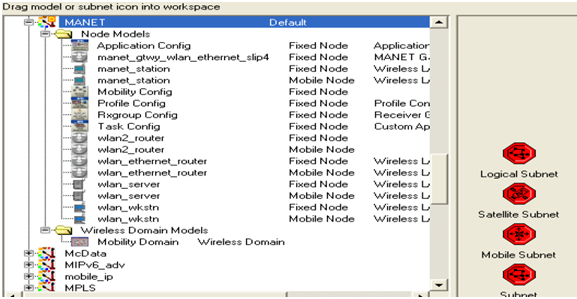
Once the creation of the basic network is done, at the user interface level the object palette is opened and then the operations needed are dragged from the object palette and dropped on the work space. The object palette that is opened in the simulation is shown using the screen shot given below the shown screen of the object palette also includes the objects that are needed for the simulation of the scenario.
There will be different kinds of nodes provided by the object palette shown above and these nodes ate selected for simulating process through the MANETs and the nodes selected are the process involved in the creation of the network is given below:
- From the opened object palette a fixed node that is a wireless LAN server is dragged on to the work space and this server will act as a sink node which can handle all the mobile nodes.
- 10 mobile nodes are selected and dragged on to the work space and these nodes behave as the sensor nodes that are needed.
- An application configuration node is used for forming the applications that are needed.
- A profile configuration node is used for the forming of the definitions of profiles.
- A mobile configuration node is used for providing mobility for the sensor nodes.
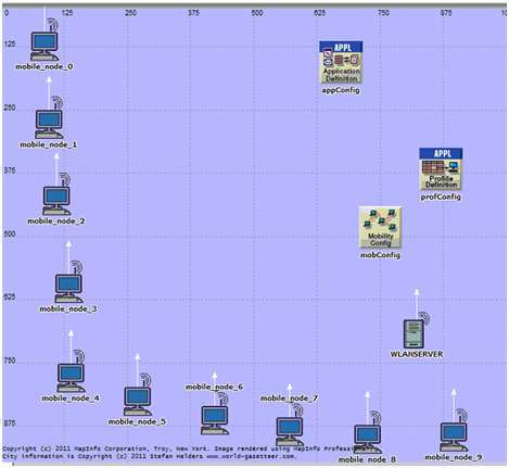
All these nodes listed above are dragged from the object palette and placed on the working station and the process of placing these nodes is very easy and very helpful in the creation of the network needed. The setup required for the basic network required for this particular scenario is represented in the screenshot given below and this contains all the required nodes listed above.
The nodes needed for the creation of the network are represented in the screenshot given above and the simulation process is set ready when once the network setup is done. The sections below explain the other steps involved in the simulation procedure.
Application definitions process
The above section explains the steps of simulation process involved in the demonstration of the network required for the project and here this section focuses on the settings of application configuration and definitions needed for the simulation of the scenario. The application needed for the simulation is defined by using the application configuration node as discussed in the previous chapter. In this particular scenario three applications are used for the generation of the traffic needed. The three applications used are the FTP, voice and video conferencing and these are used for the generation of TCP traffic across the MANET. This section explains the configuration of the application by creating the FTP, Voice and video conferencing as the applications. The steps given below are followed for the application configuration.
- The attributes of the application config can be edited by selecting the “Application configuration node” and then by giving right click on that and then by selecting the edit attribute option.
- While selecting the edit attribute option a window is popped out for processing the editing.
- Then the attributes required are added for the application
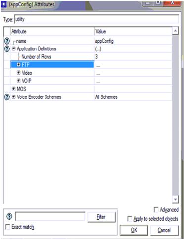
The following screen shot will represent the actual process of setting the application configuration.
The procedure that is used for editing attributes of the application configuration node is shown using the screenshot given above. As the number of applications used in this scenario are three the number of rows parameter is taken as three. Once it is taken as three, the application names should be added and for this separate section are used for entering the name of the applications as FTP, Voice and Video conferencing. After the name of the application is entered the definition of the applications are also entered by selecting the FTP, voice and video from the options available as indicated in the screenshot. At first the application is set to off and then it must be expanded for the application to be activated and it’s a known thing that various kinds of application loads are observed and in this particular scenario the medium load of application is selected for the simulation as viewed in the screen shot. The generation of traffic across the MANET is generated by the medium load of the application and once the required setting are invoked to the application configuration node is completed the setting for the profile configuration node must be done as the very next step and that is explained in the next section.
Profile definition process:
Setting the profile configuration is very much necessary for the simulation procedure in achieving the actual goal of the scenario particularly in generating the traffic across the MANET. The profile definitions and the additional settings must be added to the profile configuration node similar as the editing of application configuration node that is done in the above section. The process followed for making changes to the profile configuration node is explained step by step as follows:
- Edit attributes option is selected by selecting the profile configuration node placed in the work space and then by giving right click.
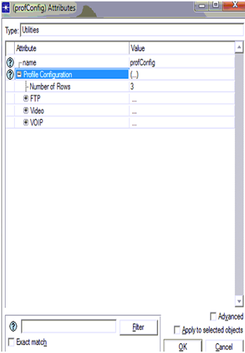
- Once this option of edit attributes is clicked a window gets popped out at the user interface and then the editing of attributes of profile config node is done according to the user requirement. In addition to this the definition of the profile is also appended and this is viewed with the screenshot given below:
This screen shot shows the definition of the profile configuration and the attributes required for the setting of profile configuration node. It is clearly shown in the screen that the number of rows attributes is selected as three. As we used three applications for the simulation of this particular scenario, the number of rows is also taken as three and the profiles must also be selected as three and they are the FTP, Voice and Video profiles. Once these profiles are set the definition of the profile must be added additionally. The profile configuration node has some other settings required to be done and all those are indicated in the screen shot shown already. The additional settings are the parameters required for the simulation of scenario and they are the start time is taken as a constant time values that is 10 seconds and the profile time duration is taken till the profile ends. Similar to the setting of application config, here also the profile configuration is inviked on the entire network when once the setting is completed and this is confirmed just by selecting ok button. Therefore when the settings of application and profile configuration are completed they are allocated to the wireless LAN server and nodes. As a next step to this setting, configuration of mobile nodes and server is done and that is explained in the section below.
Configuration process for mobile nodes and wireless LAN server
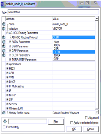
It is already discussed that simulation of this scenario across the MANET is done using 10 mobile nodes and a wireless LAN server, the general configuration of the mobile nodes and the server is explained in this section. This step of the simulation process is considered as the most important step in the project. In order to do the simulation of the scenario, all the 10 mobile nodes and the server must be assigned with a routing protocol, and in this particular project OLSR routing protocol is assigned for generating the traffic across the MANET. The process of applying the OLSR routing protocol for the nodes and server includes the following steps.
- The work station is opened and then all the 10 mobile nodes and the wireless LAN server are selected.
- Then by right clicking on any of the node, options are opened and from that the edit attributes option is selected.
- Then the user should select the set routing protocol option from the window opened specially for that node and then choose the required routing protocol in this particular project the OLSR routing protocol is selected
All this process is represented using a screen shot given below:
All the 10 mobile nodes and the wireless LAN server supports the OLSR routing protocol when it is applied to them and that process is shown in the above screenshot. During the selection of the routing protocol for all the nodes and the server there are various routing protocol available as options but only the OLSR routing protocol is selected in this application and once applying of the protocol is completed when once the apply button is selected. Once this process is completed IP addresses must be assigned for them as the next process and this is described in the following section.
IP address allocation Process
In This section briefs about the process to apply and to allocate the necessary IPaddress to each and every node and all the proceedings is given in step wise in this scenario is given below
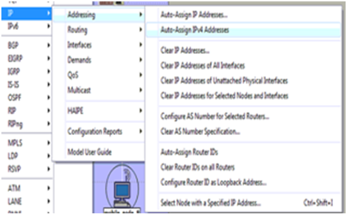
- We can access OPNET tool and though it we can enter to applications menu and there we can view the IP address option is given.
- Now from the IP option by using navigation steps where user can easily recognize some of the features before addresses are allocated to the LAN server and mobile nodes
- Then we select the option “auto assign IP4” addresses to allocate the concerned IP address to all the nodes existing in this network and the screenshot showing all the above details is specified below
The requirements needed at the work space are selected earlier they include mobile nodes and wireless LAN server and this can be observed once the application menu is unleashed .from the above screen we can make certain implementations such as we can open IP protocol menu the next step is to navigate into addressing option and the concerned address is allocated. We may also conclude that from the given screen shot that Auto assign IPv4 addresses option is chosen to allocate the necessary IP’s to all the mobility nodes and LAN server and from here the original settings for application purposes are applied for all the nodes that we come across and the server including the process applied is given in below scenario
Mobile nodes and wireless LAN server Application Settings
By making sure that entire network is ready for simulation purpose in the 10 mobile nodes and for this a wireless LAN server is required and it is configured for back up in the corresponding application and remaining profile configurations are common as discussed earlier.Here also two methods are there and both of them are given from step to step basis
- In the work space given select any one of the mobile nodes and any one of the node is randomly selected and it is modified by choosing its attributes and this can be inferred by right click on the particular node
- Once the option “edit attributes” is opted a window is pop up on the screen of the users in this windows both the application as well as profile settings can be configured
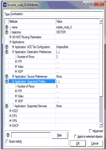
- The destination preferences ,profile tabs of these applications are navigated to set the necessary configuration and the screen shots resembling these settings are given below
From the above screen shot it is decided that the application destination preference tab is opened to fix the necessary application and the number of rows is fixed as 3 since three applications are developed for simulation process. Once the application is choose the required servers opted are FTP server, Video server, Voice sever as mentioned in the above screen shot once these settings are completed the actual application supported profiles choice is used to back up the ftp,voice,video profile is developed in the particular configuration time .as we decided to take 3 rows and ftp,voice,video is choose based on the profile configurations shown in the previous screen and these settings implicated to the opted objects and this can be viewed in screen shots given below once the mobile nodes are confirmed to back up the concerned application and its profile now the wireless LAN server is also fixed accordingly and this clearly described in the form of steps
- Go for the wireless LAN server and the options we automatically suggest is “edit attribute” and modify the desired application and profile characteristic.
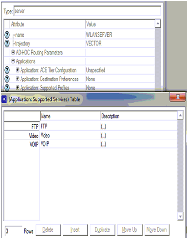
- At present explore the options so that application support services while new window is released to get in to the profile to be supported
- Append the rows to fix it 3rows simultaneously three profiles are developed in scenario can be viewed.
The assumptions can be made from the above screen that three rows can be created and simultaneously three server levels are chosen they are FTP, VOICE, VIDEO servers the necessary profiles to be backed are depends upon its description is fixed as viewed in above screen .Now go for OK button for continuously two times to imply these configurations to the wireless LAN server .As per the studies before the next process to modify these characteristics to help the deployment to be easy for application and the concern steps e valuate this process
- Expand the applications menu existing on the high end of the OPNET workspace.
- It can be noticed that vivid options at this scenario and now select the option and place it in the concerned choice and for this the screen is given below
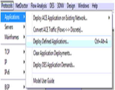
Protocols index is elaborated and from now the application selection is opened to do deliver the operations as shown in the up screen .from this image it is guaranteed that the installations applications option is opted for deploy to be done in the network and the next ultimate screen is seen to the users
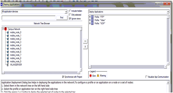
The definite exploitation process is given in the above screen and from this screen it can be noticed that all the mobility nodes are lagged towards the supply and the wireless LAN server is lagged around the terminal. The reliability of the installation process can also be verified with the button process reliability as given in below and from here the nodes and three servers to back the applications and the profiles developed across the simulation fixing the mobility to each and every nodes is the last place of the total settings and the equivalent process is shown
Mobility Process definition
The necessary requirements for developing mobility nodes is all fixed in the mobile nodes and this can be clearly viewed in the screen shots in the above section this is done by taking the mobile configuration settings. Mobile nodes can be described at this case and this corresponding process applied is also seen below.
- Choose the mobile config node and select the edit attributes choice by just click on the node.
- Ultimately a pop up window opens after this process and the necessary mobility can be fixed as it is fixed in the below screen
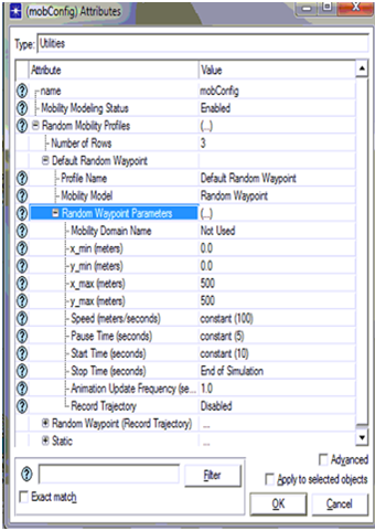
As we all can get idea after seeing the screen shot of choosing the mobility node in three different ways one among them is default random waypoint is selected and the required parameters are given in that particular scenario.Random waypoint parameters are fixed into the velocity of the mobile nodes is taken as 100 m/sec. And the pause time is fixed as 0 as shown in the fixed screen and from the screen it can be noticed that start time is defined to be a constant value of steady 10 seconds and the end time is till the conclusion of simulation. Once all these configurations are happened these are simultaneously applicable to all the mobile stuff and the genuine process segt here is given in the scenario below.
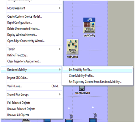
- Go to menu(TOPOLOGY)and select the choice random mobility
- As the no of options grow there is scope of setting the choice like fix random mobility and the next screen shot is given
From the screen we viewed it can be noticed that set mobility profile is utilized to fix the required mobile configurations to all the nodes on the system consisting network and this is surfed by the utilization of random mobility option and the original mobile settings is to fix all th configurations on the same network .Now the final lap in the simulation of this context is to fix the individual DES statistics and this procedure is given below.
Process to choose performance metrics
The necessity of performance metrics is required to evaluate the performances of the each independent context and also to distinguish the remaining scenarios developed in the simulation process and the original process given is in these scenarios
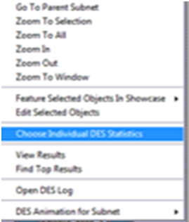
- “set the statistics” is the option choose by right clicking it on the wireless network scenarios
- Select the individual DES statistics is taken to set the abilities of the concerned metrics and the particular screen is given below
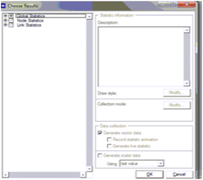
Once the choice is taken a pop up window is opened from there the necessary options are given around the capability analysis and the necessary screen is seen
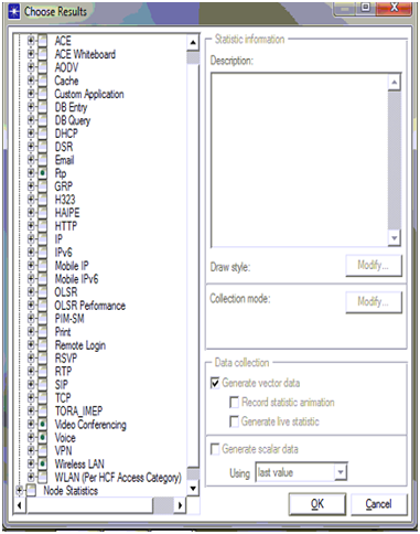
Hence by seeing the screen we can derive that there are three levels of metric performances and among the three global statistics are utilized in simulation process and the equivalent metrics is shown below.
As there are three applications in this project, following are the performance metrics used to evaluate the performance of the proposed secured wireless LAN configuration
FTP
Following are the performance metrics used for FTP application
- Traffic received in bytes per sec
- Traffic received in packets per sec
- Traffic sent in bytes per sec
- Traffic sent in packets per sec
Voice
Following are the performance metrics for Voice application
- Jitter
- MOS
- Packet end to end delay
- Traffic sent in byte per sec
Video
Following are the performance metrics used for video application
- Traffic sent in bytes per sec
WLAN
Following are the WLAN metrics used
- Delay
- Network load
- Medium Access delay
- Load
Simulation process of second scenario
This simulation model is similar to the first one which comes with some necessary changes and the only change in this process is choosing of LAN parameters in the scenario remaining is the exact replica of the first one and the screen shots give anew idea of this process. Once the necessary system is replicated the necessary configurations are also varied for all the mobility nodal and the wireless LANS server screen shots are given below.
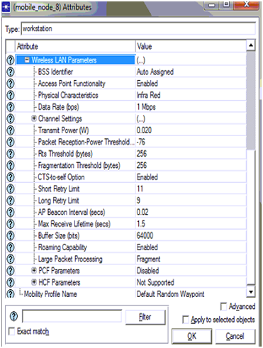
From the above screen shot we can conclude that few configuration settings are changed for the usage of wireless LAN characteristics of the above screen and the original settings in this scenario is changed listed below
- Transmit power is set to 0.020
- Packet reception power threshold is set to -76
- RTS threshold is set to 256
- Fragmentation threshold is set to 256
- CTS to self option is set to enabled
- Short retry limit is set to 11
- Long retry limit is set to 9
- AP Becon interval is set to 0.02 seconds
- Max receive life time is set to 1.2
- Buffer size is set to 64000
- Roaming capability is set to enabled
Large packet processing is set to fragment
Once both the scenarios are ready to work then the simulation is processed for 5 minutes to acquire the results and the corresponding results is taken the simulation run is described in brief in the future chapters.

