PROBLEM DEFINITION
This application is designed to develop a Placement Management system to assist the placement officer’s to maintain the student data and sort them according to the percentage criteria required for the company and student can review his/her data overcoming the drawbacks of the existing system.
OBJECTIVE
The purpose of this application is to develop an Application which facilitates the officer’s to maintain the student data and sort them according to the percentage and even delete the records and student can review his/her data overcoming the drawbacks of the existing system.

EXISTING SYSTEM
In the current scenario People Store the data of the students using some applications and sort them manually so filtering the people is a difficult task as there will be lots of students in the organization.
DRAWBACKS OF THE EXISTING SYSTEM
The major problem in the current system is that filtering the data is a manual approach and needs lots of time and a man can make mistakes while sorting.
PROPOSED SYSTEM
The application aims to overcome the drawbacks of the existing systems in the market and implement a few additional features.
The proposed systems consist of 2 different modules namely Admin and Student; each module has a different set of tasks to be done.
INTRODUCTION
The purpose of this application is to develop an Application which facilitates officials of the placements in the educational institutions to manage their student records. Using this Application Placement officer can add data of the students and even filter the students according to the criteria required for the organization and student can see his/her complete profile.
Functionalities
The product includes a few functionalities that help the admins to get the sorted list of students easily and effectively.
These functionalities include:
- Administrator Panel to add/review/sort/delete student records.
- Student Panel to review his/her data
MODULES
This application contains three modules.
- Admin Module
- Student Module.
MODULES DESCRIPTION
- ADMIN MODULE
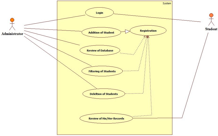
Admin Panel facilitates the officer’s to register a student, review the complete data, sort the data according to the percentages, and delete the data
Each Functionality is obtained by clicking the particular links
- STUDENT MODULE
The Student Module facilitates the student to review their own data by entering their roll number.
These are the Modules covered in this Application.
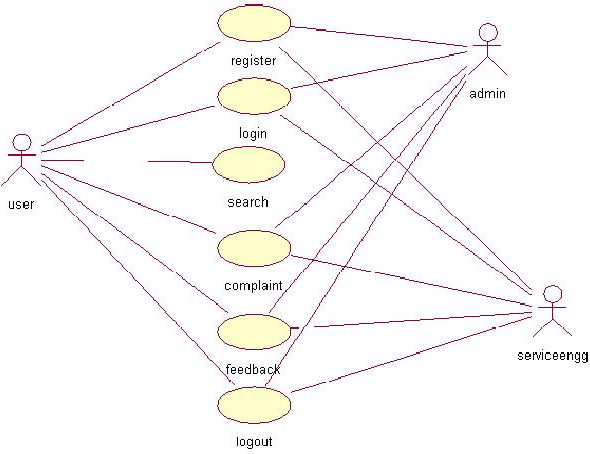
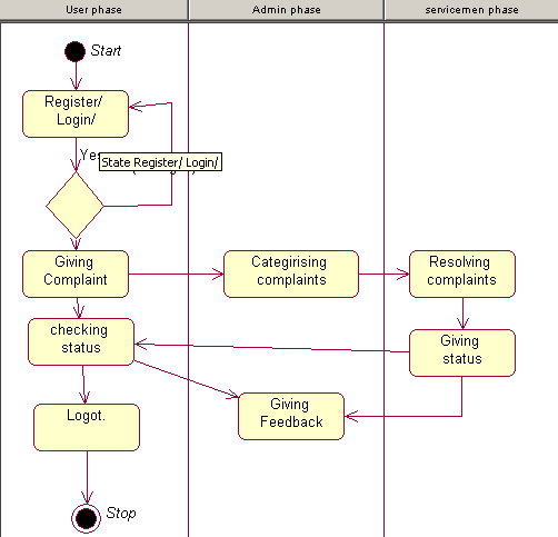
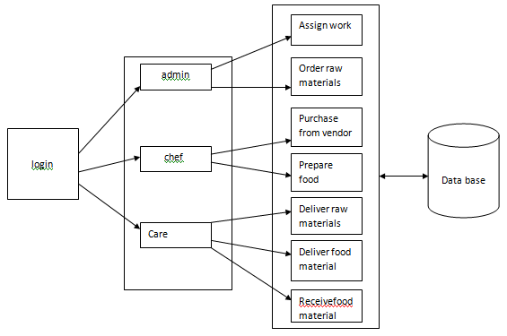
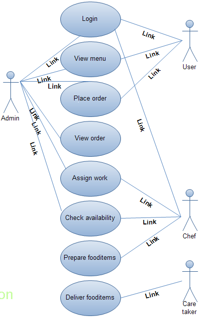
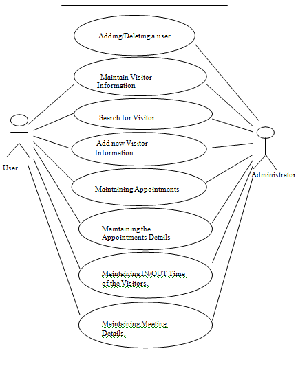
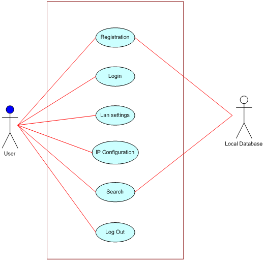
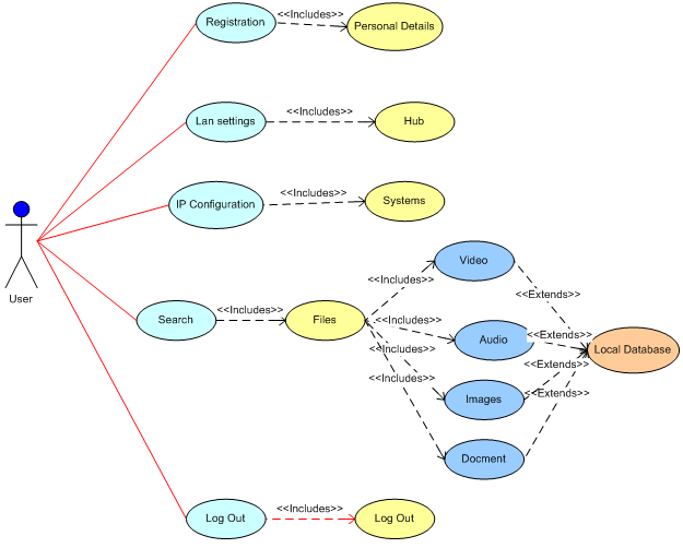
Use Case Diagram:
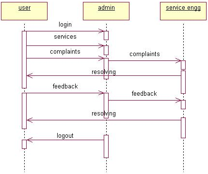
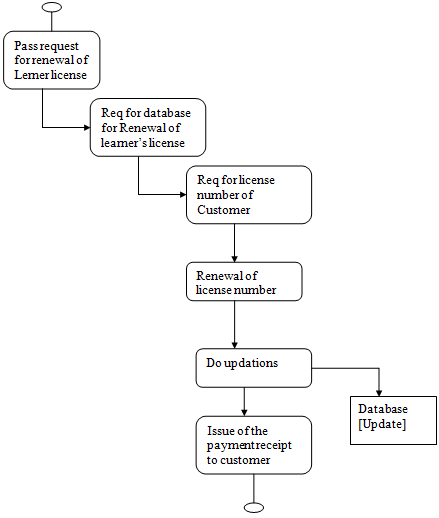
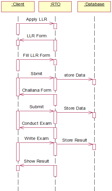
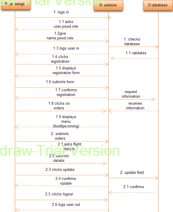
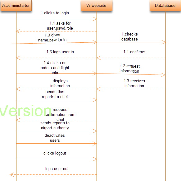
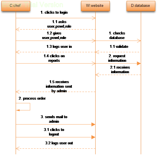
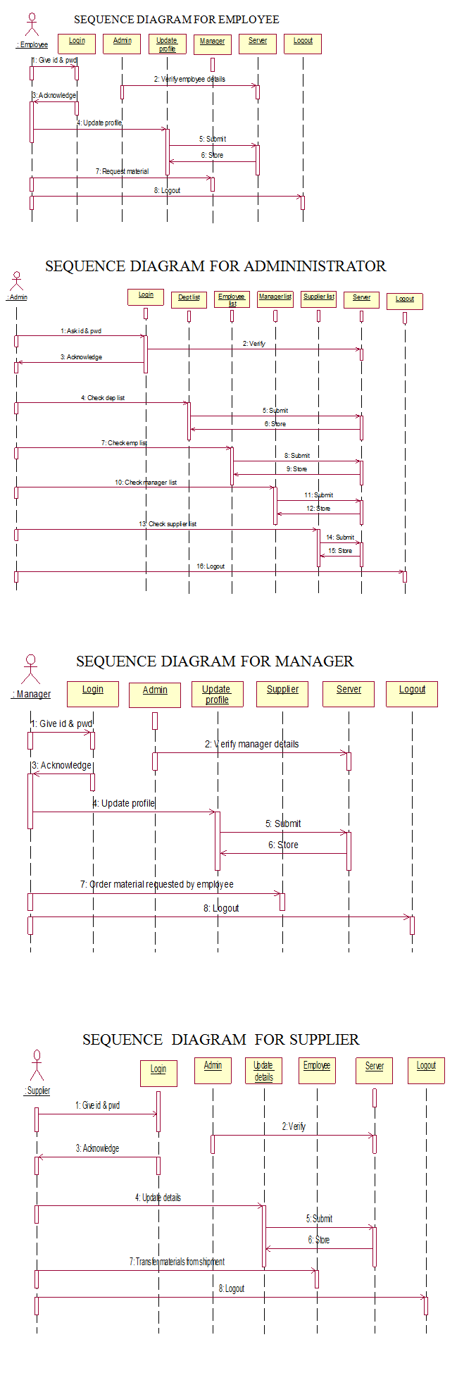
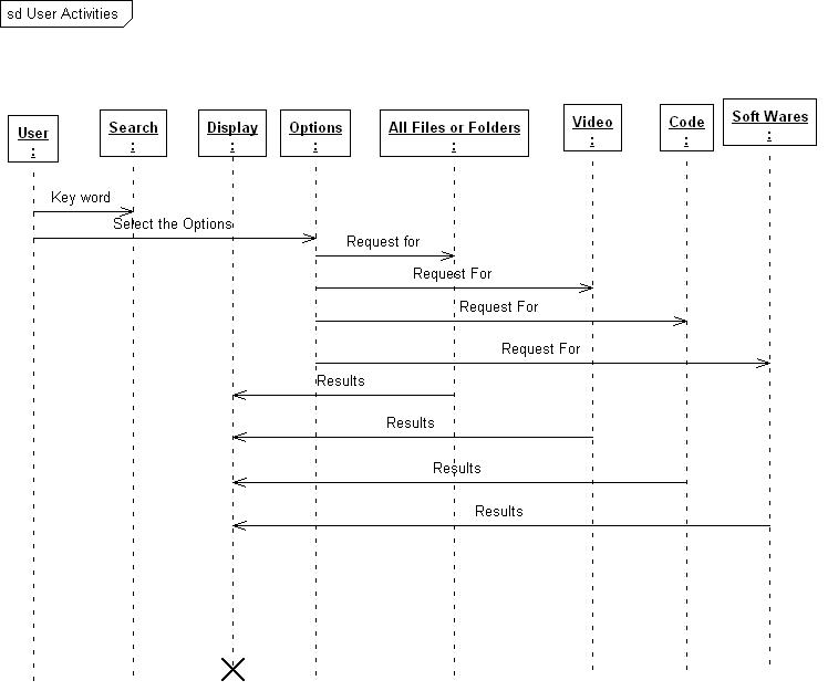
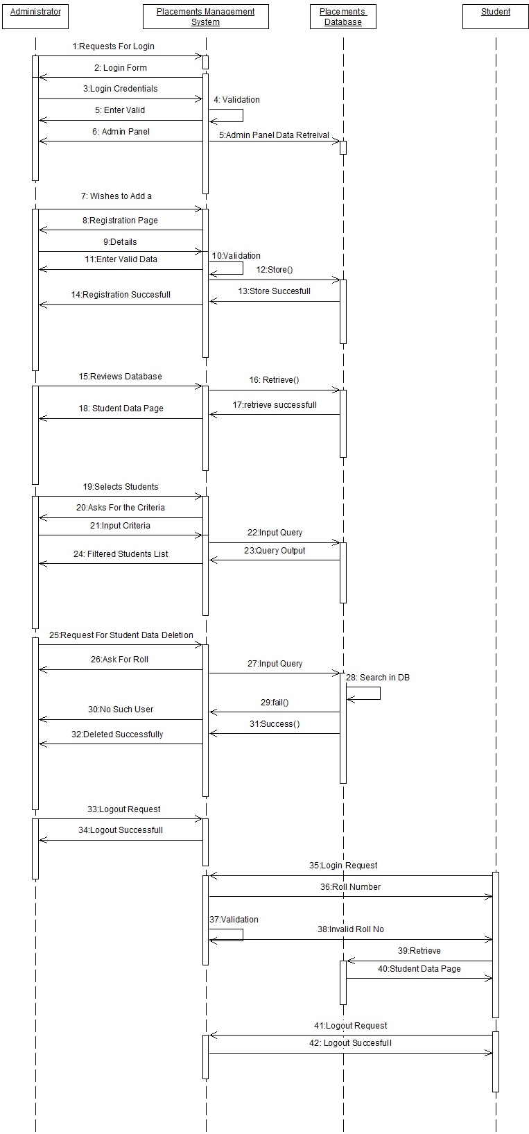
Sequence Diagram:
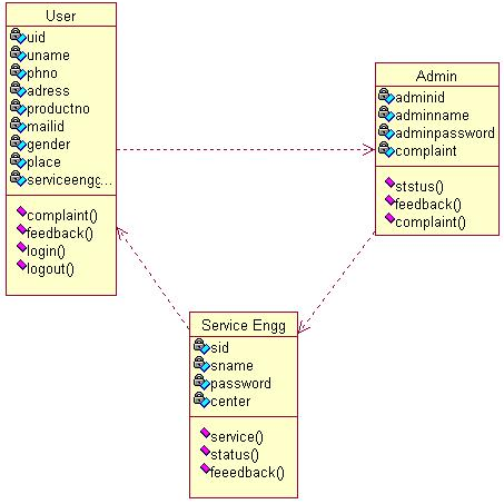
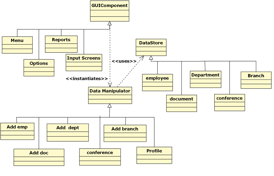
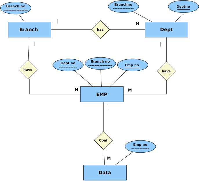
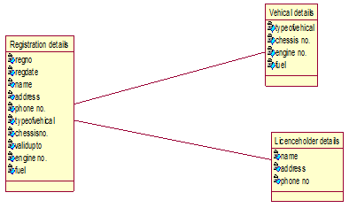
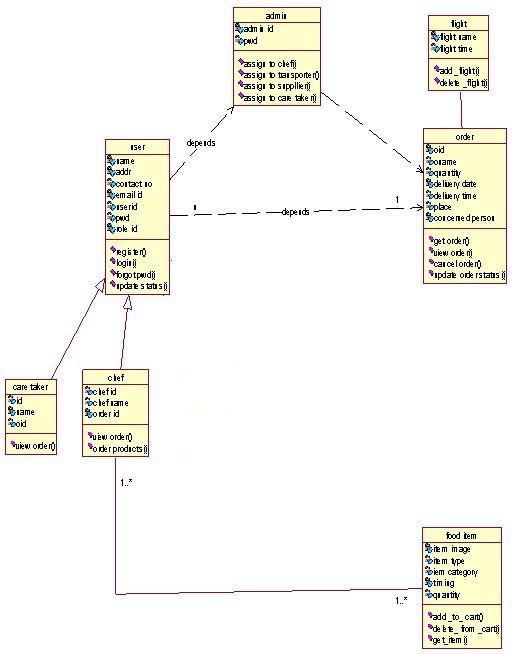
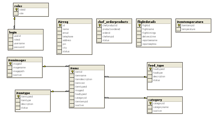
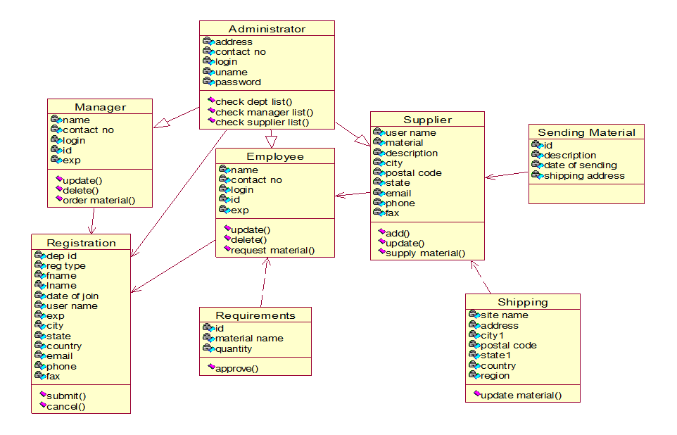
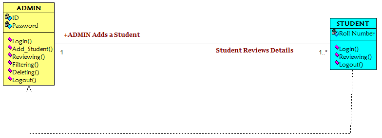
Class Diagram:
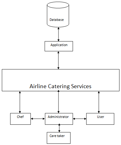
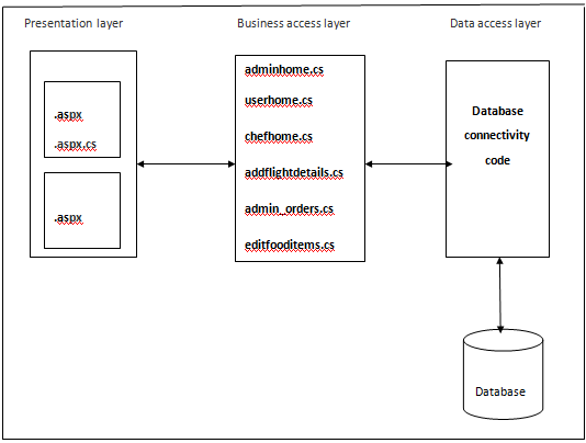
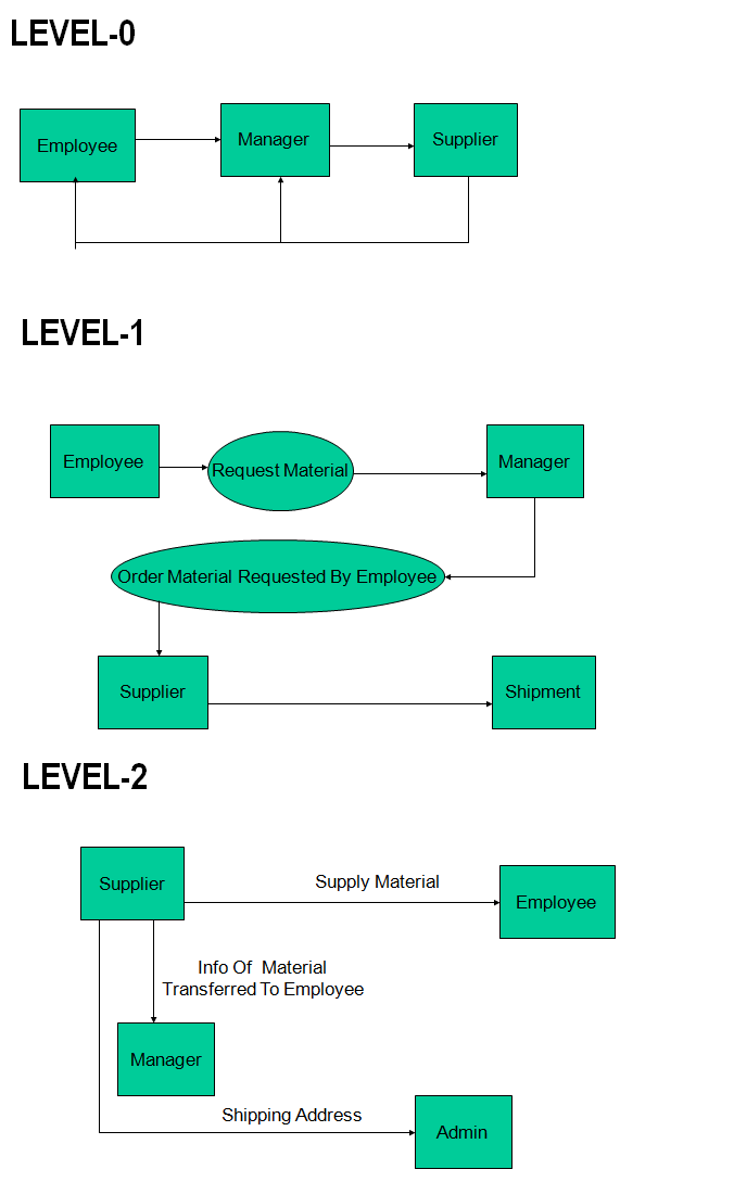
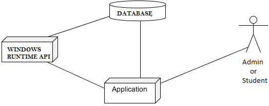
Architecture Diagram:

1) Test Case for Software Installation.
| Test Case ID: | 1 |
| Test Case Name | Software Installation Test |
| Purpose: | To check whether the required Software is installed on the systems |
| Input: | Run the Windows 8 SDK in Visual Studio. |
| Expected Result: | Should Display the Integrated Development Environment |
| Actual Result: | Displays the IDE for installing the Software |
| Failure | If the Software is not installed and configured accordingly then the system will not work |
| Remark | Success |
2) Test Case for Running Application.
| Test Case ID: | 2 |
| Test Case Name | Application Run Test. |
| Purpose: | To check whether the application runs on the local machine |
| Input: | Run the application |
| Expected Result: | Application should run on the local machine. |
| Actual Result: | Application is running |
| Failure | Could not run the Application (Force Closes). |
| Remark | Success |
3) Test Case for Selecting ADMIN.
| Admin Case ID: | 3 |
| Test Case Name | Choosing ADMIN Module. |
| Purpose: | To check whether the application chooses the selected module and loads pages accordingly. |
| Input: | Click on ADMIN link. |
| Expected Result: | The pages from ADMIN Module are loaded. |
| Actual Result: | The pages from ADMIN Module are loaded. |
| Failure | Module will not be loaded. |
| Remark | Success |
4) Test Case for Selecting STUDENT Module.
| Test Case ID: | 4 |
| Test Case Name | Starting a Student Module |
| Purpose: | To check whether the application loads the pages from the selected Module. |
| Input: | Click on STUDENT link. |
| Expected Result: | The pages from STUDENT Module are loaded. |
| Actual Result: | The pages from STUDENT Module are loaded. |
| Failure | The pages from STUDENT Module will not be loaded. |
| Remark | Success |
5) Test Case for Checking Database.
| Test Case ID: | 5 |
| Test Case Name | Testing the Database. |
| Purpose: | To check whether the application stores data according to security constraints. |
| Input: | Select ADMIN Module. |
| Expected Result: | Successful List of Registered STUDENTS. |
| Actual Result: | List of Registered STUDENTS. |
| Failure | Display POP-UP alerting NO DATA FOUND |
| Remark | Success |
6) Test Case for Viewing Data in student module.
| Test Case ID: | 6 |
| Test Case Name | Viewing Student Data |
| Purpose: | To check whether the application loads the student data according to Roll Number Entered by Student. |
| Input: | Roll Number |
| Expected Result: | Student Own Data is Loaded |
| Actual Result: | Student Own Data is Loaded |
| Failure | Student Own Data is not Loaded. |
| Remark | Success |
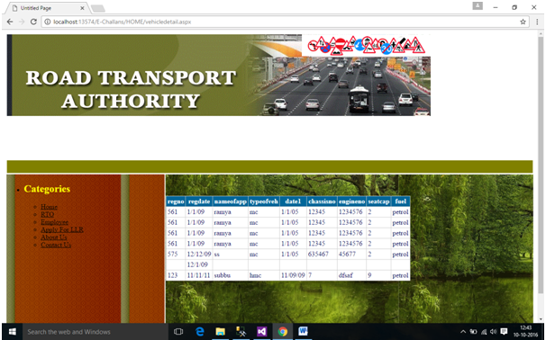
Output Screens:
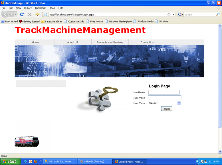
- Application Entry
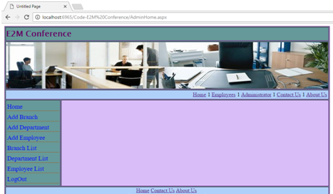
- Main Window Opened
- Admin Selected
- Popup for Complete Details
- Popup of Invalid Credentials
- Admin Module Entry
- Add a Student Clicked
- Popup of Successful Registration
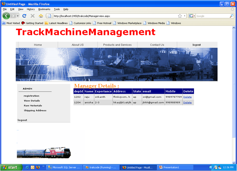
- Review Database clicked
- Select People Clicked
- Sorted People According to Percentage
- Delete Students Details Clicked
- Popup of Delete Result
- Admin Logout
- Student Clicked
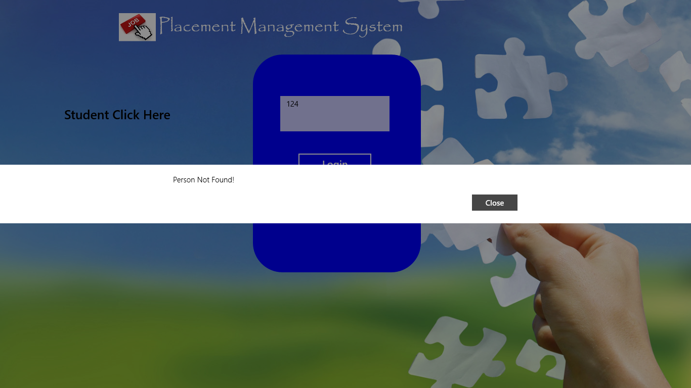
- Popup of Student Not Found
- Student Page Entry
- Student PageTo see Your Data Clicked
- Logout Clicked
Conclusion:
The end result will be an application that will help the TPO’S to manage the student data very efficiently. The officials can sort the data in time whenever there is an urgent requirement. Using this Application Placement officer can add data of the students and even filter the students according to the criteria required for the organization and student can see his/her complete profile.
APPLICATIONS AND FUTURE ENHANCEMENT
As the Requirements Changes day to day, we also need to give extensions to the application in the form of versions.
A few changes that can be expected in the future are:
- A student can request for updating his/her data to the officials
- Automatic deletion of record after the student is passed out from college
- Admin can approve a request from a student panel
- Admin can set Password Dynamically
Download Placement Management System C# with XAML Project Report Documentation.