PIC Micro controller Data Acquisition System Project Report

Introduction:

The debugging of an electrical circuit can be done by knowing the voltage , temperature and current information. By providing the data acquisition system in the power supply  we can know these values . this paper concentrates on developing a data acquition system which measures the voltage from 0 to 50v, current values up to 50 amps and finds temperature on the ambient and load.

Construction of data acquition system:

The current voltage and temperature sensors are used which gives the sensed information during the working of the circuit the sensed information from the sensors is fed to analog to digital converter, which is a 14 pin package. For monitoring the process a pic micro controller is used. From the available pic microcontroller’s we need to select the required one which has a 4adc channels and counter timer and quart. For the pic microcontroller to operate accordingly we have to provide it with the data. The internal oscillator frequency is set to 4mhz for its working. The baud rate at which the data is transmitted is 9 bits in which one bit  is used for stat or stop information and the other 8 bits are used for data information. To control the sampling rate timer is used and by polling the overflow bit are controlled. The micro chip on the pic microcontroller provides environment for compiling coding setting up and controlling programs. The flash memory of the pic can be reprogrammed by using the interface ide of usb. By using RS232 and max232 the transfer of digital data is possible in between the pc and thru registers of the microcontroller.

 Conclusions’ and Future scope:

Here the complexity of the project increases due to selection of the pic microcontroller other than a normal microcontroller. The data acquisition system can be further developed by the use of high resolution ADC converters. Here the chances of crashing occurs when the captured data is plotted on a excel sheet, which can be overcome by use of high integrated capture display programs.

Download PIC Micro controller Data Acquisition System Project Report.

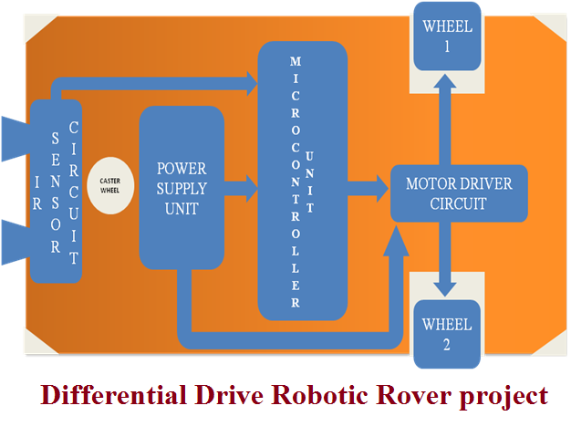
Differential Drive Robotic Rover project

The main aim of this Differential Drive Robotic Rover project is to whenever obstacle finds the robot then takes the diversion from that position. The obstacle can be founded by using sensors, here the robot consist of two motors, each and every motor control the operation of the vehicle moving forward, backward, left and right this can controlled by the  remote. IR rays are used for the detecting the vehicle, there are two main parts are working with the IR those are emitter, detector in this emitter emit the infrared rays and detector detect if any obstacle is present in that motion of moving, this type of robot mainly used in the industries. Here in this project use the microcontroller because the sensor send a signal to the microcontroller then it controls the operation, here separate sources are required for the motor and the microcontroller.

The robot consist of power supply unit, battery charger unit, IR sensor circuit, microcontroller unit, motor driver, and DC motor, power supply required for the microcontroller and motor is different, 5Volts for the microcontroller, 12volts for the motor driver circuit, design of IR sensor circuit, the microcontroller used here are AT89C51, 256kb of RAM, interrupt handling, interrupt recovery time and this robot is most reliable and cheap around 2000/-only.

Differential Drive Robotic Rover project

This project architecture works with IR Sensor circuits and these are directly connected to the micro controllers with motor driver circuits as well as power circuits and different wheels.

Download Differential Drive Robotic Rover full project document and report, Paper presentation, seminar topic.

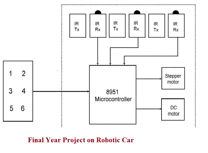
Final Year Project on Robotic Car

The main objective of developing this Robotic car is to provide automatic method for controlling of microcontroller based electronic robotic vehicle. Here we have used Keyboard based operations to move the positions and speed of the car, keyboard prepared in this application is looking like computer keyboard and has the functionalities like left key used for turn left the car wheels and position, right key used for turn right the car position, enter button used to stop and start the car. Simple motors and stepper motors, micro controllers, transmitters, receivers, LCD displays, LED equipments used to impalement total robotic movement system. 8951 Microcontroller connected to the keyboard and operations can be done by car operators in the vehicle control room. IR transmitter and receiver sections, Stepper motor, DC motors directly connected to micro controller in the circuit diagrams.

final-year-project-on-robotic-car

Download Final Year Project on Robotic Car and total Project Documentation, paper Presentation, Seminar Topic.

DTMF Based Device Controlling System Project Report

The main aim of this DTMF Based Device Controlling System project is to controlling the house holding electrical devices like fan, electrical bulb etc. From any where we can control these devices by using mobile phones. This project most useful for reducing the wastage of power; it is also useful for industrial applications. In this Engineering project we are using DTMF (Dual Tone Multi Frequency) Technology, by using this technology we can control the electrical and electronic devices.

             In this project we are using two mobile phones, micro controller, decoder, relays. One of the mobile placed at where we have controlled electrical devices (home), user can be used other mobile. The main function of this project is when user sends commands from his mobile to other mobile placed at home, after receiving commands and it transfer to DTMF signal decoder, which converts signal information into binary codes. This code sends to relays through micro controller, micro controller enable or disable the particular electrical device connects to relay.  Here the microcontroller used in this project is AT89C51, relays are used for the breaking the supply, decoder used of type 8870 chip.

Nowadays this project is most useful because of busy of human activities; it can save power and eliminates manual operation.

Vehicle Information Communication Safety Combined With Mobile RFID System Project

The main aim of this Vehicle Information Communication Safety Combined with Mobile RFID System project is to get vehicle information using Radio frequency identification tag. This ECE project mainly use the equipments of microcontroller of type LPC2148, it is a 64-pin device, RF ID reader is used to drive the vehicle, when the tag is shown to the vehicles microcontroller then access the tag and the information regarding which person is using the vehicle is directly send to the owner by using the GSM technology. In this GSM technology GSM modem is used this modem contains the SIM and the RF ID tag contains the memory, tag consists battery because tag has to send the microwaves to the microcontroller to access. So we need a battery in the tag, there are several types of the batteries, one is chargeable and other is rechargeable batteries and also here using the regulator, filters, rectifier.

The software used in this project are KEIL IDE, embedded C Programming Language, the tag internally it has some memory where one identification is present then that information is sent to the owner by using GSM modem. This project mainly used when the owners having more vehicles so to access the data regarding vehicles which rout the vehicle is going and drivers information, and in this project we can use the accident switches in the front and back side. These switches are connected to the microcontroller. Whenever accident occurs the switches are pressed and the GSM modem send the information to the owner but this project not give the information regarding the vehicle position.

Download Vehicle Information Communication Safety Combined With Mobile RFID System Project Abstract, Block Diagram, Full report and documentation.

3-Phase Irrigation Water Pump Controller for Illiterates Using GSM Modem Project

The main aim of this 3-phase irrigation water pump controller for illiterates using GSM modem project is to control the three phase water pump by using GSM modem for illiterates. In this ECE project the mainly used components are two microcontrollers one microcontroller in control switch another at water pump, one microcontroller send the data then another side have to perform the corresponding functionality, here two G.S.M modems are used in this project, to communicate the both pump side and switch side throw G.S.M the data is send to the other microcontroller. Between the water pump and microcontroller there is interfacing circuit for the interfacing, here two power supplies are needed to perform the operation of water pump, here use the LED indicators to display the information.

The microcontroller used here operates at 5volts, this project equipment is more sensitive because here microcontrollers used, and illiterates can easily know the status of the motor by using LED indicator. The features of this project are easily interfaced, high voltage water pumps are easily controlled, more sensitive, the response is generated from the LED indicator, and wireless connection. To design this project designer should aware of embedded c programming, PCB connections, remote control. This project mainly used in houses. 

Download 3-phase irrigation water pump controller for illiterates using GSM modem Project.

ECE Project Report on Home Automation Using Mobile Communication

The main aim of this project is to controlling the home appliances by using mobile. By using this project we can control tap, lights, fans these can be controlled by using HOME AUTOMATION USING MOBILE COMMUNICATION project. This ECE project is more useful in nowadays. This ECE project mainly uses the equipments of microcontroller (AT89C51), DTMF decoder, speech circuit, relay driver. This project is mainly work using mobile communication. Whenever we press a button in the mobile then the corresponding button is pressed in the controlling section (home). Based on the tone here by speech circuit the corresponding controlling operation is worked.

Here microcontroller used of type AT89C51 this is the main part in this project; it is a high performance 8-bit microcontroller of 4kb size. In the customer mobile each button represents one operation and to test this circuit we need the CRO (cathode ray oscilloscope), before checking the output we have to observe the connections is it correct or not, and the circuit current can be measured by using millimetre. Before soldering clean up all the equipments, check whether the leads of the wires are tinned or not, the leads should be tin, the tinning is done using the LED wire, and it should not be over heated. This ECE project mainly used in gardens to switch off the lamps, in homes to switch off the tube lights, to close the tap, and this project may also used for the security purpose, it have the future of recording and capturing.

Download Home Automation Using Mobile Communication Full Project report, Documentation, Abstract and Circuit Diagrams.

GPS enabled PC based geographic information system (GIS) and routing scheduling system Project

The main aim of this project is to get the vehicle position using the global position system concept. In the past GSM is implemented, do that we can get the vehicle information, which person using the vehicle this information directly send to the mobile of the owner. So that owners easily get the information, but the owner not gets any information of the vehicle location, to find that GPS is implemented. In this project we can find the exact vehicle position. In this ECE project the components used are microcontroller (8051), 8051 micro controller is the 40 pin device, GPS module-to find track the vehicle, and pc-to control the equipments. Nowadays GPS is implemented in almost all countries. Because if our vehicle or mobile are dropped are any one taken illegally then we can easily track using the GPS project. This tracking can be done using the satellite also. United States now using satellite technology to track the position of the vehicle. This process is called as the global navigation satellite system. First earth orbit satellite transmits the microwave signal then satellite receiver collects the data of the corresponding object.

Download GPS enabled PC based geographic information system (GIS) and routing scheduling system Project Abstract.

Project Abstract on Car Parking System

The main aim of this project is to reduce the traffic in the parking place. Normally we can see in the multiplexes, cinema halls, large industries, and function halls there is problem they have to go and search which line is empty and which line having place to park the vehicle, for parking then they need workers for parking in correct position it is the money consumed process. So to avoid this problem Car Parking System project is implemented.

 In this Electronics and communications project we have to use the equipments of microcontroller, Infrared transmitters and infrared receivers for each and every parking slot, IR receivers should be connect to the microcontroller. Here we are using infrared communication because it can support LOS (line of sight communication), and while enter into gate for parking there is the display to get the information regarding which line is empty. This information gives the microcontroller. The microcontroller first give the information to the IR transmitter then it gives to the IR receiver then this information show on the display, so by this process the parking is easy process. So the traffic can be reduced in the parking place of the theatres, multiplex, and in large industries and in commercial places.

Axial Force Sensor for a Semi-Autonomous Snake Robot Final Year Project Abstract

This Electronics and Telecommunication project mainly explained about how the semi autonomous snake robot uses the Axial Force sensor. By using this technology we can control the difficulty places in industry. And the snake robot mainly uses the sensors. There use the four sensors in four sides and also use the microcontroller for the purpose of   controlling the robot. In this technology we used sensors whenever the temperature increases in the industry then automatically sensor give the signal to the microcontroller the microcontroller then automatically active the robot and we can avoid the problems in industry. Normally the robots cannot access the data easily but by using the mobile robots in that we used the sensors and microcontroller these are worked with wireless communication. The mobile robot use the 3D technology to find the location, in 3D it uses 3D sensor.

Snake Robot Features and Advantages:

                         Snake robot is the robot and it consist of many joints and these snake robots are free to move anywhere .this robots can roll, extension and pitch. Firstly implemented the joints close to each other all this become universal joint. This technique is not suitable for all projects; next technology is the joints are made based on angles. This technique is called DOF. Here first take a sphere and next cutting in to half then the two directions can be found, if we rotate that sphere then another two directions also covered. This DOF technique is implemented in the snake robots. this project mainly used in industries.