Intelligent Train ECE Project Report

Introduction to Intelligent Train ECE Project:

In India largest means of transportation is through railways. We have a very sophisticated and well established railway system. India’s railway network is the biggest railway network in the south Asia. There are different types of trains according to the speed and stops of the trains.

A single train can transport much number of people and goods. Even though our railway system is well defined and designed the train accidents are more frequently happening. In these train accidents we are loosing many lifes. If we can add intelligence for the trains then we may avoid most of the train accidents.

We can develop efficient methods like train signal control system using micro controller which works on signals.

In this project we can add intelligence to the train with the help of microcontroller, coordinating it with the DC motor of the train which controls the speed of the train. In this project we use GPS module to locate the train which is given as input to the PIC.

Microcontroller forms the heart of this project as it only controls all the functions. Latitude and longitude of the location given by the GPS module is  compared with data already present in the microcontroller, this helps LCD to display and announce the station names.

The main device in this project is track break detector which detects whether the track is broken or not. If the track break detector found any breaks on the track then train will stop immediately at any point and the door will be opened.

By this way using automated intelligent train we can avoid maximum number of train accidents occurring due to track breaks and can save many life’s. 

This application is a fully automated and robust system which has the advantages of less time delay, quick response and low power requirements gives a safe journey to you all.

B.Tech ECE Project Idea and Report on Intelligent Traffic Control using PLC

Introduction to Project Idea and Report on Intelligent Traffic Control using PLC :

These days along with the increasing demand in utilization of automobiles across the globe it’s became a heavy burden upon traffic control authorities in order to control the abnormal traffic occurring on roads. Human technology invented oa tool to control the traffic by introducing traffic signals controlled by well designed technique called programmable logic controller (PLC).

Automation technologies are gaining reputation in this era, the human efforts are reducing in the road traffic control systems. These artificial intelligent systems undergoing serious research in order to provide the better solutions.

Our project gives a unique solution for the over traffic occurring in these days. In this we use Programmable Logic Controller (PLC). PLC is the most suitable controller for the current traffic problems. Before the invention of PLC the controlling operations in automobiles are done by using timers, counters and relays.

The total circuit became complex in those days now due to invention of programmable logic controller which is nothing but an digital computer make an easy path way for these operations. Our PLC technology is very beneficial when compared to others like relays, timers etc. It is a highly reliable, easily maintained with minimum risk content, less complexity with small size, the initial cost and maintained at a very low cost, programming and reprogramming the plant can be performed.

The basic operation principle of the traffic controller is fed to the controller by means of program under certain conditions. The soft ware used here is LOGO! Soft Comfort V5.0 it’s a user friendly interface uses either a ladder method or functional block method. Its works based on the conditions given i.e.; individual censors are placed at individual lanes operated at different time intervals depends upon the number of vehicles present in that particular lane. The basic working elements and conditions are programmed which are elaborated in this paper.

Download  B.Tech ECE Project Idea and Report on Intelligent Traffic Control using PLC .

ECE Project Topic on Load Monitoring and Breaker with Digital Display Using Microcontroller

Introduction to ECE Project Topic on Load Monitoring and Breaker with Digital Display Using Microcontroller:

In this paper Load monitoring and breaker with digital display using microcontroller we discuss mainly the method to solve the problems caused due the flow of over currents in electrical equipment. The main aim of our project is controlling and coordinating the flow of over currents, inrush currents to safer limit. The system consist of load current sensing circuit, comprises of two major components current transformer ,A/D converter, half wave rectifier and filter.

The current transformer is basically step up transformer the secondary side output of the CT always varies in accordance with the load current from its primary side and then this variable analog voltage is converted into digital pulses. And passes it to micro controller and this signal gets amplified using a half wave rectifier and filter.  The Micro-controller unit used in our project is based on ATMEL 89C51 Micro-controller chip design. The ATMEL AT89C51 has low power with higher performance CMOS 8-bit microcomputer with 4K bytes of flash programmable and erasable read only memory (PEROM).

The chip technology used here is CMOS (complementary metal oxide semiconductor) logic technology is the combination of both NMOS and PMOS will provide us high flexibility with minimum investment and multiple computing. The required operation conditions are programmed in micro controller chip. The output of the micro controller is connected to the digital display where we note the readings.

The current transformer is designed to deliver power a of 1 Amp,230V AC at the secondary side, and the expected  Primary is designed to operate at 13V AC and it takes nearly 22Amps continuously when the current transformer is fully loaded. Our project work “Load monitor and Breaker with Digital Display using Micro-controller” is well designed, tested, undergone practical verification. This paper addressed a new way monitor the conditions under overload conditions, they can be periodically update the conditions by storing the previous data. in future by increasing the diameter of the primary  coil of the current transformer we can improve current ratings.

Download  ECE Project Topic on Load Monitoring and Breaker with Digital Display Using Microcontroller.

8085 Microprocessor Seminar Report for ECE Students

Introduction to 8085 Microprocessor Seminar Topic:

They are the microprocessor developed by Intel Corporation. 8085 is the 8 bit microprocessor that used +5V DC supply for its working. They are very old processor used around 1975s. it comprises of three parts. Every part has beeb assigned its work. First is arithmetic and logic unit, it performs all the calculations like addition, subtraction, AND operation, OR operations etc. Second is control unit, it sets the instruction timing, it control the timing of input and output operations, means it controls the entire operations of the microprocessor. Third is registers, they are used to store the information for temporary time. 

8085 have various registers sets that have their own functions. There is special register called accumulator. All results are first stored in the accumulator then it can be moved to other registers like B, D, H, E, and L. They are the general purpose registers.

There is flag register that is used to set the sign according to the operation like Zero, carry, auxiliary, Sign and parity. Another register is program counter that maintains the sequence of operations. Last register is stack pointer that is used to store the instruction in the memory.

8085 have 40 pins and all have their own working. 8085 have different buses that are used to carry information and data. Address bus is used to carry the respective address of the data.

They are unidirectional. Address/data bus is used to carry address and data both. They are bidirectional in nature. If the signal is high then it will act as data bus otherwise act as an address bus. Control bus is used for controlling the operation of the microprocessors. They are not completely unidirectional and not completely bi-directional. They work on 10 control lines.

Download  8085 Microprocessor Seminar Report for ECE Students .

Mini Project Report on Dtmf Based Mobile Phone Controlled Robot

Introduction to Mini Project on Dtmf Based Mobile Phone Controlled Robot:

We use embedded systems in our daily, we are dependent on them. They provide us digital information’s. Almost all the processors that are developed are based on the embedded systems. They are multipurpose systems designed for the systems like computers, electronic devices.

Every embedded system is based on the microprocessor. It has ROM is used to store the software of the microprocessor. Or we can say that embedded system is a system in which we directly process our code in to the hardware and the software used is just for support and to provide flexibility.

An embedded system contains many memory chips which are used to load the software. In these systems contains three parts hardware, operating systems and application software example PC. 

They are used in the control systems. Also used in the robotics, embedded PCs, signal processing, network equipment’s etc. there are four types of embedded systems used like stand alone for microwaves, digital cameras etc., real time for missiles or DVD players etc. , network based for webcam etc. and mobile devices.

Microcontroller:it is a device that is implemented in the microprocessor that is used to control the functions of the processors. They don’t calculate results but they control the different part of the microprocessors. It also provides delay to some parts for proper functioning of the systems.

They have series of registers that are used to store information and interrupts that are used to provide delays.

They also have data memory like ROM and RAM. They have special type registers like timer registers, dual data registers and interrupt registers. They use only +5v of the power supply for their working. They are used for controlling and monitoring the systems. They use less power and give high performance.

Download  Mini Project Report on Dtmf Based Mobile Phone Controlled Robot.

RFID Based Project on Embedded Palm Device for Guiding Applications Using ARM-7 and RFID Techniques

Introduction to RFID Based Project on Embedded Palm Device for Guiding Applications Using ARM-7 and RFID Techniques:

The main objective of this paper is to develop a embedded palm device. In our modern life ,we expect the devices which are intelligent and can satisfy our needs. We need the devices which makes our work simple and faster. When the visitor visited the museum previously the information about the exhibit is given through conventional audio cassette system, in this system there are many problems  and this focused them to develop a guide system for museum  by using personal digital assistants (PDAs) .

This can automatically retrieve all the information about the exhibit which the visitor is looking at. Hence user doesn’t require to search for the information about the exhibit every time.

Brief into design and working of Embedded Palm device:

This embedded palm devices consists of LCD, Arm processor, RFID Reader, Keypad, Flash Memory and audio amplifier circuit. RFID readers use radio frequencies for transmitting data attached to a tag. These are used for automatic identification and tracking purposes. Keypad helps the user to communicate with the device.

Flash memory is used to store the information about the exhibit. Here also the heart of the project is arm processor. The arm-7 processor is used. These processors makes use of von-neuman architecture and is specially designed for devices which use low power. Digital to analog converter is prebuilt in it. Audio amplifier circuit is used to play the files which are stored in flash memory through processor. LCD displays the information about the exhibit. 

Download  RFID Based Project on Embedded Palm Device for Guiding Applications Using ARM-7 and RFID Techniques .

CAN IP Core – Digital Design and Realisation

Abstract

In today’s world, the communication in a system is computerised in order to reduce the Manufacturing cost and for more reliability. The CAN protocol is the standard for high speed, mission critical, real time control networks in many networks. The CAN protocol is reliable, cheap and last a long time. This project explains the way of designing a CAN module, using the top-down methodology for creation of synthesisable HDL (VHDL) description of the protocol functionality. The project design is simulated and synthesized to get a gate-level net list.

CAN characteristics 

  • Multiple masters
  • Priority –based transmissions: on message ID by node hardware
  • All messages are received by all nodes; ID is the priority
  • Message filtering: nodes filter messages using Ids before use
  • 11-or 29 bit message ID
  • Fixes message forms: variable length, to 8 bytes of data
  • Built in error detection and recovery
  • Guaranteed latency for high priority messages
  • High reliability: CRC, message frame check, transmission monitoring
  • Bit transmissions to 1Mbps
  • Accommodates 100m between nodes (40m at 1Mbps) (M360 CANbus M-module)

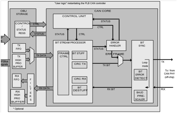
Block Diagram of CAN IP Core

 Block Diagram of CAN IP Core

Microcontroller Project on Wireless Technology Based Consumer Application Display System

Introduction to Microcontroller Project on Wireless Technology Based Consumer Application Display System:

Our Project is aimed to come out with an idea of “Data Receiving” with no loss, by implementing of current Wireless technology. The wireless technology we are relied on is ZIGBEE Sensor Network which is explored for accurate and real data receiving. 

The Current System   

The current technology of advertising display system is based on opto-electronic devices, in which the motion digital video is projected on to the screen from a somehow closed or fully covered conveyance or transportation.

The theory of this project here is to eliminate reasons in improper display of the motion video at transportation area. The modular features of invention for easy seeing and nearer of a force display system in the transit area consists of parallel wire mechanism and high speed motion makes the view high standard. 

We have come up with the topic of how to regulate issue of the force display system run by parallel wire mechanism. We have done enough research on developing the quality or performance of display systems by proposing Control laws. The systems performance experimentally  be proved in terms of  quantity, stated that Proposed control laws supports the more acceleration and less reaction force compare to any force display systems. 

The current system is normally based on an Electronic display system, more commonly to the Database Driven Electronic Display System. The Multilanguage Self- Contained Unmanaged Database- Driven Real Time Digital Advertising Display System has dramatically changed the advertising style of Products of the Retail sector with an idea of aiming audiences directly through Display systems in transit areas. This creates to promote the products easily and in a very efficient manner with in limit finance and time. 

The Retail Sector had been using the corporate databases such as Oracle, Microsoft SQL for their promotion of products in the Stores and outside by hoardings. The Multilanguage Self- Contained Unmanaged Database- Driven Real Time Digital Advertising Display System uses high speed internet for their communications and advertisements with upgraded information of the product displayed online. 

Proposed System 

Our innovation is based on the “Wireless Technology based consumer application display system” to reduce the difficulties of Consumer application display and complicated system. Our project is consisting of three units. First is Application User Unit, second is User Display Device 1 and third is User Display Device 2

The Application User Unit is containing ZIGBEE, a Receiver or Transmitter, and PC a server. 

The User Display device 1 and User Display device 2 are the modules that work like a receiver units with user friendly ZIGBEE modules consisting of Microcontrollers that collects data from modem and passes it on LCD display. 

Software specifications include Keil version 3 and Flash magic. Hardware specifications include ZIGBEE module, microcontroller, LCD display, and keyboard.

  Download  Microcontroller Project on Wireless Technology Based Consumer Application Display System.

Micro Controller Based IVRS Based Result Announcement Project Report

Introduction to IVRS Based Result Announcement Project:

Process Control comes under Statistical and Engineering field which is tackling architectures, mechanisms and algorithms to regulate the result of particular process. Industrial Processes is dependent on chemical and mechanical procedures used to be a part of manufacturing of any products on huge scale. Industrial Processes in the heavy industries needs controlling system to observe any industrial processes that is going to be completed with in a time, great accuracy and precision. 

Industrial revolution started with human effort with minimum requirements of machines which soon became needed to produce more products as demanded. The mechanization came into industries with minimum human effort to produce and machine was doing a work of human where as human was operating machines. The industrial automation now has much reduced the work of man by automatically controlling the machines and its processes. Automation provides an industry to produce huge scale of products with great accuracy and less effort. 

The commodity became now cheaper and widely available because of automation. The wastage of Raw material has been reduced and hazardous materials as by products can be measured. 

The productivity of an industry can be increased by combining machines with electronics with regulating high speed, accurate movements, analog measurements and user friendly machines operation display or interface. The wireless technology does this by operating things efficiently. 

The Proposed project is based on the Microcontrollers that operate process control systems. The microcontroller operates the industrial parameters. Apart from Microcontroller the other things are DTMF, Mobile phone, Voice processing unit and lastly power supply. The Software used for the project are Keil Software for C Programming, Express PCB for layout design, Express SCH for schematic design.

The application software is developed in µVision 3. 

The project is highly designed and passed the quality testing. The IVRS makes human effort to remotely operate industries by automated systems.

  Download  Micro Controller Based IVRS Based Result Announcement Project Report.

Microcontroller Project Report on Aeronautical Crash Prevention System through RF Communication

Introduction Micro controller Project Report on Aeronautical Crash Prevention System through RF Communication:

The main objective of this paper is to prevent collision of aircrafts. Here communication is done through RF. RF is preferred due to its features like high Bluetooth range and can detect long distance objects and which are travelling at all sides of the main object. This system consists of microcontroller, LCD, buzzer, transmitter/ receiver, Encoder/Decoder, power supply.

Brief into design and working :

In this system the design involves two sections namely transmitter and receiver section. In the transmitter section, microcontroller generates the parallel data and is encoded, and then the parallel data becomes serial data after encoding and is transmitted through RF transmitter. In receiver section, the receiver receives the transmitted serial data and decodes the serial data into parallel data by using the decoder and is given to microcontroller.

The microcontroller takes the action and status is displayed in the lcd and the buzzer starts initially. Coming to working of this system, each and every aero plane consists of both transmitter and receiver. Every aero plane has an specific IP address. The transmitter keep on transmitting the ip address and if any aero plane is found near by then the receiver receives the ip address of aero plane nearby.

If the receiver receives the information about other aero plane that means it is within the range of hundred meters. Then the status is displayed in the LCD and the buzzer starts .So, when the buzzer starts and status is displayed we can divert the planes without colliding.

Download Micro controller Project Report on Aeronautical Crash Prevention System through RF Communication .