GPS Navigation Robot Final Year Mechanical Project

Positioning Sensors Used To Navigate On Rough Terrain:

Global Positioning Sensor:

Constructional Working of GPS:

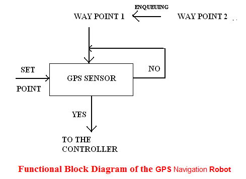
GPS sensor for Navigation Robot is used to navigate the bot reach the fixed destination. Here we use differential gps system, where the carrier frequency is very high even at low signal status certain adaptive methodologies to reach our destination. The functional block shows how the operation is performed by our bot. 

Functional Block Diagram of the GPS Navigation Robot:

 Functional Block Diagram of the GPS Navigation Robot

The block diagram of Final Year Mechanical Project clearly shows the functional working of gps that is here the set point (current position) is compared the first waypoint. Once the destination is reached the program memory enqueue the second way point and so on. If the designated waypoint is not reached again it checks till the destination is reached. 

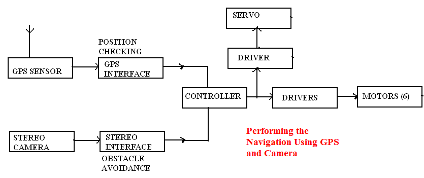
Performing the Navigation Using GPS and Camera:

The effective way of using adaptive robotic technology is performing the complex operation simultaneously to do the desired operation. Similarly we have performed the simultaneous operation by performing both obstacle avoidance and positioning using stereo camera and gps sensor respectively. The main advantage of performing this GPS Navigation Robot operation is maximum nearness error can be avoided that is created during real time positioning. The block diagram clearly shows how the navigation is performed.

 Performing the Navigation Using GPS and Camera

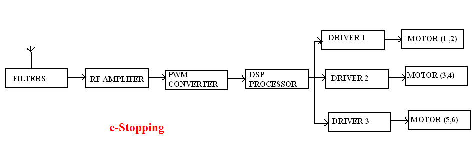
e-Stopping:

we perform the e-stop operation by providing stop signal to the driver .this we attain by converting the availabe frequency (crystal frequency) to PWM signal by using PWM converter .this signal is fed to the motor driver to stop the bot it is be. The block diagam shows the operaton of e-stopping.

e-Stopping

Robotic Project Report and Documentation

The following algorithm for robotic project report & documentation describes the sequence of operation for both lane detection and obstacle avoidance using Image Processing Analysis.

For Lane Detection:

STEP 1: Initialize the camera.

STEP 2: Take the different orientation of the given lane and pre-process the image and store it in the SRAM.

STEP 3: Now allow the camera to traverse the lane.

STEP 4: Take the snap of the lane and check with the data base.

STEP 5: Perform the controller action.

STEP 6: Repeat the process till the destination is reached.

For Obstacle Avoidance:

STEP 1: Initialize the camera.

STEP 2: Observe the environment.

STEP 3: Store that in DRAM.

STEP 4: Do self windowing technique and determine the least pixel rate by using the analysis.

STEP 5: Allow the controller to take the action.

STEP 6: Repeat the process till the destination is reached.

Robotics Final Year Project Ideas and Topics

Constructional Working of Robotics:

Electronic Engineering ECE Approach:

Camera:

In our Robotics Final Year Project we have two cameras

a) C-MOS camera sensor

b) Stereo camera

          The C-MOS sensor camera is placed at the center of the bot and the stereo camera is placed at the center of the bot and the stereo camera is placed at the top of the bot. the camera is tilt to an angle to make the projection perfectly projected to the center of the object.

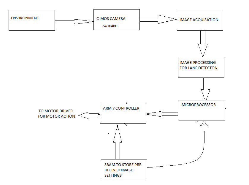
The C-MOS camera is used to perform more specifically for the lane detection. It is used because of its very high sensitivity to light, low power consumption and low cost. The output is digital, so it is directly fed to the controller to take the action. The functional block diagram shows the importance of camera action.

Technical Features of the Robotic Camera:

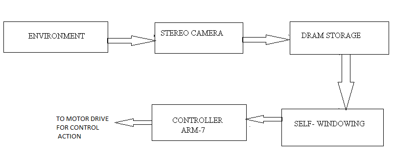
The Image processing and Image acquisition is performed by the on-board micro processor and the result of stereo and C-MOS camera is stored in SRAM (Static Random Access memory) and DRAM (Dynamic Random Access Memory) respectively.

The lane following is pre processing method, so the sample of images are pre loaded to the SRAM and it’s been cross checked by the controller and necessary action is given to the end effector. 

          The Dynamic image processing is carried out by using stereo camera where the self-windowing algorithm is used for real time variation. It is been stored in DRAM and synchronously signal is given to controller to perform the end- effector action.

Block diagram of the robotic project idea clearly show the importance of two cameras.

For lane detection:

For lane detection

Obstacle avoidance:

Obstacle avoidance

 Stereo camera is used for obstacle avoidance performances, since it has very high resolution.

Mechanical Engineering Projects on Robotics

The computational robotic feature was developed using a mechanical system engineering approach with emphasis placed on the understanding the inter-relationship between system components and on maximizing the overall system performance.

The Mechanical Engineering Project development of fully autonomous is a very complex task which holds the consideration of several factors. First, the appropriate view of providing and utilizing autonomy must be determined for each application. For example, the sensors used in this robotic project for image analysis and global positioning is high a time-variants, so this will directly create impact on any set of tasks designed.

Here we tried to manipulate the entire operation carried out by the Robotics Engineering itself that is it has its own capacity to take any decision under any environment without interference.

The integration is very difficult because it requires the assembly of many complex sub systems into a high degree of interconnection and synchronization.

From a Mechanical and Electronic engineering perspective, a well-defined architect provides the underlay framework for achieving reliable maintainable cost-effective system. N Such architecture does this by enabling methods coherently integrating diverse physical, functional and disciplinary sub-systems.

Functional block diagram of our robotic model:

General block representation: 

general

When we analysis these blocks we can acquire the solution for given problem

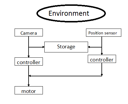
 environment

The general block diagram of Final year mechanical project clearly shows the importance of sequential operation to perform to attain the targets.

The camera which acts the eye for the bot which captures the environment and dynamically analyze the variation and is stored in temporary storage device and its being compared by the processor and action is given to the motor. 

Robotic Projects for Electronics ECE Engineering Students

Have keenly analyzed and designed autonomous robot by using various latest technique and mechanism to reach our destination.

Hereby we have spilt the Robotic Projects for Electronics ECE Engineering Students into mechanical and electronic parts.

The Electronic ECE consideration holds:

  1. The Camera specification ,
  2. Motor action,
  3. Microcontroller and processing unit,
  4. Global positioning system,
  5. Storage unit. 

The Mechanical consideration holds:

  1. The Design of the Robot,
  2. Kinematic design,
  3. Model using designing tool.

The Robotic Project describes the complete prototype of our design and the novel approach followed for construction.

COMPONENTS USED TO DESIGN OUR BOT:

HARDWARE SPECIFICATION: 

Microprocessor    : ARM 9 (VME bus based)

Microcontroller    : ARM 7, MC89C51, MOTOROLA 68HC11

Bus controller      : FireWire Controller (IEEE 1394 interface)

Motor                             : 40kg torque, 150 rpm, Voltage rating 24 V, Current 30 mA.

Camera                 : Stereo camera (obstacle detection)

                               C-MOS sensor (lane detection) 640×480,15FPS

SOFTWARE SPECIFICATION:

Visual C++     (Image Processing)

Embedded C   (Controller)

UNIX operator (Processor)

Robotic Projects for Mechanical Engineering Students

Our Robot Mechanical Project design concentrate on working with real time environmental variation and least power consumption device. The main approach of the bot to a particular situation is based on the micro controller and processors which en-route to perform serious mechanical and electronic operation. We use two standard camera C-MOS camera and Stereo camera to perform lane detection and obstacle avoidance respectively. Controller controls the camera action, GPS sensor, motor drivers and according to varying environment. Lane detection and obstacle avoidance is done by using image processing. The controller performance of Robotic Projects for Mechanical Engineering Students is concentrated mainly to navigate on any surface under any condition. The different driver circuits and interfacing units are used to integrate the mechanical element with electronic components. The control signal is sent to standard bus controller from the various controlling system. The low power consuming sensors and controllers are used to perform the action. Indirectly we are concentrating on minimizing power wastage.

Main aim of the Mechanical System:

The dimensions of the mechanical engineering projects robot are 1600*965*810 mm which is based on the design modeled in pro-e modeling. The kinematic approach to build the bot is based on the chain linkages; we have used Double Rocker Mechanism. With the presence of linkages there is no separate suspension mechanism needed. At all point of times and at all positions always all six wheels will be touching the ground. This is the most advantageous point of having linkages.

The locomotion of bot is designed with six wheels so that the stability of the vehicle is high. All the wheels are given independent drives by each wheel setup having a motor. In addition, four servo motors are placed in the front and back wheels. So the wheels can be turned to steer in any direction. The wheels if properly turned to the required angle, the entire vehicle may completely turn in its position up to 360°. The speed of the vehicle is also controlled by PWM i.e. minimizing the voltage supply given to motors. Hence in overall the bot is designed to move autonomously on all terrains and crossing all obstacles.

Conclusion of this Robotic project Report:

Our mechanical engineering project- pipe inspection robot is extended to identify the history of navigation from the time of start to current running location at various intervals by providing separate internet protocol (IP) based server to note the event history. This could be accessed only by the administrator.

Peristaltic Pumps Mechanical Seminar Topic

Introduction to Peristaltic Pumps Mechanical Seminar Topic:

Peristaltic Pumps are one of the most common items that we find in our house premises; a peristaltic pump is one of the displacement pumps which are positive in nature and is used to pump various kinds of fluids. The name “Peristaltic pump” was derived the word “peristalsis” which is its pumping principle. It consists of a flexible tube, rotor with rollers, shoes or wipers, pump casing etc. The fluid is kept inside the flexible tube or hose which compress and relaxes making the inward and outward flow of the fluid. For that rollers attached with the rotor, shoe and wipers are attached to the external surface of the tube which initiates the compression and relaxation. When the rotor gets started, an under compression tube part closes compelling the liquid to move through. A cam is passed then to make the tube regain its original shape and the fluid flow is induced back to the pump, this process is called restitution.

Advantages of Peristaltic Pumps:

  • Only the interior part is in touch with the fluid and as a result there are less chances of contagion
  • Absence of valves or glands means less maintenance and manufacturing costs
  • No Product slip, linear speed flow makes it ideal for dosing
  • No priming needed, peristaltic pumps are self-primed and seal less with no cavitation
  • Various types of fluids can be pumped
  • Powerful suction and low vacuum force
  • Can handle fluids under high pressure flow

There are many areas where a peristaltic pump can be used; the most common industry which it is used is the water treatment plants where the pumps are used to induce chlorine and other chemicals into running water. Other major industries include paper, ceramic, beverages, detergent, construction etc.  Peristaltic pumps are also used as medical equipment in dialysis machines or bypass machines. Due to its ability to handle high suction pressure it is even used in nuclear plants.

Download Peristaltic Pumps Mechanical Seminar Topic reference documents.

Design of Compact Electro-Mechanical Actuator For Thrust Vectoring Project Report

Introduction to Design of Compact Electro-Mechanical Actuator For Thrust Vectoring Project:

Design of compact electro mechanical actuator for thrust vectoring project is an aero space and mechanical engineering project. Main aim of this project is to design a compact electro mechanical actuator for a trust vector control. Components used in design of this project are belt drive, brushless DC motor and a roller screw. Using these components linear out is achieved from rational input and to these components nozzle and power supply is attached. Precise positioning is achieved by using feedback controllers as pair of resolvers and associated electronics. Design process is implemented in three stages conceptual, preliminary and detailed. Initially entire design is created in 3D model of the EMA which is followed by structural analysis using ABAQUS software.

In present scenario electro mechanical actuators are used in place of hydraulic and pneumatic actuators mainly in case of thrust vector control. Researches are working on alternate technology for hydraulics for control/gimballing of aircrafts. Electro mechanical actuators are best replace for space craft applications.

In this project report we cover detailed explanation on introduction, design principles, problem statement, motor selection, motion profile selection, controller selection, screw selection, screw selection, barring selection and other topics.

This project will help Aeronautical engineering students to gain knowledge on designing EMU and advantages between existing hydraulic system features and new technology features.

Students can find more related project reports and seminar topics on spacecraft from this site for free download.

Download Design of compact electro mechanical actuator for thrust vectoring project report from this link.

Hydraulic lift system for four wheeler

List of Hydraulic lift system for four wheeler:

Hydraulic lift system for four wheeler seminar topic is a mechanical engineering seminar idea which explains about functionality and usage of hydraulic lift systems in lifting vehicles when there is any problem to vehicles. Students can download seminar abstract which consists of detailed explanation about the topic.

Final year b.tech and m.tech final year students can download hydraulic lift system for four wheeler with report from this site for free of cost.

download Hydraulic lift system for four wheeler .


Helicopter vibration reduction techniques

Introduction to Helicopter vibration reduction techniques:

Helicopter vibration reduction techniques mechanical seminar topic idea explains about different procedures need to implement to solve vibration problem in helicopters. This topic will cover details about advantages of helicopter and issues that reduces its performance.

Final  year b.tech,m.tech and diploma mechanical engineering students can download helicopter vibration reduction techniques readymade paper presentation for free of cost. Detailed explanation about this topic is given in ppt.

download Helicopter vibration reduction techniques .