Temperature Monitoring Multi Bedded Hospital

ABSTRACT

This is a PC based temperature monitoring System using Zigbee communication. In this Temperature Monitoring Multi Bedded Hospital project, four temperature sensors in multiplexing mode are connected to the Atmega16 microcontroller which has eight channel in built ADC.

The temperature values of all the sensors are sent serially by the Atmega16 micro controller through Max 232 to the ZigBee trans-receiver module which then transmits this data wirelessly. The control room has another ZigBee module to receive this data which is connected to the communication port of the PC.

A Software “DAQ System” loaded on the PC takes these values and show them on its front panel, and also logs them to the data base “daq.mdb” One can set by the interactive way some parameters like set point i.e. the high limit on the computer screen. High limit and low limits are for alarm. When the temperature goes above high limit the alarm will be turned on.

The Temperature Monitoring application consists of microcontroller Atmega16, the temperature sensor (LM335), Current Driver ULN 2003 and Max232 for the serial interface. The on chip firmware controls reading of the ADC converter, receives commands from PC and sends the reading to PC.

We use the LM335 temperature sensor. The chip produces an output signal that is proportional to the Celsius temperature scale.

SOFTWARE :

• AVR STUDIO
• EMBEDDED C
• UCFLASH

HARDWARE :

• ATMEGA16 Microcontroller
• LM35 Temperature Sensor
• ULN2003 Current Driver
• Buzzer
• Max232 Interface

BLOCK DIAGRAM

IR Based Load Automation Project

IR BASED LOAD AUTOMATION

 This IR Based Load Automation project describes a new economical solution of controlling electrical loads wirelessly using handhelp switchpad. The control system consists of an IR transmitter and receiver, a microcontroller that collects data from the TSOP  receiver and controls the electrical loads ON/OFF operations.

The IR LED acts as a  Transmitter and TSOP1738 Receiver Sensor acts as a receiver The HT12A is IR Encoder and HT12D is Decoder. Momentary switches are interfaced to the IR transmitter through Encoder IC .

The encoder always reads the status of the switches, passes the information to the IR transmitter and the transmitter transmits the information.

At the receiving end, the IR receiver receives this data, gives it to IR decoder. This decoder converts the single bit data into 4-bit data and presents it to the microcontroller. Now, it is the job of the controller to read the data and perform the corresponding actions for load switching.

 Software Tools:

  1. Keil Compiler
  2. Embedded C Code
  3. ucFlash

Hardware Tools:

  1. Microcontroller AT89S52.
  2. IR LED & TSOP1738 SENSOR
  3. Encoder HT12A and HT12D Decoder.
  4. Relays
  5. Switches.

Block Diagram:

 Transmitter Section


Receiver Section

Alcohol Breath Analyser with LCD Interface

The main aim of this Alcohol Breath Analyser with LCD Interface project is to monitor the vehicles for drunk drivers and if the alcohol content is detected, the system should alert the siren.

Alcohol gas sensor will be fixed in the system. The status of the sensor will be continuously monitored by the microcontroller. Whenever the status of the sensor changes, the micro controller detects this and immediately alerts the siren.

The main aim of this Alcohol Breath Analyser with LCD Interface project is to continuously monitor the status of the alcohol gas detector and if its output triggers, the controlling unit activates the buzzer so as to alert the surroundings.

Alcohol gas detector will be interfaced with the microcontroller through a comparator. The comparator is interfaced with the microcontroller. The microcontroller cannot drive the buzzer and cannot provide the current required for the buzzer. Thus, the buzzer will be interfaced to the microcontroller through the transistor. In this case, the transistor acts as a current driver.

Software Tools:

  1. Keil compiler
  2. Embedded C
  3. Orcad.

Hardware Tools:

  1. Microcontroller AT89S52.
  2. Alcohol Gas detector.
  3. Buzzer circuit
  4. LM358 OP-AMP
  5. 16*2 LCD DISPLAY

Block Diagram:

Electronic Eye Embedded System Project

With the increase of robberies, people are acting smarter to cheat the concerned security. To avoid this, we need security system and this can be fulfilled by this project “Electronic Eye”.

This project is based on Intel’s 8051 families of the microcontroller. This Embedded system project is based on highly sensitive PIR Sensor. When you are away for your house and if anyone tries to enter the house by any means the device generates an alarm signal, that is enough to chase the thief, Where the thief will run away so your house is protected. So that you understand that something is wrong at your house, you can immediately call up your neighbor to look after your house.

When you are away for your house and if anyone tries to enter the house by any means the Electronic Eye device generates an alarm signal, that is enough to chase the thief, Where the thief will run away so your house is protected. So that you understand that something is wrong at your house, you can immediately call up your neighbor to look after your house.

Technology & Components Used:

1. Embedded C
2. Keil compiler
3. UC-Flash
4. Microcontroller
5. Power supply

Block diagram:

Schematic diagram


Driver Assistant System Using Ultrasonic Sensor

Nowadays, accidents are becoming a common occurrence on the roads due to negligence or excess speed. If we can avoid, it means we can save many lives. The main objective of our Driver Assistant System project is to develop an anti-collision system for vehicles that can be used for real-time application.

The application is based on ultrasonic sensors to detect the main features of the ultrasonic sensor distance projector and the control circuit power supply.

This Driver Assistant System controls the distance between the car and other vehicles or obstacles to come. 89S52 microcontroller performs all operations. The obstacle distance is displayed on the 16 * 2 LCD screen. If the obstacle is in the sensing zone call ring sounds to give a warning.

Measuring the distance of an object in the way a stationary or mobile person, structure or vehicle is used in many applications such as motion control robots, vehicle control, blind stick, medical applications, etc. Measurement with ultrasonic sensors is one of the cheapest among the various options.

In this measurement application of the distance of an obstacle using a digital ultrasonic transmitter, the receiver module and a microcontroller are. The experimental apparatus and the results are described and explained. The ultrasound view shown here is suitable for measuring the distance between 20mm and 4000mm (4m).

SOFTWARE:

1. Keil COMPILER
2. EMBEDDED C CODE
3. ucFlash

HARDWARE:

1. Microcontroller AT89S52.
2. 16*2 LCD DISPLAY
3. Transistor Driver
4. Buzzer
5. Ultrasonic Digital sensor Module

BLOCK DIAGRAM:

Performance Analysis of Real Time Dynamic Scheduling Algorithms Using Torsche Tool

ABSTRACT: 

Mostly all real time scheduling algorithms are open loop algorithms. So it will not support all the real world problems. While algorithms such as Earliest Deadline Algorithms, Rate Monotonic and the spring scheduling algorithms are supporting comfortable important task set characteristics such as deadlines, precedence constraints, shared resource, jitter etc. Normally real time scheduling algorithms classified into two categories: static and dynamic. Static algorithm requires complete knowledge of task set and constraints whereas dynamic algorithm does not requires complete knowledge of task set. These two open loop algorithms works poorly in unpredictable dynamic systems. Normally all dynamic real world applications have insufficient resources and unpredictable work-load. So closed loop systems are suitable for facing this situation. The performance of CPU utilization is evaluated by using these algorithms into PID controller. Normally PID controller can provide stable control and it does not need any special analytical model. For dynamic system PID controller is suitable one. In this paper I present a feedback control real-time scheduling algorithms and its evaluation corresponding to PID controller with TORSCHE tool box where TORSCHE tool box is especially very much used for scheduling algorithms. TORSCHE (Time Optimisation, Resources, SCHEduling) Scheduling Toolbox for Matlab is a freely (GNU GPL) available toolbox developed at the Czech Technical University in Prague. Performance results demonstrate the effectiveness of the algorithm when execution time varies.

INTRODUCTION:

Based on the real time scheduling categories dynamic scheduling algorithms is suitable for unpredictable environments where as static algorithms need complete idea of the task set. Dynamic scheduling can be again classified into two categories: Resource Sufficient Environment and Resource Insufficient Environment. Resource sufficient environments requires sufficient resources is required for working. Earliest Deadline First(EDF) is an optimal dynamic scheduling algorithm in resource sufficient environments. EDF scheduling is most offer able one in real time scheduling.

All three algorithms must need complete knowledge of the task set what is going to be happening continuously. Those are not suitable for sudden variations in the real time situations. For example robotics, defenses, computational loading applications and other online changes applications. In all pervasive applications the input will receive from the sensors, it will not same predictable values always, it may be different unpredictable values also. For that situation these scheduling algorithms does not suitable.

The timing requirements is the another important problem. Because the timing requirement would be known and fixed. Always the open loop scheduling algorithms work with this fixed set of timing requirements. To solve these problems the only acceptable solution is feedback control real time scheduling.

KEY WORDS:

EDF: Earliest Deadline First, PID Controller: Proportional Integral Differential Controller, CPU: Control Processing Unit, RM: Rate Monotonic.

OVERVIEW:

The following architecture diagram is the basic architecture of feedback control system.
The architecture contains Controller, Actuators, Sensors, and Plant. The Controller which is used to controlled the variable. It has two input and one output. The two inputs are Set point, feedback. The Set point is used to the set the correct value of the controlled variable. The difference between the correct value of the controlled variable and the set point is the error.

Architecture of Feedback Control System:


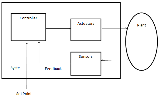
The system is continuously monitor and compares the controlled variable to the set point which is known as the correct value to find the error. Based on the error value the controller calculates the required control value. The actuator is used to change the value of the manipulated variable of the system. Here the Scheduler as the PID controller. Because of the following reasons we choose PID control as the basic feedback control scheduling.

1. In control theory, the scheduling system is dynamic system
2. The PID controller does not need any analytic model.
3. Basic PID control can provide stable control in first and second order systems.

PID Controller:

In my project the PID controller is used to periodically monitors the controlled variable missratio and computes the CPU requested utilization.

The model for Feedback Control Scheduling:

The PID controller is used to help the scheduler as a stable one. It is normally done by
simulations. The Cp,Ci,Cd are the coefficients of PID controllers. The main parameters for the
simulations are 1. The SP is a constant sampling period 2.MissRatio the difference between the
system output and the controlled variable. 3.CPU’(Z) is the estimate CPU utilization. 4. CPU(Z)
is the actual CPU utilization. 5. ug(k) is the ratio of the actual total utilization to the estimation.
6. mrg(k) is the CPU utilization gain. 7. d(k) the disturbance. The estimated CPU utilization is
calculated by
CPU’(z) = ∆CPU’(z)/(z-1)
The actual requested utilization is calculated by
CPU(z) = ug(k)CPU’(z)
The missratio is calculated by
MissRatio(z) = mrg(k)CPU(z)-d(k)
Whereas the transfer function of the PID controller is:
H(z) = Cp + Ci/(z-1) + Cd(z-1)/z
The following diagram is the MATlab simulation model for calculating
missratio. The output is Fed back to the input to improve the CPU utilization and maintain less
missratio values.


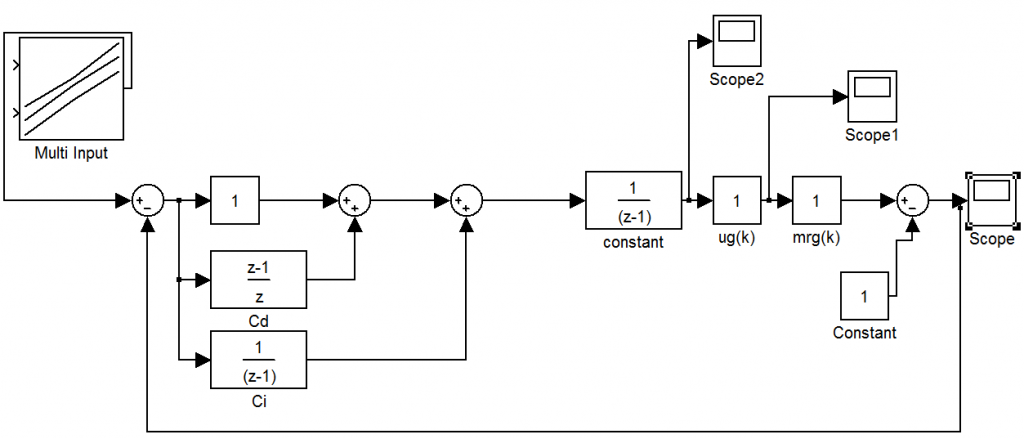
Cp,Cd,Ci has taking as constant one value. ug(k),mrg(k) are both taking as different values and find the different missratio values. Based on this simulation we can justify the following things i.e., the estimated CPU utilization and the actual CPU utilization are approximately equal and there is no domino effect is happened. The coding for scheduling algorithms like EDF,RM are written by the TORSCHE toolbox. Then it is apply in to the controller to improve the CPU utilization. The comparative statement is shown by the graphical format. Compare to the two scheduling algorithms EDF scheduling algorithm could be proved as a good one.

CONCLUSION :

In this paper we are analyzing the closed loop real time scheduling systems. Based on this paper i can improve the CPU utilization and minimizing the missratio values. Because deadline missratio is directly controlled by the scheduler. The performances of two scheduling algorithms are taken and verified using TORSCHE scheduling toolbox. FC-EDF, Least and Latency scheduling algorithms are taken and compared in future. This paper mainly based on “Design and Evaluation of a Feedback Control EDF Scheduling Algorithm by Chenyang Lu, John A. Stankovic”. But I am using TORSCHE scheduling toolbox to shown the performance analysis.

References:

[1] B. Bouyssounouse, J. Sifakis, Embedded Systems Design: The ARTIST Roadmap for Research and Development, Springer, 2005.
[2] J. P. Loyall, “Emerging Trends in Adaptive Middleware and Its Application to Distributed Real-Time Embedded Systems”, Lecture Notes in Computer Science (LNCS), Vol. 2855, pp.20-34, 2003.
[3] K.-E. Årzén and A. Cervin, “Control and Embedded Computing: Survey of Research Directions”, Proc. 16th IFAC World Congress, Prague, Czech Republic, 2005.
[4] Feng Xia, Zhi Wang, and Youxian Sun, “Integrated Computation,Communication and control: Towards Next Revolution in Information Technology”, LNCS, Vol. 3356, pp.117-125, 2004.
[5] J. L. Hellerstein, “Challenges in Control Engineering of Computing Systems”, Proc. IEEE ACC, Massachusetts, July 2004, pp.1970-1979.
[6] Sha, L., T. Abdelzaher, K.-E. Årzén, T. Baker, A. Burns, G. Buttazzo, M. Caccamo, A. Cervin, J. Lehoczky, A. Mok, “Real-time scheduling theory: A historical perspective”, Real-time Systems, Vol.28, pp.101-155, 2004.
[7] C. Lu, J.A. Stankovic, G. Tao, S.H. Son, “Feedback control real-time scheduling: framework, modeling, and algorithms”, Real-time Systems, Vol.23, No.1/2, pp. 85-126, 2002.
[Abde98] T. F. Abdelzaher and Kang G. Shin, “End-host Architecture for QoS-Adaptive Communication” IEEE RTAS, June 1998.
[Becc99] G. Beccari, et. al., “Rate Modulation of Soft Real-Time Tasks in Autonomous Robot Control Systems”, EuroMicro Conference on Real-Time Systems, June 1999.
[Blev76] P. R. Blevins and C. V. Ramamoorthy, “Aspects of a dynamically adaptive operating systems”, IEEE Transactions on Computers, Vol. 25, No. 7, pp. 713-725, July 1976.
[Butt95] G. Buttazzo and J. A. Stankovic, “Adding Robustness in Dynamic Preemptive Scheduling”, Responsive Computer Systems: Steps Toward Fault-Tolerant Real-Time Systems (D. S. Fussell and M. Malek Ed.), Kluwer Academic Publishers, 1995.
[Gerb95] R. Gerber, S. Hong and M. Saksena, “Guaranteeing Real-Time Requirements with Resource-Based Calibration of Periodic Processes”, IEEE Transactions on Software Engineering, Vol. 21, No. 7, July 1995.
[Hari91] J. R. Haritsa, M. Livny and M. J. Carey, “Earliest Deadline Scheduling for Real-Time Database Systems”, IEEE RTSS, 1991.
[Jehu98] J. Jehuda and A. Israeli, “Automated Meta-Control for Adaptable Real-Time Software”, Real-Time Systems J., 14, 1998.
[Leho89] J. P. Lehoczky, L. Sha and Y. Ding, “The Rate Monotonic Scheduling Algorithm – Exact Characterization and Average Case Behavior”, IEEE RTSS, 1989.
[Li98] B. Li, K. Nahrstedt, “A Control Theoretical Model for Quality of Service Adaptations”, in IEEE International Workshop on Quality of Service, May 1998.
[Liu73] C. L. Liu and J. W. Layland, “Scheduling Algorithms for Multiprogramming in a Hard Real-Time Environment”, JACM, Vol. 20, No. 1, pp. 46-61, 1973.
TORSCHE Scheduling Toolbox for Matlab User’s Guide (Release 0.4.0).

Home Energy Monitoring System using SCADA

Existing Work:

In the previous work, the acquired data was using a DSP based device, which is very costly and complex to implement and wired network was used to get current data from a transformer based circuit which in unreliable

Proposed Work:

In the proposed Home Energy Monitoring System work, we are going to execute the concept on a single board computer device, through wireless sensor network. Thus the entire load data i.e. Current, Voltage, Energy consumed will be received on the Master device using a Zigbee Network and a Front end Qt based GUI is designed to view the Data.

BLOCK DIAGRAM

Hardware:

ARM9/11(Friendly ARM, Raspberry pi), 8051, zigbee, current sensor, energy meter, Power supply, Relay, Load.

Software:

OS: Embedded Linux, Language: C/ C++, IDE: Qt Creator.

Applications:

Electric home appliance, Industrial appliance.

Advantages:

Low cost to observer the individual appliances status in the home.

Automatic Switching Of Induction Motor

Automatic Switching Of Induction Motor Abstract:

INTRODUCTION:  Now-a-days, water crisis in India has been reached to alarm proportions and its wastage during transmission is identified as the major cause responsible for the problem. So in order to resolve the issue to some extent we have come up with Automatic switching of induction motor in houses, this project which is a simple model used to conserve water as well as electricity, and can be implemented in the real time work.

BLOCK DIAGRAM:

 Power supply

Over head Tank

Motor pumps the water into the overhead

Tank when switch gets on by microcontroller.

Water level indicating circuit

Sensor

Motor switch

Micro controller (8051)

Motor

Power supply

Water level indicating circuit

Sump or Reserve  Tank

Power supply

Automatic Switching Of Induction MotorEXISTENCE:

The basic idea for the project is water level indicating circuit. The water level indicator is operated with the help of IC 555 timer. The IC 555 timer is provided with inputs as soon as the level of the water in the sump or reserve tank reaches to a predetermined level. As soon as the water touches the predetermined level, the water level indicating circuit indicates its users by alerting through a beep sound.

PROPOSAL:

The above existed idea of water level indicator circuit is used twice to indicate the levels in the sump as well as the overhead tank and the output of the two water level indicators are given as the input signals to microcontroller. The Microcontroller is programmed in such a way that if water level is above the minimum water level in lower tank, water gets pumped to upper tank and as soon as the upper tank gets filled, motor switches off automatically.

TOOLS REQUIRED:

  1. Two water level indicators Software required:
  2. An overhead and underground tank Keil C Software.
  3. 8051 Microcontroller
  4. Power supply

  FEATURES AND ADVANTAGES:

  1. Constant and reliable water supply.
  2. Functions with minimal or no human interface.
    3. Easy maintenance; install and forget for years.
  3. Low cost and it is absolutely affordable by all.
  4. Prevents dry running of motor and so water, energy, power not get wasted.

APPLICATIONS:

  1. Monitoring and controlling of water level in reservoirs, dams are important in applications related to agriculture, flood prevention etc.
  2. Domestic, industrial, medical fields etc.

CONCLUSION:

The main objective of the project is to automate process of water pumping in a tank, ability to detect the level of water in a tank, switch on/off the pump. Hence from our proposal of “Automatic switching of induction motor,” water wastage gets controlled by constant and reliable water supply.

TV Remote Controlled PC and Devices with Password protection

The main aim of this project is to control the computer system using TV remote in a secure way (password enabled). This system also controls the electrical devices connected to the same system. Instead of using mouse, one can use the TV remote from certain distance. This remote can perform all the functions that mouse carries like, Left-click, Right-click and movement of the cursor etc. This facilitates user to open or close any documents, control music system, Google application control etc. User can also use Internet service using on-screen keyboard application which is default with windows.

This system makes use of electromechanical switch called Relay to which the appliance to be controlled is connected. This switch is interfaced to the Microcontroller. The Microcontroller controls this switch according to the input it gets from the IR receiver.

This system consists of an IR receiver that receives the Infrared signals from the TV remote. These signals are fed as input to Microcontroller which processes them and the commands specific to PC operation are sent to the application running inside the computer. The communication between the microcontroller and PC is done by the use of Serial RS232 communication. By using this we can operate any software in computer system like windows media player, browser and etc… To achieve this task, the Microcontroller is programmed with intelligent software written using Embedded C language.

The objectives of the project include: 

  1. Wireless PC control.
  2. Control electrical appliances with TV remote.
  3. Secure way of PC control.
  4. Password enabled control.

This project focuses on the following advancements: 

  1. IR technology.
  2. Mouse control using software.
  3. Conversion of AC supply to DC supply.
  4. Microcontroller and serial port interface.
  5. Embedded C programming.
  6. PCB design.
  7. High voltage devices operation using microcontroller.

The major building blocks of this project are: 

  1. Regulated Power Supply.
  2. IR Receiver.
  3. Micro Controller
  4. Crystal oscillator.
  5. Reset.
  6. MAX 232.
  7. LED Indicators
  8. Electromagnetic Relay with driver. 

Software’s used: 

  1. PIC-C compiler for Embedded C programming.
  2. PIC kit 2 programmer for dumping code into Micro controller.
  3.  Express SCH for Circuit design.
  4. Proteus for hardware simulation.
  5. PC with application 

Regulated Power Supply:

 TV Remote Controlled PC and Devices Regulated Power Supply

Block diagram:


TV Remote Controlled PC and Devices with Block Diagram

Automation of Cars using Embedded Systems Technology

Brief on automation of cars:

In the Automation of Cars system we have a receiver and it receives the signals from the transmitter. We can use microprocessor based design or a microcontroller based design depending on the requirement. We can use a finger scanner for locking the car and a navigator can be placed in the car which gives the location of the car and we can get the direction to the destination by using GPS technology. Continue reading “Automation of Cars using Embedded Systems Technology”