Wireless Live Human Detection Robot Project

A Wireless Live Human Detection Robot Project is autonomous self controlled electro mechanical device witches can perform intelligent actions in real time applications. And these can work with or without the presence of humans and can operate at the places that man cannot even enter.

The only thing is it follows the human activities, in this project human detection robot we use a human sensor for object sensing mechanism. With increasing high speed technologies in robotics had paved a path for new robotic control techniques and evolution of new strategies. Using these we can implement new high performance faster robots control devices.

Human Detection Robot Components Explanation:

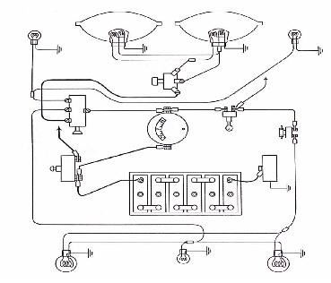
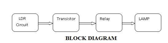
This project consists of infra red sensors used to sense the human bodies and these sensors are controlled by the low power and high performance AT89S52 micro controller, the motor movements are monitored by the micro controller based on the signals from the sensors and the relay signals.

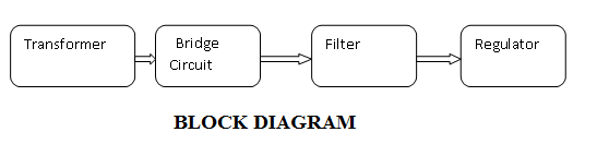
Here we a rectifying unit having a step down transformer, full bridge rectifier, voltage controller for converting 230v ac to 5v dc regulated supply, and an helical gear motor which converts electrical energy into mechanical energy is used for the robot movements, and an electromagnetic relay facilitates the controlling operations  for the micro controller.

Download Wireless Live Human Detection Robot Project Report 

These systems had advanced passive infra red sensors for sensing robot motions, the mechanical design and the working phenomenon is clearly explained in project Report with circuit diagram and block diagram.

Electrodynamics Project on Induction Based Wireless Power Transmission

In Electrodynamics Project on Induction Based Wireless Power Transmission Project we presented a new revolutionary concept of power transfer based on wireless technology, in this we transmit power from one place to other by means of micro waves rather than transmission lines.

Electrodynamics Project

Project Over view:

This is an era of wireless communications revolution we implemented the next generation power transmission system which is also known as micro wave power transmission system or wireless power transmission system, this concept had raised with intent to reduce the losses in transmission and distribution of electricity.

Here in this particular project we transmit energy from one circuit to other by an electromagnetic coupling known as electromagnetic induction. The electromagnetic induction principle states that the change in magnetic field in the primary coil can induce current in the secondary coil, with this method we can transmit or receive energy up to certain distances, Transformer, electrical brush are the examples for the inductive coupling.

The various wireless technologies like inductive coupling and air ionization techniques with comparison of modern laser based power transmission techniques.

Electrodynamics Project System Advantages:

The systems are advantageous because these are comfortable, less risk, shock proof, more environmental friendly, and these are operated at 1 MHz which is a safe limit for humans. But these are transmitted over consisted distances so for far field transfer we implement laser techniques that are discussed in later sections.

As far as applications these systems can be applicable in consumer electronic devices, industrial, robotic applications, direct power transmission for underground systems, power supply for industrial transportation, automatic wireless charging commercial electrical vehicles, security and safety applications.

Download Electrodynamics Project on Induction Based Wireless Power Transmission Project Report

Useful Links:

Electro Dynamic Project Report on Suspension Electro Magnetic Suspension

Wireless Power Transmission PPT

Related Projects:

Load monitor and Breaker with Digital Display using Microcontroller
Remote Controlled Fan Regulator Project Report
Density Based Traffic Light Control System Report
Modern Security Systems with Message Transmitter Project Report
Temperature Control System Project Report

Industrial Robotics Project

Industrial Robotics Project presents an brief idea about the applications of robots in industries, the term robotics is defined as the science and technology which deals with design, construction, operation, and implementation of the robots, and the industrial robots are nothing but the robots which are used for industrial applications, these are the electro mechanical programmable machines that can do works in preventing hazardous conditions.

Industrial Robotics Project

These are highly accurate and consistent, multi functional machines; these devices are interfaced with the computers for monitoring.

Industrial Robotics Abstract:

The main objective of this paper is to place an automated industrial robot in the place of humans in hazardous conditions where man cannot able work. The successful operation of the robots is totally dependent on the programming and the technology used in this programming, so functional programming is an interior function for every robot, recent days robots are controlled by micro computers are highly automated mechanical manipulators.

In industrial automation we control the mechanism of the equipment through a computer based electronic network, but here the robotics involved in programmable automation strategies which had abilities like humans and often termed as anthropomorphic, these robots are programmed to move and performing operations like picking tools and placing them in right position, and doing manual operations so this conditional program is sequentially implemented by the control system within the robot.

List of Content in Project Report:

In this paper we had presented information regarding selection of a robot, elements of robots and their classification, physical configurations, robotic movements, sensors, robotic grippers. A testimonial is presented in this paper and desired controlling parameters were obtained.

Download Industrial Robotics Project Report

Night Light Saver Electronics Mini Project

Abstract:

The Night Light Saver Electronics Mini Project is the best way of economizing the monthly Power (Electricity) invoice. It can also be use for controlling the numbers of appliances avoiding the flip-flopping of numbers of switches regularly, the concept can also be utilized for applications like automatic street light controller, automatic power shutdown in big Industrial area or Campus compound, etc.
The Project is easy to implement and is very cost effective and efficient. It can be implemented by using a LDR (Light Dependent Resistor) or an RTC chip. Using RTC and Micro controller we can keep track of time ( like a clock) and switch the light ON at specified time and switch it OFF at specified interval to save energy., but it again may not coped with the natural phenomenon every time. So the convenient way is to use a LDR.
An LDR is a photo resistor or light dependent resistor or cadmium sulfide (CdS) cell whose resistance decreases with increasing incident light intensity. It can also be referred to as a photo conductor. The LDR output data will reflects the brightness or intensity of light which can be fed to the input of micro controller from where the output load can be controlled accordingly.

Explanation:

 LDR output is connected to the Micro controller and considerations are done in the micro controller to switch the load through the driver section. The Driver section is consist of a small circuit with combination of Relay and Resistor which can also switch 230 Volts operating appliances.

Lighting System of an Automobile Project

Lighting system of a auto mobile project is a simple electronics and and communication project for engineering students. Main objective of this project is to design and understand how lighting system works for cars, 2 wheelers.

Auto light project will give detailed explanation about project design and development with block diagram, circuit diagram, project images. 

Lighting System of an Automobile Project

Objective: 

To design a circuit which will work similar like that of auto mobiles which should full fill all requirements according  to road rules. 

Lighting System of an Automobile Project Introduction:

Every country will have traffic rules and regulations according to that rules vehicles lighting system should be designed. Most of the countries follow same lighting system rules. Lighting system is important for vehicles to drive safely and easily communicate with other vehicles.

This method will reduce accidents so we need to have effective lighting system. This project will give knowledge for students to learn basics of circuit design and auto mobile concepts. 

Components used in this project:

Headlamps

Tail lamps main components

Side or Parking lamps

Stop lamp

Warning lamps

Fog lamps

Panel lamps and Accessories

Interior illumination lamps

Types of switch constituted in the lighting system are:

Light switch

Dip switch

Stop light switch

Lamp Alignment and Focusing: 

For a better view for driver while driving head lamps should be aligned and focused properly. With better alignment illumination will be on right area with our any issues and causing problem to road users. 

These are few rules that to be followed for perfect alignment. 

Front vehicle should be in square with screen

Loding and standing of vehicle should be on level ground. 

Distance should be 25 feet.

Covering one head lamp will be ease for setting. 

Download Lighting System of an Automobile Project Report

Automatic Room Lamp Abstract

Automatic Room Lamp

DESCRIPTION :

First, let us understand why to use Automatic room Lamp? Now-a-days we are going through lots of advertisments of saving electric energy. With the help of Automatic room Lamp we can save and reuse energy. Find the simple block diagram of Automatic room Lamp.

BLOCK DIAGRAM of Lamp

The above block diagram of Automatic room Lamp used to disables the room lamp at day time and enables at night night time. Light Dependant resister(LDR) is the key element of Automatic room Lamp.

Operation:

We need to fix LDR Circuit near to the window/door of home where it can receive maximum sunlight.At day time if we open the door, the resistance of LDR Circuit reduces and leads the transister to remain in cut-off state. So the relay doesnot energize enough,and lamp remains off.
At night time, the resistance of LDR Circuit becomes high and its makes the transistor from cut off state to conducting state. The relay becomes energize and makes lamp to switch on.

We need power supply too operate the following operation.


BLOCK DIAGRAM OF Power Supply

This is block diagram of basic power supply circuit. Transformer is used to step up or step down the input voltage. The bridge circuit is used to convert the alernating current to a pulsating direct current. Since pulsating dc is not desirable, we used filter to convert it to more desirable dc. Regulator is used to maaintain the output of the power supply at a constant level.

Benefits :

Operated only at +5V(d.c)

No use of man power

Used in:

  • Houses
  • Educational Institutions
  • Medical halls
  • Shopping Malls

Logic Gate Emulator ECE Mini Project

Logic Gate Emulator ECE Mini Project mainly developed for Electronics final year students. This Logic Gate Emulator is the device that is used for emulating the microcontroller logic gates like NOT OR, AND etc. this device has different switches that is used to select the device.

They use SPDT switched for the logic gates and these device have two inputs and one output. They LED as the display for the output. Separate LEDs are provided for the separate gates and they glow for the corresponding gate. The whole operation performed by the microcontroller.

Logic Gate Emulator ECE Mini Project Block Diagram:

Logic Gate Emulator ECE Mini Project

8051 Micro Controller Description:

Microcontroller is the single chip based device that contain memory, CPU, RAM and ROM. They also contain clock and they control the input and output signals. They are also called computer chip.Every device and products today work on the microcontroller; they are embedded with millions of products. They are used in the appliances and even in the vehicles. A single car has more than 50 microcontrollers.

AT89S52: they are the 8 bit microcontroller with 8k bytes of the available memory flash memory. They are high performance and low power consuming microcontroller. They are developed using the Atmel technology that create nonvolatile memory and they are compatible with the standards of industries. They uses flash memory, it means that they can be re-programmed.

They are made up of monolithic chips. They are less costly and flexible. They have 256 bytes of RAM and they have 32 inputs and output with timer that is based on the watch dog timer. They have two data timers that have three 16-bit timers, and six vectors interrupt architecture. They have serial port that is full duplex and oscillators and clock circuitry. They are based the static logic for performing operations. They have Idle that stops the CPU but the RAM, timers and counters are still working.

I2C Protocol Implementation with RTC and EEPROM ECE Mini Project

Project Title:

I2C Protocol Implementation with RTC and EEPROM

Introduction:

I2C is the protocol or serial bus that is used in the EEPROM memory to host the interface devices. They are generally used in the embedded devices that have time clocks and they are based on the real time systems. It can be connected with many devices with just two wires. The master devices used initiated the control to I2C and clock is transferred to slave devices. I2C support the speed of 100 Kbits/s. with the help of we can connect up to 256 slave device to the master with just the same two wires.

Project Requirements:

RTC is used in the portable systems for such as smart card reading and logging data that is used to keep the track of the day and time. This coding can be done in the C languages. To install this code on the device we need to have AVR studio simulator and ISP that will convert the C code in the HEX file. We use EEPROM for the memory.

I2C Protocl Implementation Project Block Diagram:

I2C Protocol Implementation block diagram


EEPROM is the nonvolatile memory that is generally used for storing digital data. Once the data is stored it will be permanent and it doesn’t need any power supply to maintain the record. The data entered can erase electrically and then we can add new data. They are simple and small and they easily get fits in to the small chips.

They are used for making real time clock based systems like DS1307ic. We will need ATmega 8535 microcontroller that will manage the whole work on the system, 20×4 LCD panels that will be the display of the system, EEPROM that will be the memory of the device, interface that will be provided by DS1307 hardware module and at last GUI for writing C code.

GSM Based Home Security System Project B.tech ECE Idea

Project Title:

GSM Based Home Security System Project

Introduction to GSM Based Home Security System Project:

When we talk about the security the one thing come in mind that whether our home is secure or not. It is must to secure our home first then look at other things. Our home has always important documents, money and other precious things, that need to be protected from the intruders or thieves.  We also need to protect the home from fire and gas leak as they can also destroy our home.  We can use security device at our home that will warn us from any harm by alarm or sending SMS to cell. We can use 8051 micro controller or 89s52.

GSM Based Home Security System Project Block Diagram:

GSM Based Home Security System Project B.tech ECE Idea

They are low power chips. They are high performance chips with 8 bit and they is flash memory for storing data.This flash memory allows them reprogram when required. Flash are made up of monolithic chips as they are highly flexible and loss cost. They consist of 32 I/O lines, timers, pointers, oscillators, and clocks etc.

For this microprocessor we use the software called Kiel u- version. This provides tools for the development of the software of the 8051. With the help of this we can generate embedded applications. They use the protocol command named as AT command. They receive the message comes from the phone, then decode the SMS, authenticate the number. Then use their ports to control the specific appliances and after the operation send the feedback to the users for the confirmation.AT command sets are used for the GSM service to connect the device with the mobile phones.

Functions: they have internal RAM and ROM.  Input output ports for programming, timers and counters, 8 bit status words. They contain two 16 bit timers with 4 banks of registers. The RAM used has the memory of 128 bytes. 80 bits are assigned for the general purpose of data memory.

Highways Electronic Toll Collection System ECE Project Idea with Report

Electronic Toll Collection is also known as ETC in short and this is an automatism electronic system that helps in collection of toll. This system has been researched by the entire world to be used on bridges, highways and tunnels. Throwing of informations that changes between the labels of electronic that held antennas of RPID and vehicles that usually are fixed at the door frame and roadsides.

The computer that is placed centrally and used to control the others can easily identify the user on the road by the stored information in the appeal of electronic and deducting the pike amount from the advance stored in the account of the bank and the card of the user. There is no advantage in the parking troll collection and thus it can enhance the efficiency of dispose of the ability of traffic on the toll road and the station toll.

This is an automatic toll collection system that has been researched for toll collection purposes. It can be used for collection of the toll amount on the bridges, highways and tunnels. In the parking troll collection there is no benefit. The stall station can be thrown away by the running vehicles at high speed which instead here it has to slow down before the station and pay the charges. With the advancement in the motor transport the use of the traffic highway will also increase.

With the developed areas this trend is quite clear. The demands of the charging management system will not able to meet the semi-manual and manual form of charges. Many vehicles blocked arose at the entrances and the exits as well creating losses in the economy after reaching a specified threshold. The no parking system on the highway helps a lot in solving these problems. This system can be very useful if used properly.